LinMot C1150-PN-XC-0S User manual

August 2019
Documentation of the PROFINET Interface of the following
Drives:
·
C1150-PN-XC-0S/1S
·
C1250-PN-XC-0S/1S
·
C1450-PN-VS-0S/1S
·
E1450-PN-QN-0S/1S
·
E1250-PN-UC
Manual
PROFINET Interface
Doc.: 0185-1090-E_4V9_MA_PROFINET

© 2019 NTI AG
This work is protected by copyright.
Under the copyright laws, this publication may not be reproduced or transmitted in any form, electronic or
mechanical, including photocopying, recording, microfilm, storing in an information retrieval system, not even
for didactical use, or translating, in whole or in part, without the prior written consent of NTI AG.
LinMot® is a registered trademark of NTI AG.
Note
The information in this documentation reflects the stage of development at the time of press and is therefore
without obligation. NTI AG reserves itself the right to make changes at any time and without notice to reflect
further technical advance or product improvement.
NTI AG
LinMot
Bodenaeckerstrasse 2
CH-8957 Spreitenbach
Tel.: +41 56 419 91 91
Fax.: +41 56 419 91 92
Email: off[email protected]
Homepage: www.LinMot.com

Page 3 of 21
NTI AG / LinMot
Table of Contents
1 System overview ..................................................................................................................................... 4
1.1 References .......................................................................................................................................... 4
1.2 Port assignement ................................................................................................................................ 4
2 Setup in a PLC ......................................................................................................................................... 5
2.1 Create a new Project ........................................................................................................................... 5
2.2 Configure PLC Device ......................................................................................................................... 5
2.3 Configure LinMot Drive ........................................................................................................................ 7
3 Process Data Object (PDO) Configuration .......................................................................................... 13
3.1 Bidirectional PDO Modules ............................................................................................................... 13
3.1.1 Default IO mapping with Config .................................................................................................. 13
3.1.1.1 Output Data ........................................................................................................................... 13
3.1.1.2 Input Data .............................................................................................................................. 13
3.1.2 Control/Status ............................................................................................................................. 14
3.1.2.1 Output Data ........................................................................................................................... 14
3.1.2.2 Input Data .............................................................................................................................. 14
3.1.3 Real Time Config ........................................................................................................................ 14
3.1.3.1 Output Data ........................................................................................................................... 14
3.1.3.2 Input Data .............................................................................................................................. 14
3.2 Output PDO Modules ........................................................................................................................ 15
3.2.1 MC Interface ............................................................................................................................... 15
3.2.2 NC Setpoint Values ..................................................................................................................... 15
3.3 Input PDO Modules ........................................................................................................................... 15
3.3.1 Get StateVar ............................................................................................................................... 15
3.3.2 Get Actual Position ...................................................................................................................... 15
3.3.3 Get Demand Position .................................................................................................................. 16
3.3.4 Get WarnWord ............................................................................................................................ 16
3.3.5 Get ErrorCode ............................................................................................................................. 16
3.3.6 Get Current 32b .......................................................................................................................... 16
3.3.7 Mon Channel 1 ............................................................................................................................ 16
3.3.8 Mon Channel 2 ............................................................................................................................ 16
3.3.9 Mon Channel 3 ............................................................................................................................ 16
3.3.10 Mon Channel 4 .......................................................................................................................... 17
3.3.11 Get Current 16b ........................................................................................................................ 17
4 PROFINET Parameters .......................................................................................................................... 18
4.1 Parameters ........................................................................................................................................ 18
4.1.1 ProfiNet\Dis-/Enable .................................................................................................................... 18
4.1.2 ProfiNet\Byte/Word Order\Byte Order ......................................................................................... 18
4.1.3 ProfiNet\Byte/Word Order\Word Order ....................................................................................... 18
4.1.4 ProfiNet\Byte/Word Order\MC CMD Intf Par Order .................................................................... 18
4.1.5 ProfiNet\Monitoring Channels ..................................................................................................... 18
5 Connecting to the PROFINET Network ............................................................................................... 20
5.1 Pin Assignment of the Connectors X17-X18 ..................................................................................... 20
Page 4 of 21 NTI AG / LinMot
1 System overview
PROFINET is the open real-time Ethernet network, in this manual the LinMot profile drives are described.
The LinMot drives act as slave in this network and is implemented with the TPS1 chip from Renesas.
For further information on the PROFINET fieldbus protocols please visit:
http://www.profibus.com/
Programming examples provided by LinMot are listed under: http://www.linmot.com/index.php?id=141
1.1 References
All user manuals are distributed with the LinMot-Talk software the newest versions can be downloaded from
the LinMot homepage in the download section.
Ref
Title
Source
1
User Manual Motion Control SW
www.linmot.com
2
LinMot Drive Configuration over Fieldbus Interfaces SG5
www.linmot.com
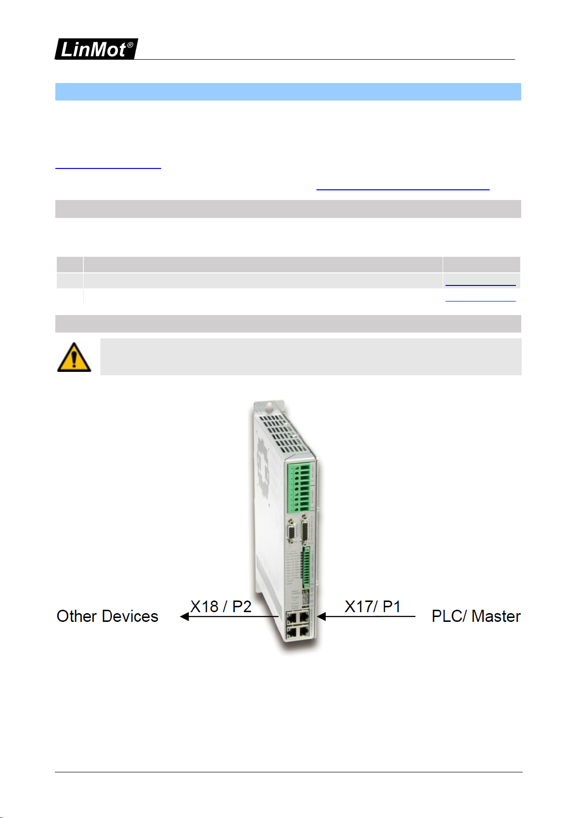
1.2 Port assignement
Attention: Within the PROFINET network normally the topology is defined, for easy setup and
replacement of devices. The real time Ethernet RJ45 connector X17 is the P1 port and the real
time RJ45 connector X18 is the P2 port in this context.
Page 5 of 21
NTI AG / LinMot
2 Setup in a PLC
In the following steps the integration of a LinMot EtherCAT Servo Drive in the PLC is described. In the
example a SIEMENS Simatic S7-1500 PLC and a LinMot C1150-PN-XC drive with a PnP capable motor is
used. It is assumed that PLC and Drive are powered and connected to each other.
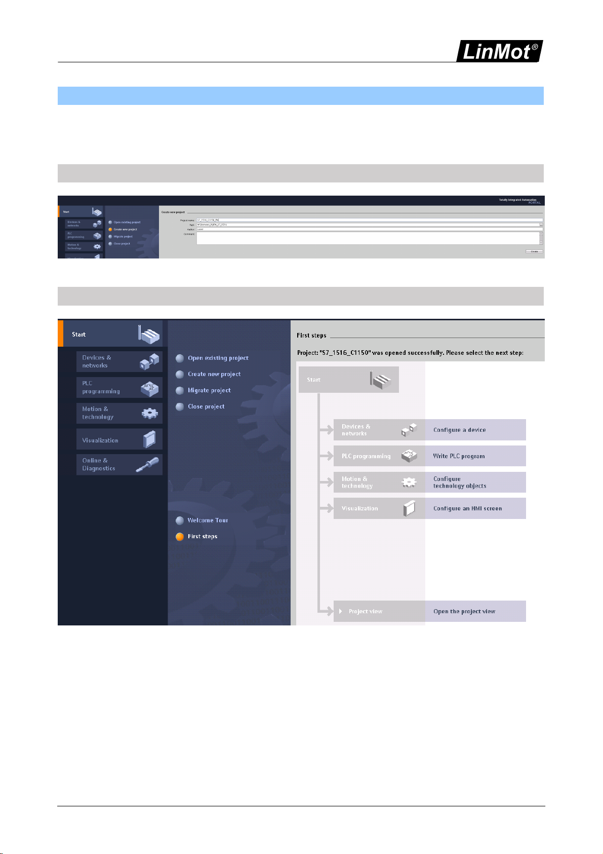
2.1 Create a new Project
create new protject
2.2 Configure PLC Device
Configure used PLC device
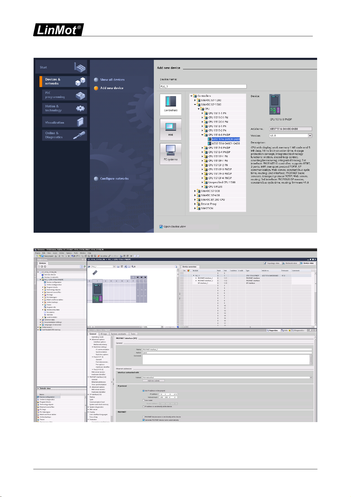
Page 6 of 21 NTI AG / LinMot
Select PLC device.
Configure the PROFINET, set the PLC network address.
Page 7 of 21
NTI AG / LinMot
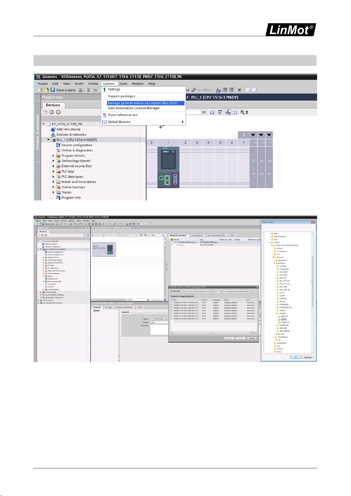
2.3 Configure LinMot Drive
If not installed already install linMot GSD-file.
Select Installation path of the MinMot GSD-files.

Page 8 of 21 NTI AG / LinMot
Select wanted device.

Page 9 of 21
NTI AG / LinMot
In the Hardware catalog select desired device.

Page 10 of 21 NTI AG / LinMot
Drag and drop it frpm the hardware catalog to the network view.
Connect the PROFINET of the drive to the PLC.
In the Topology view define the connection topology

Page 11 of 21
NTI AG / LinMot
Configure the network address of the drive.
By default in slot 1 of the PN-IO communication the “Default IO mapping with Config” is plugged, which is
suitable for most applications.
Compile the Configuration by pressing the button.

Page 12 of 21 NTI AG / LinMot
Download the configuration
After the successful download of the configuration the PROFINET IO communication should be established
and the green realtime bus LED on the drive is on.

Page 13 of 21
NTI AG / LinMot
3 Process Data Object (PDO) Configuration
The cyclic process data is configured in the master and transmitted to the slave during startup. The data
Object modules could be configured by trag and trop to the device slots 1..15.
Overview of the supported Process Data Objects Modules
By default the module ”Default IO mapping with Config” is plugged into Slot 1, with this module most
application should be well supported.
3.1 Bidirectional PDO Modules
3.1.1 Default IO mapping with Config
3.1.1.1 Output Data
Index
Size
[Byte]
Byte
Offset
Name
Data
Type
Tlg 16
32
-
Variables
RECORD
1
2
0
ControlWord
Word16
2
2
2
Motion Command Header
Word16
3,4
4
4
Motion Command parameter 1
Word32
5,6
4
8
Motion Command parameter 2
Word32
7,8
4
12
Motion Command parameter 3
Word32
9,10
4
16
Motion Command parameter 4
Word32
11,12
4
20
Motion Command parameter 5
Word32
13
2
24
Config Header
Word16
14
2
26
Config Index
Word16
15,16
4
28
Config Value
Word32
For the meaning oft he „Control Word“ and the „Motion Command interface“ refer to [1], for the „Real Time
Config Interface“ refer to [2].
3.1.1.2 Input Data
Index
Size
[Byte]
Byte
Offset
Name
Data
Type
Tlg 16
26
-
Variables
RECORD

Page 14 of 21 NTI AG / LinMot
Index
Size
[Byte]
Byte
Offset
Name
Data
Type
1
2
0
StateVar
Word16
2
2
2
StatusWord
Word16
3
2
4
WarnWord
Word16
4,5
4
6
Demand Position
Word32
6,7
4
10
Actual Position
Word32
8,9
4
14
Demand Current
Word32
10
2
18
Config Status Word
Word16
11
2
20
Config Index Response
Word16
12,13
4
22
Config Value Response
Word32
For the meaning of the variables 1-6 refer to [1], for the „Real Time Config Interface“ refer to [2].
3.1.2 Control/Status
3.1.2.1 Output Data
Index
Size
[Byte]
Byte
Offset
Name
Data
Type
Tlg 1
2
-
Variables
RECORD
1
2
0
ControlWord
Word16
3.1.2.2 Input Data
Index
Size
[Byte]
Byte
Offset
Name
Data
Type
Tlg 1
2
-
Variables
RECORD
1
2
0
StatusWord
Word16
3.1.3 Real Time Config
For the meaning of the „Real Time Config Interface“ refer to [2].
3.1.3.1 Output Data
Index
Size
[Byte]
Byte
Offset
Name
Data
Type
Tlg 4
8
-
Variables
RECORD
1
2
0
Config Header
Word16
2
2
2
Config Index
Word16
3,4
4
4
Config Value
Word32
3.1.3.2 Input Data
Index
Size
[Byte]
Byte
Offset
Name
Data
Type
Tlg 4
26
-
Variables
RECORD
1
2
0
Config Status Word
Word16

Page 15 of 21
NTI AG / LinMot
Index
Size
[Byte]
Byte
Offset
Name
Data
Type
2
2
2
Config Index
Word16
3,4
4
4
Config Value Response
Word32
3.2 Output PDO Modules
3.2.1 MC Interface
Index
Size
[Byte]
Byte
Offset
Name
Data
Type
Tlg 3
22
-
Variables
RECORD
2
2
0
Motion Command Header
Word16
3,4
4
2
Motion Command parameter 1
Word32
5,6
4
6
Motion Command parameter 2
Word32
7,8
4
10
Motion Command parameter 3
Word32
9,10
4
14
Motion Command parameter 4
Word32
11,12
4
18
Motion Command parameter 5
Word32
3.2.2 NC Setpoint Values
Index
Size
[Byte]
Byte
Offset
Name
Data
Type
Tlg 15
12
-
Variables
RECORD
1,2
4
0
Position Setpoint
Word32
3,4
4
4
Velocity Setpoint
Word32
5,6
4
8
Acceleration Setpoint
Word32
3.3 Input PDO Modules
3.3.1 Get StateVar
Index
Size
[Byte]
Byte
Offset
Name
Data
Type
Tlg 2
2
-
Variables
RECORD
1
2
0
StateVar
Word16
3.3.2 Get Actual Position
Index
Size
[Byte]
Byte
Offset
Name
Data
Type
Tlg 5
4
-
Variables
RECORD
1
4
0
Actual Position
Int32

Page 16 of 21 NTI AG / LinMot
3.3.3 Get Demand Position
Index
Size
[Byte]
Byte
Offset
Name
Data
Type
Tlg 6
4
-
Variables
RECORD
1
4
0
Demand Position
Int32
3.3.4 Get WarnWord
Index
Size
[Byte]
Byte
Offset
Name
Data
Type
Tlg 7
2
-
Variables
RECORD
1
2
0
WarnWord
Word16
3.3.5 Get ErrorCode
Index
Size
[Byte]
Byte
Offset
Name
Data
Type
Tlg 8
2
-
Variables
RECORD
1
2
0
ErrorWord
Word16
3.3.6 Get Current 32b
Index
Size
[Byte]
Byte
Offset
Name
Data
Type
Tlg 9
4
-
Variables
RECORD
1
4
0
Demand Current
Int32
3.3.7 Mon Channel 1
Index
Size
[Byte]
Byte
Offset
Name
Data
Type
Tlg 10
4
-
Variables
RECORD
1
4
0
Monitoring Channel 1
Word32
3.3.8 Mon Channel 2
Index
Size
[Byte]
Byte
Offset
Name
Data
Type
Tlg 11
4
-
Variables
RECORD
1
4
0
Monitoring Channel 2
Word32
3.3.9 Mon Channel 3
Index
Size
[Byte]
Byte
Offset
Name
Data
Type
Tlg 12
4
-
Variables
RECORD
1
4
0
Monitoring Channel 3
Word32

Page 17 of 21
NTI AG / LinMot
3.3.10 Mon Channel 4
Index
Size
[Byte]
Byte
Offset
Name
Data
Type
Tlg 13
4
-
Variables
RECORD
1
4
0
Monitoring Channel 4
Word32
3.3.11 Get Current 16b
Index
Size
[Byte]
Byte
Offset
Name
Data
Type
Tlg 14
2
-
Variables
RECORD
1
2
0
Demand Current
Int16

Page 18 of 21 NTI AG / LinMot
4 PROFINET Parameters
4.1 Parameters
Attention:
Profinet), which can be configured with the distributed LinMot-Talk software.
With these parameters, the PROFINET behaviour can be configured. The LinMot-Talk software can be
downloaded from http://www.linmot.com under the section download, software & manuals.
4.1.1 ProfiNet\Dis-/Enable
With the Dis-/Enable parameter the LinMot Servo Drive can be run without the Ethernet PROFINET Interface
going online. So in a first step the system can be configured and run without any bus connection.
PROFINET\Dis-/Enable
Disable
Servo Drive runs without PROFINET.
Enable
Servo Drive runs with PROFINET connection.
IMPORTANT: If the PROFINET Interface is disabled, the integrated TPS1-ASIC rests in reset state! No
messages will be sent to other devices connected to the PROFINET-Network via the servo drive.
4.1.2 ProfiNet\Byte/Word Order\Byte Order
Defines the used byte order.
PROFINET\Byte/Word Order\Byte Order
Reversed
Byte order is reversed. For S7 PLCs select reversed.
Not reversed
Byte order is not reversed.
4.1.3 ProfiNet\Byte/Word Order\Word Order
Defines the used word order.
PROFINET\Byte/Word Order\Word Order
Reversed
Word order is reversed.
Not reversed
Word order is not reversed.
4.1.4 ProfiNet\Byte/Word Order\MC CMD Intf Par Order
Defines the used parameter word order.
PROFINET\Byte/Word Order\MC CMD Intf Order
Reversed
Order is reversed. CMD Header - Par word 1 – Par word 0 - Par word 3 - Par word 2 -
etc...
Not reversed
Order is not reversed. CMD Header - Par word 0 - Par word 1 - Par word 2 - Par
word 3 - etc...
4.1.5 ProfiNet\Monitoring Channels
Defines the source variable by UPID of the four monitoring channels.

Page 19 of 21
NTI AG / LinMot
PROFINET\Monitoring Channels
Channel 1 UPID
Source UPID for Monitoring Channel 1
Channel 2 UPID
Source UPID for Monitoring Channel 2
Channel 3 UPID
Source UPID for Monitoring Channel 3
Channel 4 UPID
Source UPID for Monitoring Channel 4

Page 20 of 21 NTI AG / LinMot
5 Connecting to the PROFINET Network
5.1 Pin Assignment of the Connectors X17-X18
The Ethernet/IP connector is a standard RJ45 female connector with a pin assignment as defined by EIA/TIA
T568B:
X17 - X18
RealTime Ethernet Connector
Pin
Wire color code
Assignment 100 BASE-
TX
1
2
3
4
5
6
7
8
case
WHT/ORG
ORG
WHT/GRN
BLU
WHT/BLU
GRN
WHT/BRN
BRN
-
Rx+
Rx-
Tx+
-
-
Tx-
-
-
-
RJ-45
Use standard patch cables (twisted pair, S/UTP, AWG26) for wiring. This type
of cable is usually referred to as a “Cat5e-Cable”.
X17 is the PROFINET port P1 and X18 the port 2 P2.
This manual suits for next models
8
Table of contents
Other LinMot Recording Equipment manuals


