LinMot B1100-VF User manual

Quick Start Guide B1100-VF
B1100-VF/HC/XC
Analog Current Command Interface

Quick Start Guide B1100-VF
Page 2 of 16 Quick Start Guide B1100-VF 06.12.2007 NTI AG/ LinMot/
Table of Content
SYSTEM OVERVIEW............................................................................................................... 3
REFERENCES............................................................................................................................ 3
CONNECTOR OVERVIEW ..................................................................................................... 4
GETTING STARTED CURRENT COMMAND MODE........................................................ 5
IO CONFIGURATION ................................................................................................................. 7
CONTACT ADDRESSES ...................................................................................................... 16
© 2007 NTI AG
This work is protected by copyright.
Under the copyright laws, this publication may not be reproduced or transmitted in any form, electronic or mechanical, including
photocopying, recording, microfilm, storing in an information retrieval system, not even for didactical use, or translating, in whole
or in part, without the prior written consent of NTI AG.
LinMot® is a registered trademark of NTI AG.
Note
The information in this documentation reflects the stage of development at the time of press and is therefore without obligation.
NTI AG reserves itself the right to make changes at any time and without notice to reflect further technical advance or product
improvement.
Document version: 1.0a / whp 6.12.2007

Quick Start Guide B1100-VF
NTI AG, LinMot Quick Start Guide E1100-VF 06.12.2007 Page 3/16
System Overview
This manual gives a short step by step introduction in the functionality of the B1100-PP(-HC/-
XC) servo controller family.
References
Ref Name Source
1 Installation_Guide_B1100.pdf www.linmot.com
2 Usermanual_LinMot-Talk1100.pdf www.linmot.com
3 Usermanual_MotionCtrlSW_1100.pdf www.linmot.com
The documentation is distributed with the LinMot-Talk1100 configuration software, which can
be loaded from the LinMot homepage for free.
For more detailed information about the functionality of the software please refer to the
manuals above:
- Installation_Guide_B1100.pdf: data sheet, wiring and connections
- Usermanual_MotionCtrlSW_1100.pdf: motion controller software description (State
machine, motion interface)
Quick Start Guide B1100-VF
Page 4 of 16 Quick Start Guide B1100-VF 06.12.2007 NTI AG/ LinMot/
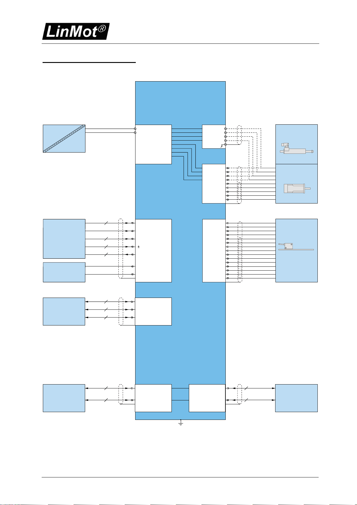
Connector Overview
24...72V DC
PGND
X1 X2 (HC)
X14 X13
X3
SUPPLY
3x400VAC
230VAC
115VAC
PH1+
PH1-
PH2+
PH2-
BRUSHLESS
DC MOTOR
LINEAR MOTOR
PH1+
PH1-
PH2+
PH2-
SIN
COS
TEMP.
+SV
GND
MOTOR SUPPLY
B1100-GP(-HC/-XC)
OPTIONAL EXTERNAL
POSITION SENSOR
A+
A-
B+
B-
Z+
Z-
U+
U-
V+
V-
W+
W-
ENC
ALARM
+5VDC
RS232 INTERFACE
CONFIGURATION
RS: 9,6-118kBaud
CAN: CANOPEN
DEVICENET
MAX: 500kBaud
RS232/RS485
RS485
CAN
3
4
X5
2
6
6
6
MACHINE
CONTROLLER PLC, IPC
LOGIC SUPPLY
STEP/DIR/ZERO
0...10V
INPUTS 1-6
10V
OUTPUTS 1-6
+24VDC
GND
2
4
2
X8
COMMUNICATION
INTERFACE
RS422/RS485
CANOPEN
DEVICENET
RS485
CAN
4
2
X7
RS485
CAN
COMMUNICATION
INTERFACE
RS422/RS485
CANOPEN
DEVICENET
Typical servo system B1100-XX-YY: Servo controller, motor and power supply.

Quick Start Guide B1100-VF
NTI AG, LinMot Quick Start Guide E1100-VF 06.12.2007 Page 5/16
Getting Started Current Command Mode
Connect the motor to the controller, wire at least the motor power supply on X1 and the
24VDC logic supply on X14.
Wire the differential analog current command input to X14.8/X14.21.
Wire the position encoder signals from the X13 connector to the superior control system.
Wire the state machine control lines according the configuration. For the quick start
configuration use the following:
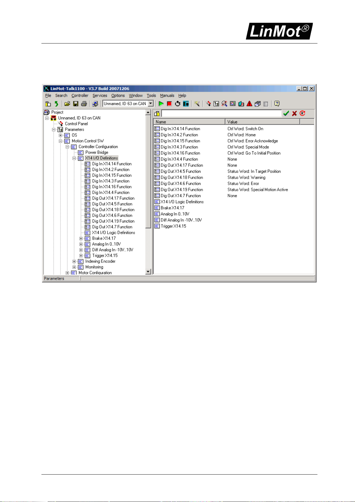
Descriptor IO type Configured Function
X14.14 Input Ctrl Word: Switch On
X14.2 Input Ctrl Word: Home
X14.15 Input Ctrl Word: Error Acknowledge
X14.3 Input Ctrl Word: Special Mode
X14.16 Input Ctrl Word: Go To Initial Position
X14.5 Output Status Word: In Target Position
X14.18 Output Status Word: Warning
X14.6 Output Status Word: Error
X14.19 Output Status Word: Special Motion Active
Alternatively to the digital IO control of the state machine and error
handling you can use a B1100-GP controller and do this over a serial bus
interface (CanOpen, DeviceNet or LinRS). This offers deeper integration
into your superior control system.
Connect your configuration PC using a 1:1 serial RS232 cable (female/female) with the servo
controller X5.
Switch on the 24V logic supply.
Start the LinMot-Talk1100 software.
Login the servo controller.
Quick Start Guide B1100-VF
Page 6 of 16 Quick Start Guide B1100-VF 06.12.2007 NTI AG/ LinMot/
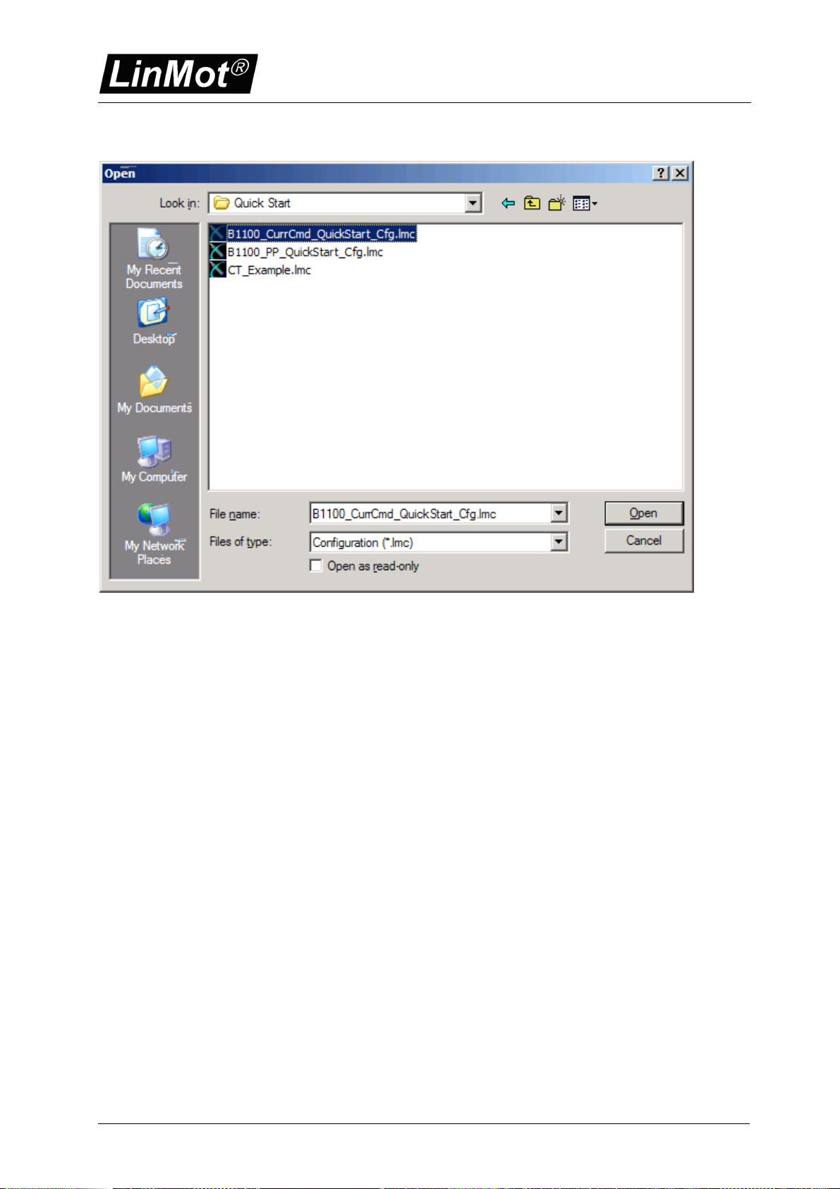
Import the B1100_CurrCmd_QuickStart_Cfg.lmc configuration file:
The following description is a short tour through the imported configuration.
Quick Start Guide B1100-VF
NTI AG, LinMot Quick Start Guide E1100-VF 06.12.2007 Page 7/16
IO Configuration
In the quick start configuration the digital inputs and outputs are configured as shown:

Quick Start Guide B1100-VF
Page 8 of 16 Quick Start Guide B1100-VF 06.12.2007 NTI AG/ LinMot/
The differential analog voltage input is configured as a current command input:

Quick Start Guide B1100-VF
NTI AG, LinMot Quick Start Guide E1100-VF 06.12.2007 Page 9/16
The scaling is done with the 10V current value and may be adapted regarding the maximal
current of your servo controller and the maximal current of your motor:

Quick Start Guide B1100-VF
Page 10 of 16 Quick Start Guide B1100-VF 06.12.2007 NTI AG/ LinMot/
Also the 0V offset adjustment could be done here:
In the next step the state machine is set to the special mode “Current Command Mode”:
Quick Start Guide B1100-VF
NTI AG, LinMot Quick Start Guide E1100-VF 06.12.2007 Page 11/16
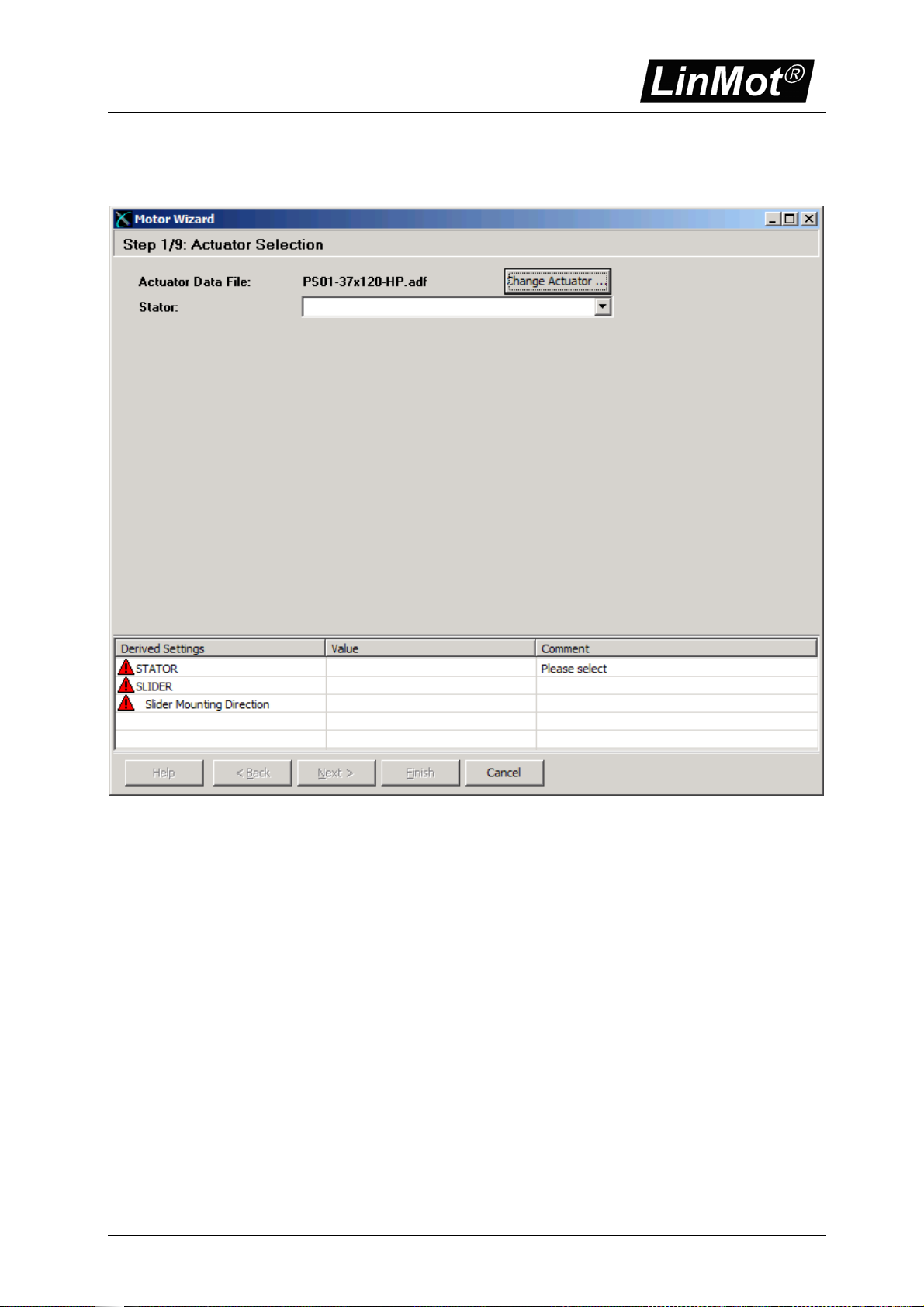
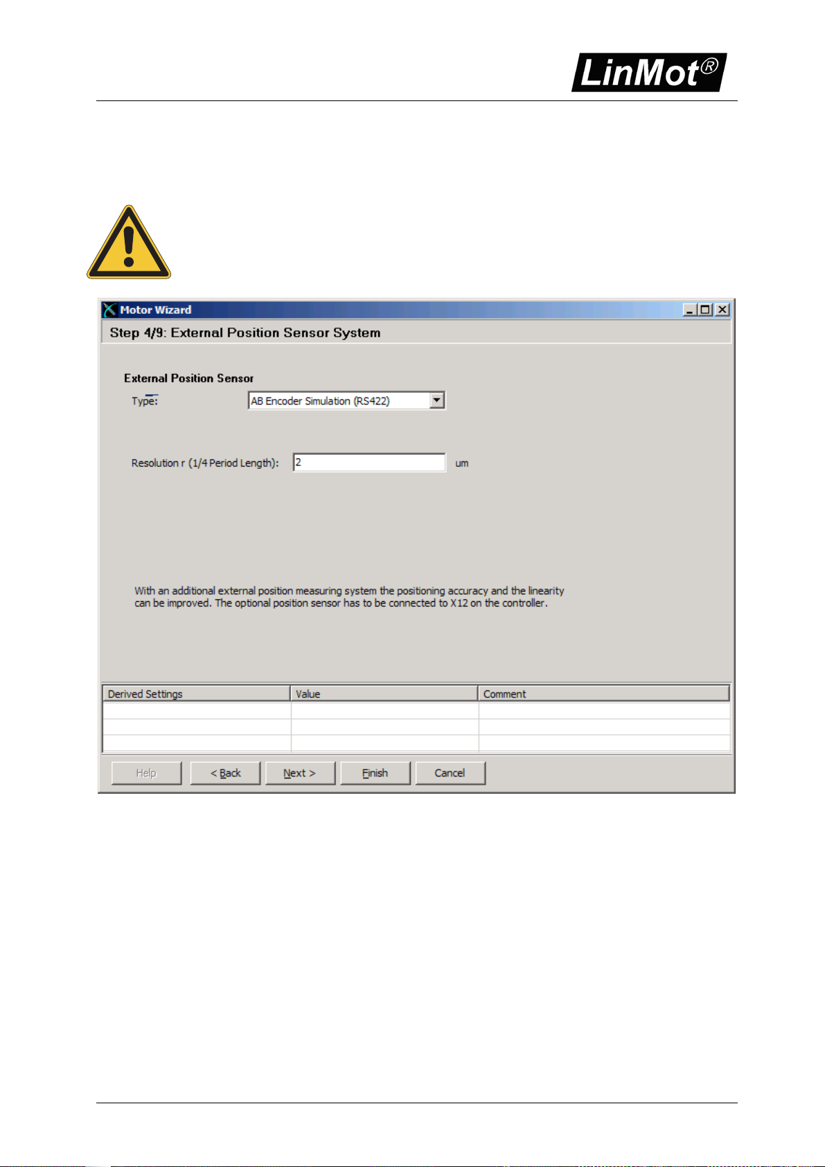
Now the motor can be configured with the motor wizard. The motor wizard guides you through
the configuration:

Quick Start Guide B1100-VF
Page 12 of 16 Quick Start Guide B1100-VF 06.12.2007 NTI AG/ LinMot/
Quick Start Guide B1100-VF
NTI AG, LinMot Quick Start Guide E1100-VF 06.12.2007 Page 13/16
If you use the encoder simulation you can configure it at the external position sensor system
section. As resolution you may configure a multiple of 0.1um, recommended values are 2um
5um 10um, which should be a good selection for most applications.
A too small resolution value may reduce the maximal speed in operation! For
secure operation, the maximal velocity/resolution should not be greater than
2MHz. E.g. 4m/s/2um = 2MHz, which means 4m/s is the maximal save
operation speed for 2um sensor simulation resolution.
When the motor wizard is finished all the needed configuration is made. The system is now
ready for operation. Power on the motor supply.
Quick Start Guide B1100-VF
Page 14 of 16 Quick Start Guide B1100-VF 06.12.2007 NTI AG/ LinMot/
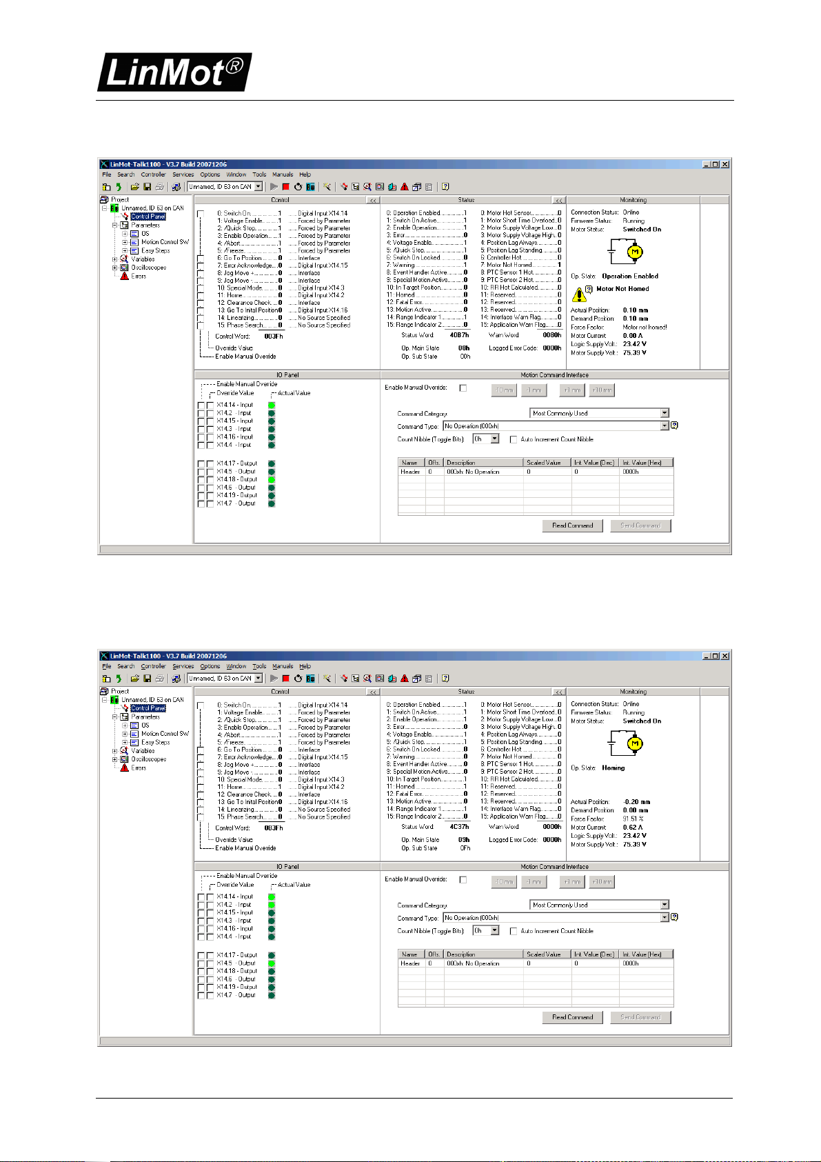
Set the input on X14.14 high, this enables the position control of the motor:
Now set the input on X14.2 to start the homing sequence. Wait until the warning on X14.8
disappears and the in target position on X14 5 is set. This indicates that the homing sequence
has been completed.

Quick Start Guide B1100-VF
NTI AG, LinMot Quick Start Guide E1100-VF 06.12.2007 Page 15/16
Set the input on X14.2 low to complete the homing.
By setting the input on X14.3 the current command interface will be activated!
Before activating the superior position control loop, make sure the position
control loop in your superior system is initialised correctly and the position
feedback direction is correct! Otherwise the motor will accelerate in any
direction and crash to a limit!
If an error occurs, the output on X14.6 will go high. It can be acknowledged by a rising edge on
the input X14.15.

Quick Start Guide B1100-VF
Page 16 of 16 Quick Start Guide B1100-VF 06.12.2007 NTI AG/ LinMot/
Contact Addresses
-----------------------------------------------------------------------------------------------------------------------------
SWITZERLAND NTI AG
Haerdlistr. 15
CH-8957 Spreitenbach
Sales and Administration: +41-(0)56-419 91 91
office@linmot.com
Tech. Support: +41-(0)56-544 71 00
Fax: +41-(0)56-419 91 92
Web: http://www.linmot.com/
-----------------------------------------------------------------------------------------------------------------------------
USA LinMot, Inc.
5750 Townline Road
Elkhorn, WI 53121
Sales and Administration: 877-546-3270
262-743-2555
Tech. Support: 877-804-0718
262-743-1284
Fax: 800-463-8708
262-723-6688
Web: http://www.linmot-usa.com/
-----------------------------------------------------------------------------------------------------------------------------
Please visit http://www.linmot.com/ to find the distribution near you.
Smart solutions are…
Other manuals for B1100-VF
1
This manual suits for next models
2
Table of contents
Other LinMot Recording Equipment manuals


