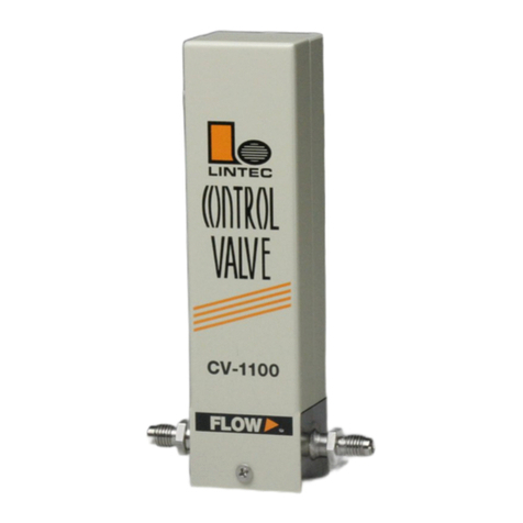
Lintec CV-3000 Series User manual

LN0540E2110B0
Piezo Control Valve
Instruction Manual
CV-3000 Series
Safety Precautions
Incorrect handling may cause death or injury
(1) Before connecting the fittings, check that no damage or defects are found on
the fittings. Make connections properly and make sure that a leak test is
conducted before actual operation to prevent fluid from leaking into the
atmosphere (Hereafter, the measured fluid is called “gas” or “fluid”).
(2) DO NOT apply any corrosive fluid tomaterials exposed to gas. Corrosion may
cause gas to leak into the atmosphere.
(3) This device is not designed as an explosion proof structure. DO NOT use this
device in a place where explosion-proof structures are required. Doing so may
cause fire or explosion.
Incorrecthandlingmaylead tomedium orslight injuryormay
causedamageto,orlossof,facilitiesorequipment
(1) Observe the precautions listed in the WARNING (above).
(2) Strictly observe the electrical specifications. Not doing so may cause fire,
damage to sensors or malfunction.
(3) This device is not designed to be waterproof. DO NOT locate this device
outdoors or in a place where it may besplashed with water.Doing so may cause
fire, trouble, or malfunction of the device.
(4) DO NOT modify this device. It may cause fire or other problems.
(5) While a power supply is applied to the device, +15VDC and -15VDC must be
applied simultaneously. If only +15VDC or -15VDC is applied, electronic
circuits will become unstable and it may cause a malfunction.
(6) This device is not designed to handle hot swap. Please avoid attaching and
removing the power supply connector and interface connector with the power
switched on. Attachment and/or removal with the power on may result in
failure of the device.
(7) This device is a precious device, please handle it carefully. Dropping down or
handling it carelessly will cause damage. Please use assist instrument while
moving or setting the device.
(8) Regular maintenance is recommended for steady use of this device
(Recommended proofreading frequency is once a year).
1. Introduction
This manual explains basic operation of the piezo control valve CV-3000 series
(Hereafter, it is called "CV"). Please read through this manual carefully to
familiarize yourself with the features of this device.
2. Summary
The CV is a high-speed response valve for controlling the flow rate or pressure of
gas by the control input from an external device.
3. Features
The CV is the following features.
(1) Equipped with a high-speed, high-performance piezoelectric actuator.
(2) Superior corrosion resistant sealing materials make maintenance easy.
(3) By using a metal case and various types of filters, steady operation can achieve
even in an environment of high-frequency noise and stationary magnetic field.
(4) RoHS compliant
4. Structure
The CV consists of piezo valve, control circuit, piezo driver.
5. Specification / Dimensions
(1) Specification
Name
Piezo Control Valve
Model
CV-3102
CV-3202
Standard flow rate in
nitrogen
~5LM
~10LM
Valve operation mode
Normally open valve / Normally closed valve
Internal surface treatment
No treatment / Precision polishing (LEP)
Minimumcontrollableflowrate
2%F.S.
Settinginputofvalve-opening
0 to 5VDC
Response time
Less than 0.5 second
Operating differential
pressure
50 to 300kPa(D)
Normally open 50 to 300kPa(D)
Normally closed 100 to 300kPa(D)
Maximum operating
pressure
300kPa(G)
Withstanding pressure
1MPa(G)
Operating / Storage
temperature & Humidity
0 to 50ºC·0 to 80%RH (Condensation should be avoided)
Leak integrity
Less than 1×10-11Pa · m3/sec (He)
Mounting direction
Free
Wetted materials
Stainless steel 316L, PCTFE, Au
Seal Materials
Au
Actuator
Piezoelectric actuator
Fittings
6.35VCR
Power supply
+15VDC±3% : 50mA -15VDC±3% : 50mA
Weight
Approx. 700g
(2) Dimensions
6. Ordering information
CV-3*02 –MO –4VR5 AAA00 –dd –ee –ff
[1] [2] [3] [4] [5] [6] [7]
[1] Series model: CV: Control Valve
CV-3102, CV-3202
[2] Valve mode
NO: Normally open (No treatment), MO: Normally open (LEP)
NC: Normally close (No treatment), MC: Normally close (LEP)
[3] Fitting
4VR5:6.35mm VCR86
※ Please consult for more information.
[4] Optional
Default setting is labeled
“AAA00”.
Please consult for more information.
[5] Gas type
[6] Full scale flow rate
[7] Flow rate unit
CCM, LM

7. Connection
(1) Analog interface connector
Mounted connector : D-Sub 9 pin(male)
Pair connector : D-Sub 9 pin(female) (Fixed size of screw : M3)
Pin No.
Single name
Function
1
Valve on-off input (Note1)
+15VDC: OPEN, -15VDC: CLOSE
2
N.C.
N.C.
3
Power supply input +15VDC±3%
Power supply (plus) 50mA
4
Power supply COMMON
COMMON ±15VDC
5
Power supply input -15VDC±3%
Power supply (minus) 50mA
6
Setting input of valve-opening voltage
(Hi) 0 to 5VDC
Setting voltage plus side 0 to 5VDC
7
N.C.
N.C.
8
Setting input of valve-opening voltage
(Lo) 0 to 5VDC
Setting voltage minus side 0 to 5VDC
9
N.C.
N.C.
Note1)Inputimpedance offlow rate settingsignalis 100kΩ. Valve override impedance is 100kΩ.
·Theinitialflowrate settinginputis thesingle endinputmode. Pleasechangethe sideswitchinto
thelowerpositionwhenyou use the quasi-differentialinputmode.
·Pleasedo notconnectanythingwithN.C..
(2) Input switch
The toggle switch on the side of the CV is the selection switch for changing the
input setting mode. The single end mode is the upper position. The quasi-
differential input mode is the lower position.
1) Quasi-differential input
Use the quasi-differential input mode when both the COMMON of the power
supply and the COMMON of the setting signal make a common. Using the CV
in the single end mode will result in voltage error in the COMMON due to signal
transportation.
2) Single end input
Use the single end mode when both the COMMON terminal of the CV power
supply and the COMMON terminal of the setting signal are in a floating condition.
8. Valve characteristics
(1) Flow rate Characteristics
The relation between the setting voltage and the flow rate of the CV is not linear,
as shown in the figure. Also, the piezoelectric actuator exhibits hysteresis.
Therefore care should be taken if the CV is used in the open-loop mode. The valve
fully closes with zero 0VDC, and fully opens with five 5VDC of the valve setting
voltage, for both normally open and normally closed valves.
(2) Flow range
The maximum flow range isnot accurate. It changesgreatly depending on the type
of fluid, the pressure, and the environmental temperature, etc.
10. Operation
(1) Procedure
1) This product is packed in a clean room before shipment. Please break the
seals in a clean room after taking it out of its box.
2) Check the gas type and flow rate, and check the direction of the gas flow
and the CV before installation.
3) Check for gas leaks from the tubing with a helium (He) leak detector.
4) Connect the interface connectors according to the Connector tale.
5) Power requirements are +15VDC: 50mA and -15VDC: 50mA. Check the
voltage, polarity, and capacitance of the power supply voltage.
6) Turn on power supply and let the equipment warmup for at least 5 minutes
(Recommended time: 30min).
7) Complete shut off cannot be achieved with the CV. If complete shut off is
desired, a shut-off valve should be installed.
8) When a highly reactive gas is used, thoroughly purge all foreign matter
from the tubing and the CV before operation.
9) When contaminated gas is used, install a filter at the equipment inlet.
10)Use the CV within the range of the operating temperature (5 to 50°C).
11)Donotswitchthepowersupplyonandoffwithinonesecond.Itmaycausefailure.
12)When it is used as a feedback control of flow rate and pressure, the operation
output voltage of the PID controller should be 0 to 5 VDC. Choose a device with
output voltage of 0 to 5 VDC.
13)When using the Lintec MFC power supply, the built-in power supply and signal
setting generator make it easy to set up a system like an MFC.
(2) Valve control signal
The CV features a forced valve open/close input function.
The connector pin No.1 is used to input the internal valve open/close signal.
By inputting this signal, a forced opening/closing of the internal valve can be
performed without depending on the value of the flow rate preset signal.
When +15VDC is input: fully open
When –15VDC is input: fully closed.
11. Product warranty
(1) Period
This product is guaranteed for a period of 1 year from date of shipment. Defects
are repaired according to the following regulations.
(2) Scope
Warranty coverage is restricted to this product only. Any other damage caused
by this product is not covered.
(3) Disclaimer facts
The following repairs are not covered by the warranty:
1) Failure caused by by-product of fluid used.
2) Failurecausedbymisuse(includingcarelessoperation)orincorrectrepairormodification.
3) Failure caused by dropping after purchasing.
4) Failure caused by a natural disasters.
Even if the warranty period isstill in effect, the following items may not be repaired.
1) When the kind of fluid used in the product is unclear.
2) The product is returned with fluid remaining inside and safety cannot be
confirmed.
This device is a precision instrument. Control may become unstable if electric
noise, temperature change of fluid, pulsation of fluid pressure etc. occurs.
Please be forewarned.
This instruction manual is subject to revision without notice.
http://www.lintec-mfc.co.jp
CorporateHeadquarters
4-1-23Sekinotsu,OtsuCity,ShigaPref.520-2277,Japan
TEL. +81-(0)77-536-2210FAX.+81-(0)77-536-2215
TokyoBranchOffice
3FHattoriBuild.,4-30-14YotsuyaShinjyuku-kuTokyo160-0004, Japan
TEL. +81-(0)3-5366-2801FAX.+81-(0)3-3341-3513
印加電圧
流量
Setting
Flow rate
This manual suits for next models
2
Other Lintec Control Unit manuals
Popular Control Unit manuals by other brands
Trane
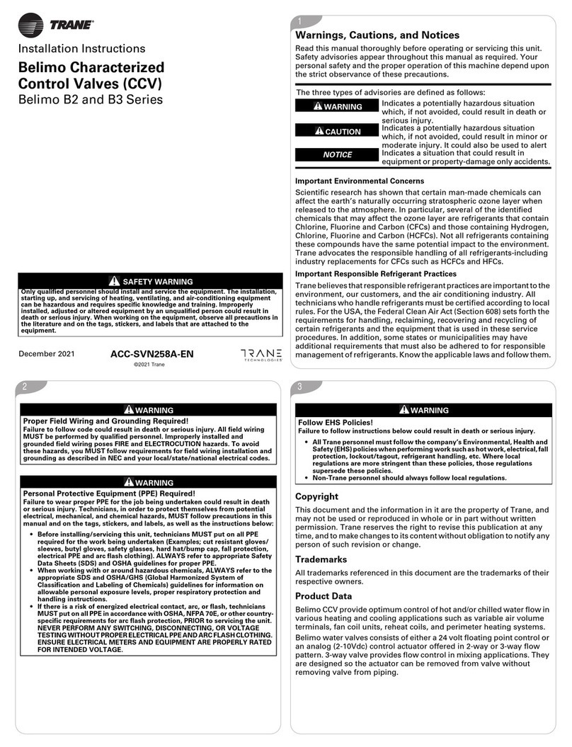
Trane Belimo B2 Series installation instructions
elsner elektronik
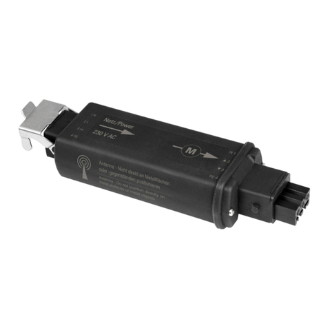
elsner elektronik RF-MSG-ST IP54 Technical specifications and installation instructions
Bradley
Bradley S90-252 HFP Adjustment Instructions and Parts List

Seav
Seav LG 2215TC manual
KBR
KBR multisio 1D4-4RO ISO operating instructions
Eaton
Eaton SmartWire-DT SWD Series manual

Toshiba
Toshiba PA912 instruction manual

SP Controls
SP Controls PixiePlus PXE-DCM PLUS installation guide
Nittan
Nittan EVA-SCM-SCI instruction manual
Frequency Central
Frequency Central Looking glass manual

Berthold
Berthold castxpert LB 452 operating manual

ICP DAS USA
ICP DAS USA WISE-5801-MTCP quick start guide
