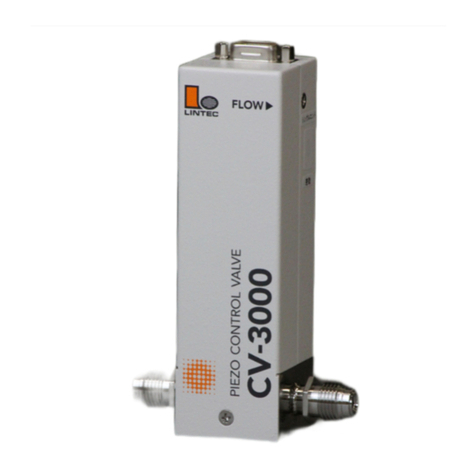
Lintec CV-1000 Series User manual

LN0099E2201G0
Solenoid Control Valve
Instruction Manual
CV-1000 Series
Safety Precautions
Incorrect handling may cause death or injury
(1) Before connecting the fittings, check that no damage or defects are found on
the fittings. Make connections properly and make sure that a leak test is
conducted before actual operation to prevent fluid from leaking into the
atmosphere (Hereafter, the measured fluid is called “liquid” or “fluid”).
(2) DO NOT apply any fluids corrosive to the wetted materials. Corrosion may
cause fluid to leak into the atmosphere. Check the fluid type to be used in advance.
(3) This device is not designed as an explosion proof structure. DO NOT use this
device in a place where explosion-proof structures are required. Doing so may
cause fire or explosion.
Incorrecthandlingmaylead tomediumor slightinjuryormay
causedamageto,orlossof,facilitiesorequipment
(1) Observe the precautions listed in the WARNING (above).
(2) Strictly observe the electrical specifications. Not doing so may cause fire,
damage to sensors or malfunction.
(3) This device is not designed to be waterproof. DO NOT locate this device
outdoors or in a place where it may besplashed with water. Doing so may cause
fire, trouble, or malfunction of the device.
(4) DO NOT modify this device. It may cause fire or other problems.
(5) This device is not designed to handle hot swap. Please avoid attaching and
removing the power supply connector with the power switched on. Attachment
and/or removal with the power on may result in failure of the device.
(6) This device is a precious device, please handle it carefully. Dropping down or
handling it carelessly will cause damage. Please use assist instrument while
moving or setting the device.
(7) Regular maintenance is recommended for steady use of this device
(Recommended proofreading frequency is once a year).
1. Introduction
This manual explains basic operation of the solenoid control valve CV-1000 series
(Hereafter, it is called "CV"). Please read through this manual carefully to
familiarize yourself with the features of this device.
2. Summary
The CV is a liquid control valve equipped with a solenoid actuator. It can operate
as a liquid mass flow controller by combining it with a liquid mass flow meter
(hereinafter referred to as "LM"). This device is separated into 2 types depending
on the way of the connector is attached. Because this device does not include a
built-in valve control circuit, input is made directly to the solenoid actuator. When
using this device in combination with the LM, please check the power supply
voltage and current.
3. Features
The CV is the following features.
(1) Equipped with a high-speed, high-performance solenoid actuator.
(2) Superior corrosion resistant sealing materials make maintenance easy.
(3) By using a metal case and various types of filters, steady operation can achieve
even in an environment of high-frequency noise and stationary magnetic field.
(4) RoHS compliant
4. Specification / Dimensions
(1) Specification
Name
Solenoid Control Valve
Model
(Both of models at the right are same spec.)
CV-120*-NC
CV-1100A (Until 2010)
Flow rate range
C2H5OH
~20g/min
H2O
~10g/min
Operating pressure
(When pairing with LM)
100 to 300 kPa
Valve operation mode
Normally closed
Maximum operating pressure
300 kPa(G)
Withstanding pressure
1 MPa(G)
Operating / Storage temperature &
Humidity
0 to 50 ºC / 0 to 80%RH (No dew)
Materials exposed to liquid
Stainless steel 316L, Au, PTFE
Seal Materials / Inner treatment
Au / Machine finish
Leak integrity
Less than 1×10-11 Pa·m3/sec (He)
Connector
HR10-7R-4P (Hirose)
Control voltage / Current
0 to 15 VDC / 200mA Max
Mounting direction
Free
Accessories
CC-LV-3-3M (3000mm) ×1pc
Weight
Approximately 750g
(2) Dimensions (CV-1204-NC-2VR7AAA00)
5. Ordering information
CV-120* –NC –2VR7 AAA00
[1] [2] [3] [4]
[1] Series model: CV: Control Valve
CV-1204 (Connector : Upward)
CV-1207 (Connector : Downstream side)
[2] Valve mode
NC: Normally close (No treatment)
[3] Fitting
2VR7 : 3.2 mm (1/8”) VCR male Fitting Distance 77 mm
2SW9 : 3.2 mm (1/8”) SWL male Fitting Distance 92.4 mm
4SW9 : 6.35 mm (1/4”) SWL male Fitting Distance 88.4 mm
※ Please consult for more information.
[4] Optional
Default setting is labeled
“AAA00”.
Please consult for more information.
Connector
HR10-7P-4S(73)(HRS)
Connector
HR10-7P-4P(73)(HRS)
13
145
5.3
(28.5)
Cable
CC-LV-3
7
187
CV-1100
20 37 20
77
32
9.5 18 9.5 2xM4 Depth 5
3.2(1/8)VCR male

6. Connection
The solenoid valve used in this device is connected directly with the connector.
There is no polarity.
Mounted connector: HR10-7R-4P (Hirose)
Pair connector: HR10-7R-4S (Hirose)
Pin No.
Signal name
1
Solenoid terminal
2
3
N.C.
4
7. Flow rate characteristics
Hysteresis due to magnetic saturation is a characteristic of solenoid valves. For
this reason, the voltage/flow rate characteristics are, as shown in the figure below,
not linear. This does not pose a problem when used in combination with the LM
as a feedback system, but care needs to be taken when using this device singularly
in an open loop.
8. Operation
(1) When using in combination with the LM (liquid control)
When using with the LM liquid mass flow meter please connect this device and
the LM with the cable provided. The LM has built-in control circuitry for the
control of the CV so that additional wiring is not necessary.
Please refer to “Instruction manual of LM” for details.
(2) When using this device only
When using this device in combination with LM or singularly, please take note
of the following items.
1) Use a control voltage of within 15VDC. The current consumption at an applied
voltage of 15VDC isa maximum 200mA.
2) Thecontrolvalveisasolenoidactuator.Becausethisresultsinaninductanceload,
pleaseinstall a reverse current prevention circuit wherenecessary.
3) Thevoltage/flowratecharacteristicsarenotlinear.Additionally,hysteresisisalso
present.
(3) Procedure
1) Thisproduct is packaged in a clean room before shipment. Please break seals
in a clean room after taking it out of packing box.
2) Check the liquid type and flow rate, and the direction of the liquid flow
before installation.
3) Check the leaks from tubing with a helium leak detector.
4) Connect the analog interface connectors according to the connector table in
“Instruction manual of LM”. Please use CC-LV-3 to connect LM and CV.
5) Power requirements are +15VDC:150mA and -15VDC:200mA. Check the
voltage, polarity and capacitance of power supply voltage.
6) Turn on the power supply and let the equipment warm up for 5 minutes
(Recommendedtime :30min.).
7) Adjustthe zeropointbypressingthezero-adjustmentswitchlocated onthetopof
theequipment.Beforezeroadjustment,checkthatliquidisnotbeingsupplied
and the device was warmed up for 30 minutes or more in order to ensure
sensorstability.
8) Input the flow rate setting signal and supply liquid with required differential
pressure to the LM. The LM will begin to control the liquid flow in proportionto
the preset voltage. Full-scale voltage is 5VDC. Maximum input voltage is
±15.5VDC.
9) When the output flow rate signal is used, the tolerance voltage of the external
device should be more than ±15.5VDC. When it’s connected, the output
valve may be within the range of the maximum voltage ±15.5VDC.
10) When a highlyreactiveliquid is used, please thoroughly purgethetubing and
the LM before operation.
11) When contaminated liquid is used, install a filter at the equipment inlet.
12) Use the LM within the range of the operating temperature (15 to 35°C), and
keep it at the same temperature with the fluid. If used in any other
environments that do not meet the above-mentioned requirements, it is
unable to measure the flow rate accurately. And it may cause a failure.
13) Do not switch the power supply on and off within one second. It may cause a
failure.
14) Helium gas is recommended for pushing the liquid. If any other gas isused, the
dissolved gas will produce bubbles, and it may make the control unstable.
9. Product warranty
(1) Period
This product is guaranteed for a period of 1 year from date of shipment. Defects
are repaired according to the following regulations.
(2) Scope
Warranty coverage is restricted to this product only. Any other damage caused
by this product is not covered.
(3) Disclaimer facts
The following repairs are not covered by the warranty:
1) Failure caused by by-product of fluid used.
2) Failurecausedbymisuse(includingcarelessoperation)orincorrectrepairormodification.
3) Failure caused by dropping after purchasing.
4) Failure caused by a natural disasters.
Even if the warranty period is still in effect, the following items may not be repaired.
1) When the kind of fluid used in the product is unclear.
2) The product is returned with fluid remaining inside and safety cannot be
confirmed.
This device is a precision instrument. Control may become unstable if electric
noise, temperature change of fluid, pulsation of fluid pressure etc. occurs.
Please be forewarned.
This instruction manual is subject to revision without notice.
http://www.lintec-mfc.co.jp
CorporateHeadquarters
4-1-23Sekinotsu,OtsuCity, ShigaPref.520-2277,Japan
TEL. +81-(0)77-536-2210FAX.+81-(0)77-536-2215
TokyoBranchOffice
3FHattoriBuild.,4-30-14YotsuyaShinjyuku-kuTokyo160-0004,Japan
TEL. +81-(0)3-5366-2801FAX.+81-(0)3-3341-3513
印加電圧
流量
Flow rate
Setting
This manual suits for next models
3
Other Lintec Control Unit manuals
