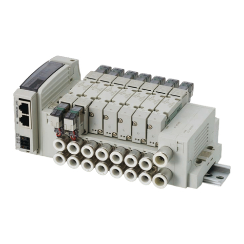
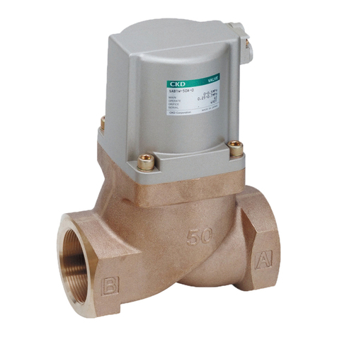
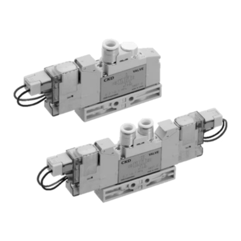
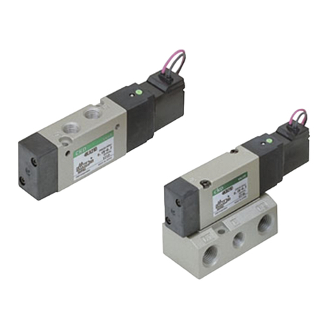
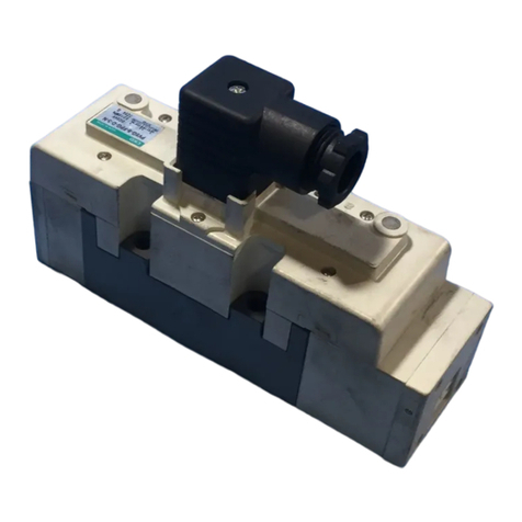
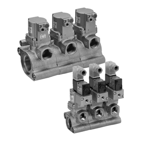
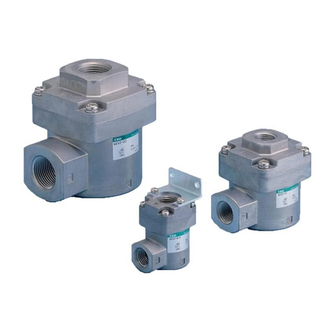
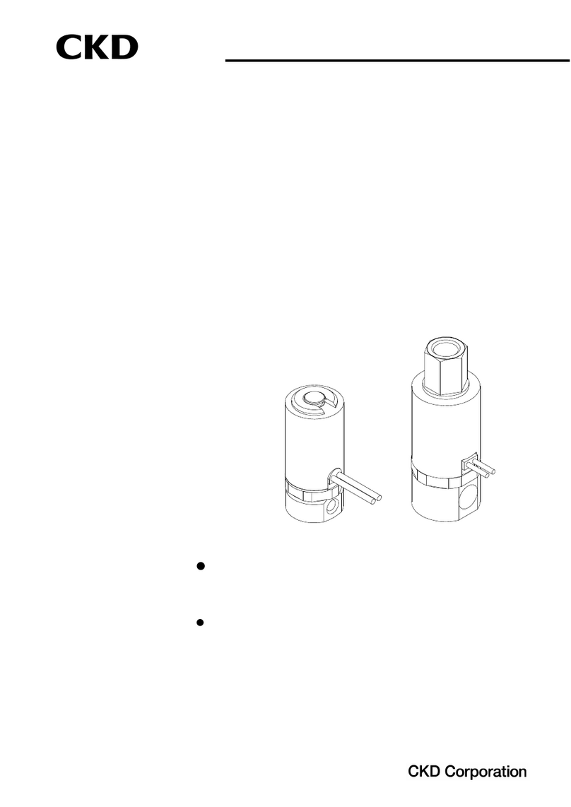
CKD CVE2 Series Installation and operating manual

AP/
AD
HNB/G
USB/G
FAB/G
FGB/G
FVB
FWB/G
FHB
FLB
AB
AG
CHB/G
MXB/G
SAB/
SVB
HVB/
HVL
For
dry air
NP/NAP/
NVP
PD/FAD/
PJ
CVE/
CVSE
CPE/
CPD
Custom
order
Medical
analysis
Other G.P.
systems
APK/
ADK
Explosion
proof
Coolant valve
Air operated 2, 3 port valve
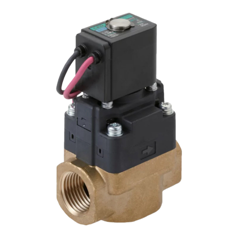
This is a reliable 2, 3 port coolant
valve with cylinder drive method.
This valve for tool machine cutting oil
or coolant control incorporates a
metal seal to prevent the entry of
cutting chips, abrasive grains and
foreign debris, and ensures highly
reliable control.
The air operated type and solenoid
valve mounted type are available.
These can be used in precise
machines.
Overview
High corrosion resistant
materials
Cast iron body, and stainless steel
metal seal used in valve seat. NBR
or FKM packing seal can be
selected. Materials optimum for
coolant are used.
Certain operation
Certain operation is enabled with
external pilot air operated cylinder.
Water hammer prevented
(Only 2 port valve)
Resistant to foreign matter
A metal seal is used.
Usable in flammable
environment.
(Air operated type)
Features
CVE2/CVSE2
CVE3/CVSE3
(Coolant valve)
Air operated 2, 3 port valve (coolant control)
䡵For coolant
Series variation 700
Safety precautions 702
䢇Product introduction 706
Low pressure (0.5 MPa and 1.0 MPa), 2 port valve
䢇Air operated type CVE2, CVE22-05/10 708
䢇Solenoid valve mounted type CVSE2, CVSE22-05/10 708
Medium pressure (1.6 MPa and 3.0 MPa), 2 port valve
䢇Air operated type CVE2, CVE22-16/30 718
䢇Solenoid valve mounted type CVSE2, CVSE22-16/30 718
High pressure (7.0 MPa), 2 port valve
䢇Air operated type CVE2, CVE22-70 726
䢇Solenoid valve mounted type CVSE2, CVSE22-70 726
Medium/high pressure (3.5 MPa and 7.0 MPa), 3 port valve
䢇Air operated type CVE3-35/70 732
䢇Solenoid valve mounted type CVSE3-35/70 732
Low pressure (0.3 MPa), 3 port valve
䢇Air operated type CV3E 744
䢇Solenoid valve mounted type CVS3E 744
Electronic Catalog file list 746
CONTENTS
Always read the precautions in the Introduction and
page 702 before starting use.
699

700
Category
Air operated type
Solenoid valve mounted type
Air operated type
Solenoid valve mounted type
Air operated type
Solenoid valve mounted type
Air operated type
Solenoid valve mounted type
Air operated type
Solenoid valve mounted type
Air operated type
Solenoid valve mounted type
Air operated type
Solenoid valve mounted type
Air operated type
Solenoid valve mounted type
Working
pressure
range
MPa
CVE2-***-05
CVSE2-***-05
CVE2-***-10
CVSE2-***-10
CVE2-***-16
CVSE2-***-16
CVE2-***-30
CVSE2-***-30
CVE2-***-70
CVSE2-***-70
CV3E-***-03
CVS3E-***-03
CVE3-***-35
CVSE3-***-35
CVE3-***-70
CVSE3-***-70
Model
No. of port
䢇
䢇
䢇
䢇
䢇
䢇
䢇
䢇
䢇
䢇
䢇
䢇
䢇
䢇
䢇
䢇
䢇
䢇
䢇
䢇
䢇
䢇
䢇
䢇
䢇
䢇
䢇
䢇
Rc3/8 Rc1/2
0 to 0.5
0 to 1.0
0 to 1.6
0 to 3.0
0 to 7.0
0 to 0.3
0 to 3.5
0 to 7.0
2 port
3 port
Low pressure
Medium pressure
Medium pressure
High pressure High pressure
Low pressure
Series variation Air operated 2, 3 port valve (coolant control)
(Coolant valve)

701
AP/
AD
HNB/G
USB/G
FAB/G
FGB/G
FVB
FWB/G
FHB
FLB
AB
AG
CHB/G
MXB/G
SAB/
SVB
HVB/
HVL
For
dry air
NP/NAP/
NVP
PD/FAD/
PJ
CVE/
CVSE
CPE/
CPD
Custom
order
Medical
analysis
Other G.P.
systems
APK/
ADK
Explosion
proof
Coolant valve
Air operated 2, 3 port valve
Port size
Rc3/4 Rc1 Rc1 1/4 32 flange 40 flangeRc1 1/2 Rc2 50 flange Page
䢇
䢇
䢇
䢇
䢇
䢇
䢇
䢇
䢇
䢇
䢇
䢇
䢇
䢇
䢇
䢇
䢇
䢇
䢇
䢇
䢇
䢇
䢇
䢇
䢇
䢇
䢇
䢇
䢇
䢇
䢇
䢇
䢇
䢇
䢇
䢇
䢇
䢇
䢇
䢇
䢇
䢇
䢇
䢇
䢇
䢇
䢇
䢇
䢇
䢇
䢇
䢇
䢇
䢇
䢇
䢇
䢇
䢇
䢇
䢇
䢇
䢇
65 flange
䢇
䢇
䢇
䢇
80 flange
䢇
䢇
䢇
䢇
708
708
708
708
718
718
718
718
726
726
744
744
732
732
732
732

702
(2)
Pre-lubrication - This series is pre-lubricated, so no lubricator
is required. However, once lubrication has been started, it
must be continued so that the lubricant is not used up. For
lubrication, use the turbine oil Class 1 ISO VG32 (#90) or
equivalent.
(3) Filter - Install a filter with a 5 μm or less filter element.
Design & Selection
CR circuit
Triode AC switch
Leakage
current
C
R
Solenoid valve
Programmable
controller side
Air operated 2, 3 port valve (coolant valve) (CVE/CVSE)
1. Safety designing
CAUTION
䡵Leakage current from other fluid control components
When operating the solenoid valve with a programmable
controller, etc., check that the output leakage current from the
programmable controller is within the following specifications.
Failure to observe this could lead to malfunctions.
䡵
CVSE Series cannot be used in an explosive gas atmosphere.
When using in an explosive gas atmosphere, change to the
CVE Series, and provide a separate explosion proof solenoid
valve on the pilot air circuit.
䡵If there are high levels of dust in the area, install a downward-
facing silencer or elbow joint on the exhaust port so that dust
does not enter.
䡵
When using in a place where water splashes on the valve, take
appropriate measures to protect it.
WARNING
2. Working fluid
WARNING
3. Working environment
4. How to use
䡵Working fluid
The compatibility has not been evaluated with all coolants.
Particularly, if coolant contains high levels of chlorine or
sulfur, materials used at wetted parts could be adversely
affected. Confirm the compatibility when making a selection.
Non-corrosive fluids refer to fluids that do not affect or are not
affected when they contact the valve's wetted part materials.
cast iron (nickel plating), stainless
steel, nitrile rubber or fluoro rubber,
and epoxy resin adhesive.
䡵External pilot air
(1) Drainage measures - Compressed air contains high levels
of drainage (water, oxidized oil, tar, foreign matter) that
can significantly reduce the reliability of pneumatic
components. As measures against drain, improve air
quality by dehumidifying with an after cooler or dryer,
removing foreign matter with a filter, and removing tar with
a tar removal filter, etc.
CAUTION
䡵Pilot air pressure
Use pilot air pressure in accordance with the specifications.
X
Y
P
Y
P
IN
Model no.
CVE2
CVE22
CVSE2/CVSE22
CVE3
CVSE3
Pilot operation
side supply port
Unit side
supply port
Note: Pipe the unit side supply port so that the arrow on the body matches
the fluid flow direction. If supplied in reverse, internal components
could be damaged when the valve operates.
CAUTION
1. Piping
䡵Do not pipe using the solenoid valve section. There is a risk
of damage. (For solenoid valve mounted type)
Installation & Adjustment
䡵When piping the CVE or CVSE Series, pay attention to the
supply ports on the unit and pilot operation sides.
Wetted part materials:
100 VAC : 3 mA or less
200 VAC : 1.5 mA or less
24 VDC : 1 mA or less
must be maintained.
Safety precautions
Always read this section before starting use.

703
AP/
AD
HNB/G
USB/G
FAB/G
FGB/G
FVB
FWB/G
FHB
FLB
AB
AG
CHB/G
MXB/G
SAB/
SVB
HVB/
HVL
For
dry air
NP/NAP/
NVP
PD/FAD/
PJ
CVE/
CVSE
CPE/
CPD
Custom
order
Medical
analysis
Other G.P.
systems
APK/
ADK
Explosion
proof
Coolant valve
Air operated 2, 3 port valve
䢇Model no.:
CVS2-CONNECTOR-F4-202936
Hexagon head 24
25
16
Pg9 G1/2
CAUTION
2. Wiring
WARNING
2. Assembling & disassembling
䡵Wiring of solenoid valve mounted type
(1) Refer to connections in pages 54 to 55 in the Introduction
when wiring to a DIN terminal box or T type terminal box.
(2) The size of the screw for the junction box outlets of the
DIN terminal box can be changed from Pg9 to G1/2
using the optional connector below.
䡵A spring is used in the cylinder cover. When
disassembling this type, the spring could pop
out and cause injuries, so take care.
The NC (normally closed) type 2 port valve has
a snap ring to prevent the spring from popping
out. Do not remove the snap ring.
(3) Coil direction can be changed 180˚. To reverse the
electrical connection direction, rotate only the coil. Do
not lose internal parts when removing the coil.
CAUTION
1. Maintenance & inspection
During Use & Maintenance
䡵Pilot air pressure
Use pilot air pressure in accordance with the specifications.
䡵If water hammer occurs when a 3 port coolant
valve for medium/high pressure operates,
reduce the noise as follows.
(1) Install a metering valve on the valve IN side, then adjust
the metering valve to reach the required flow.
If these countermeasures fail, contact CKD.
CVE/CVSESeries
Individual precautions

704
If the pilot solenoid valve has been disassembled, assemble it as follows.
䡵Assembling pilot solenoid valve
(for solenoid valve mounted type)
䡵
Gasket direction (for solenoid valve mounted type)
The gasket has an orientation. Check the orientation when reassembling.
䡵
Model no. of pilot solenoid valve (actuator assembly kit)
for CVSE
CVSE2-ACTUATOR–0 Rated voltage
–
Note 1: Indicate the coil option symbol in field *1.
Note 2: Consult with your CKD Sales Representative about the
solenoid valve (actuator assembly kit) for CVS3E.
*1
(1) Coil side
·Disassembling
Loosen the cross headed pan head machine screw, and lift up the
coil assembly.
The outer spring, plunger assembly and O ring can be removed.
·Reassembling
Set the parts in the sequence of the O ring, plunger assembly, outer
spring and coil assembly.
Tighten the cross headed pan head machine screw with a torque of
0.7 to 1.1 N·m.
(2) Cover side
·Disassembling
Loosen the flat headed cross cut screw, and remove the cover.
The valving element spring, valving element guide assembly and O
ring can be removed.
·Reassembling
Set the parts in the sequence of the O ring, valving element guide
assembly, valving element spring and cover. Tighten the flat headed
cross cut screw with a torque of 0.7 to 1.1 N·m.
Note 1: Do not lose the components such as springs during disassembly.
Note 2: The coil assembly direction can be changed 180˚. Loosen the
cross headed pan head machine screw to change the direction.
Note 3: Turbine oil is applied to the plunger as a lubricant.
Cross headed pan head
machine screw
Body assembly
Flat headed cross
cut screw
Valving element
guide assembly
Valving element
spring
Cover
O ring
O ring
Plunger assembly
Coil assembly
Outer spring
Note 2
CVSE22/CVSE3CVSE2
NO (normally open) type, 3 port valveNC (normally closed) type
Port R Port R
Gasket
CVE/CVSESeries
@

705
AP/
AD
HNB/G
USB/G
FAB/G
FGB/G
FVB
FWB/G
FHB
FLB
AB
AG
CHB/G
MXB/G
SAB/
SVB
HVB/
HVL
For
dry air
NP/NAP/
NVP
PD/FAD/
PJ
CVE/
CVSE
CPE/
CPD
Custom
order
Medical
analysis
Other G.P.
systems
APK/
ADK
Explosion
proof
Coolant valve
Air operated 2, 3 port valve
MEMO

Reducing energy loss!
Low pressure (0.5 MPa) to high pressure (7.0 MPa) is available with port size 10A to 80F.
Handling coolant needs with a wide range of products.
Low pressure loss, large flow rate coolant valve,
Pressure loss
50%reduction
Increased
flow rate
An ideal flow rate shape has been
pursued focusing on zero pressure loss.
Pressure losses have been
approximately halved compared to
conventional models. (Max. 59%
reduction, CKD comparison)
Pressure loss at 50 L/min. (0.5 MPa)
Comparison of Cv flow factor (0.5 MPa)
25
20
15
10
5
0
Pressure loss
Conventional
CVSE2 Series
50%
DOWN
55%
DOWN
CVSE2 Series 20A is same as
conventional 25A products!
20A
15A
20A
25A
5
Port size CVSE2 Series
Conventional
8
12
25A
Port size
Valve side mounted
low-wattage actuator
Reliable direct
acting
Reliable operation
Cylinder drive method using external
pilot air ensures reliable operation.
Low pressure loss
Ideal valve flow path shape
(registered design, patent pending)
Useful for various tool
machines and equipment
Low pressure loss
type 3 port valve
2, 3 port coolant valve
Resistant to cutting chips, etc.
The metal seal structure of this valve
prevents foreign matters such as
cutting chips and abrasive grains
from entering the valve.
Low pressure loss
type 2 port valve
[kPa]
706

45 types available.
Compatible designs with
conventional products
The product is compatible with
conventional products in face-to-face
dimensions and specifications, enabling
installation in existing facilities.
Easy installation
The actuator is mounted on the valve
side. It is generally smaller and easier to
install.
Current consumption is reduced by
50% with accurate direct-acting type
An accurate direct-acting solenoid valve
is used to open and close the valve.
Even still, the power consumption is
reduced to 2 W from the conventional 4 W.
Proposals for improving coolant devices
An optimum coolant system is realized by reviewing the valves and system.
Review of optimum value
for coolant discharge rate
Review of coolant valve
pressure loss
The coolant system’s optimum
circuit can be simulated with
sizing software.
Before
improvement
After
improvement
3 conventional
2 port valves
used
Low pressure loss
type 3 port valve
CVS3E
Downsizing of coolant pump
Achieving energy saving
coolant system
Low pressure loss
type 2 port valve
CVSE2
Series variation
Model
Port size
2 port valve
Low pressure
Medium pressure
High pressure
Medium pressure
Low pressure
High pressure
3 port valve
3 port valve
*1: A low-pressure shape is not incorporated for this model.
*2: Only Rc threaded type is available.
*2 *2 *2
*1 *1
*1 *1
AP/
AD
HNB/G
USB/G
FAB/G
FGB/G
FVB
FWB/G
FHB
FLB
AB
AG
CHB/G
MXB/G
SAB/
SVB
HVB/
HVL
For
dry air
NP/NAP/
NVP
PD/FAD/
PJ
CVE/
CVSE
CPE/
CPD
Custom
order
Medical
analysis
Other G.P.
systems
APK/
ADK
Explosion
proof
707
Coolant valve for low pressure
Air operated 2 port valve

Air operated 2 port valve for low pressure
(coolant valve)
CVSE2/CVSE22-05/10Series
CVE2/CVE22-05/10Series
708
Refer to Ending 17
for more details.
䢇
NC (normally closed) type, NO (normally open) type
䢇Port size: Rc3/8 to Rc2, 32 to 80 flange
䢇Low pressure 0.5 MPa, 1.0 MPa
JIS symbol
䢇
CVSE2 (solenoid valve mounted type)
: NC type
䢇
CVSE22 (solenoid valve mounted type)
: NO type
䢇CVE2 (air operated type)
: NC type
䢇CVE22 (air operated type)
: NO type
IN
XOUT
IN
YOUT
IN
POUT
IN
POUT
Common specifications for 0.5 MPa
Model no. CVE2/CVSE2 CVE22/CVSE22
Actuation
Working fluid
Fluid viscosity
Working pressure range
Withstanding pressure (water)
Fluid temperature
Ambient temperature
Valve seat leakage
Mounting attitude
Pilot air pressure
Water hammer (reference)
mm
2
/s
MPa
MPa
˚C
˚C
cm
3
/min.
MPa
MPa
Coolant, other non-corrosive fluids
500 or less
0 to 0.5
2.0
-10 to 60 (no freezing)
-10 to 60
20 or less (water)
Free
0.25 to 0.7
1 or less (with 10 m steel pipe, full pressure 0.5 MPa and flow rate 5 m/sec)
NC (normally closed) type NO (normally open) type
Electric specifications (solenoid valve mounted type common specifications)
Rated voltage
Apparent power
(VA)
Power consumption
(W)
Heat proof class
Protective structure
(IEC standards 529)
Holding
Starting
AC
DC
100 VAC (50/60 Hz), 110 VAC (60 Hz); 200 VAC (50/60 Hz), 220 VAC (60 Hz); 24 VDC
3.6 (50 Hz), 2.8 (60 Hz)
11 (50 Hz), 9 (60 Hz)
3.6 (50 Hz), 2.8 (60 Hz)
2.0
B
Grommet lead wire
DIN terminal box (Pg9)
T type terminal box (G1/2)
IPX2
IPX5
IPX5
*1:
Fluids that do not affect cast iron (nickel plating), stainless steel, nitrile rubber or fluoro rubber, and epoxy resin adhesive
*2: 1 cm
3
/min. or less for port size 10A (Rc3/8)
*3: Allowable voltage range must be within ±10% of the rated voltage.
Individual specifications for 0.5 MPa
Item
Model no. Weight (kg)
Pilot
port size
CVE2(2) CVSE2(2)
CVE2(2)/CVSE2(2)-10A-05
CVE2(2)/CVSE2(2)-15A-05
CVE2(2)/CVSE2(2)-20A-05
CVE2(2)/CVSE2(2)-25A-05
CVE2(2)/CVSE2(2)-32A-05
CVE2(2)/CVSE2(2)-32F-05
CVE2(2)/CVSE2(2)-40A-05
CVE2(2)/CVSE2(2)-40F-05
CVE2(2)/CVSE2(2)-50A-05
CVE2(2)/CVSE2(2)-50F-05
CVE2(2)/CVSE2(2)-65F-05
CVE2(2)/CVSE2(2)-80F-05
Rc3/8
Rc1/2
Rc3/4
Rc1
Rc1 1/4
32 flange
Rc1 1/2
40 flange
Rc2
50 flange
65 flange
80 flange
10
14
19
24
31
31
40
40
50
50
65
79
2.8
6.5
11
18
28
28
43
43
70
70
70
100
Rc1/8
0.35
0.6
1.2
1.8
2.7
5.3
4.4
7.0
6.5
9.6
19.5
24.0
0.45
0.7
1.3
1.9
2.8
5.4
4.5
7.1
6.6
9.7
19.5
24.0
(*2)
(*1)
Port size Orifice
(mm) Cv flow
factor

CVE2/CVSE2-05/10Series
@
709
AP/
AD
HNB/G
USB/G
FAB/G
FGB/G
FVB
FWB/G
FHB
FLB
AB
AG
CHB/G
MXB/G
SAB/
SVB
HVB/
HVL
For
dry air
NP/NAP/
NVP
PD/FAD/
PJ
CVE/
CVSE
CPE/
CPD
Custom
order
Medical
analysis
Other G.P.
systems
APK/
ADK
Explosion
proof
Coolant valve for low pressure
Air operated 2 port valve
Common specifications for 1.0 MPa
Model no. CVE2/CVSE2 CVE22/CVSE22
Actuation
Working fluid
Fluid viscosity
Working pressure range
Withstanding pressure (water)
Fluid temperature
Ambient temperature
Valve seat leakage
Mounting attitude
Pilot air pressure
Water hammer (reference)
Coolant, other non-corrosive fluids
500 or less
0 to 1.0
2.0
-10 to 60 (no freezing)
-10 to 60
20 or less (water)
Free
0.25 to 0.7
2 or less (with 10 m steel pipe, full pressure 1 MPa and flow rate 5 m/sec)
NC (normally closed) type NO (normally open) type
Electric specifications (solenoid valve mounted type common specifications)
Rated voltage
Apparent power
(VA)
Power consumption
(W)
Heat proof class
Protective structure
(IEC standards 529)
Holding
Starting
AC
DC
100 VAC (50/60 Hz), 110 VAC (60 Hz); 200 VAC (50/60 Hz), 220 VAC (60 Hz); 24 VDC
3.6 (50 Hz), 2.8 (60 Hz)
11 (50 Hz), 9 (60 Hz)
1.9 (50 Hz), 1.5 (60 Hz)
2.0
BIPX2
IPX5
IPX5
*1:
Fluids that do not affect cast iron (nickel plating), stainless steel, nitrile rubber or fluoro rubber, and epoxy resin adhesive
*2: 1 cm
3
/min. or less for port size 10A (Rc3/8)
*3: Allowable voltage range must be within ±10% of the rated voltage.
Individual specifications for 1.0 MPa
Item
Model no. Weight (kg)
Pilot
port size CVE2(2) CVSE2(2)
CVE2(2)/CVSE2(2)-10A-10
CVE2(2)/CVSE2(2)-15A-10
CVE2(2)/CVSE2(2)-20A-10
CVE2(2)/CVSE2(2)-25A-10
CVE2(2)/CVSE2(2)-32A-10
CVE2(2)/CVSE2(2)-32F-10
CVE2(2)/CVSE2(2)-40A-10
CVE2(2)/CVSE2(2)-40F-10
CVE2(2)/CVSE2(2)-50A-10
CVE2(2)/CVSE2(2)-50F-10
CVE2(2)/CVSE2(2)-65F-10
CVE2(2)/CVSE2(2)-80F-10
Rc3/8
Rc1/2
Rc3/4
Rc1
Rc1 1/4
32 flange
Rc1 1/2
40 flange
Rc2
50 flange
65 flange
80 flange
7
10
14
17
23
23
29
29
35
35
49
57
Rc1/8
0.35
0.6
1.2
1.8
2.7
5.3
4.4
7.0
6.5
9.6
19.5
24.0
0.45
0.7
1.3
1.9
2.8
5.4
4.5
7.1
6.6
9.7
19.5
24.0
1.7
4.5
7
11
20
20
30
30
48
48
50
73
(*2)
(*1)
Grommet lead wire
DIN terminal box (Pg9)
T type terminal box (G1/2)
mm
2
/s
MPa
MPa
˚C
˚C
cm
3
/min.
MPa
MPa
Port size Orifice
(mm) Cv flow
factor

CVE2/CVSE2-05/10Series
@
710
䢇Air operated type
CVE2 20A
CVSE2
2
2
0
0
B
S
10
105
15A 2G
䢇Solenoid valve mounted type
How to order
*1: The mounting plate (FB) is available only for port size 10A, 15A, 20A or 25A.
*2: Indicate SB in Fto select both surge suppressor and mounting plate.
*3: The surge suppressor is an accessory for the lead wire coil. When selecting a coil
with terminal box, the surge suppressor is mounted in the terminal box.
*4: A manual override (non-locking) is provided as standard for the solenoid valve
mounted type.
Blank
2
NC (normally closed) type
NO (normally open) type
CVE2 CVSE2
䢇
䢇
䢇
䢇
䢇
䢇
䢇
䢇
䢇
䢇
䢇
䢇
䢇
䢇
䢇
䢇
䢇
䢇
䢇
䢇
䢇
䢇
䢇
䢇
䢇
䢇
䢇
䢇
Model no.
Actuation
A
Port size
B
1
2
3
100 VAC (50/60 Hz)
110 VAC (60 Hz)
200 VAC (50/60 Hz)
220 VAC (60 Hz)
24 VDC
䢇
䢇
䢇
Voltage
H
2C
2G
2H
3T
3R
Standard
Option
Grommet lead wire
DIN terminal box (Pg9)
DIN terminal box + light (Pg9)
T type terminal box (G1/2)
T type terminal box + light (G1/2)
䢇
䢇
䢇
䢇
䢇
Coil
E
Blank
S
B
No options
Surge suppressor
Mounting plate
䢇
䢇
䢇
䢇
䢇
Other options
F
05
10
0 to 0.5 MPa
0 to 1.0 MPa
䢇
䢇
䢇
䢇
Working pressure range
C
0
B
Standard
Option
Body
Cast iron (plating)
Cast iron (plating)
Sealant
Nitrile rubber
Fluoro rubber
䢇
䢇
䢇
䢇
Body/sealant combination
D
Symbol
Descriptions
10A
15A
20A
25A
32A
32F
40A
40F
50A
50F
65F
80F
Rc3/8
Rc1/2
Rc3/4
Rc1
Rc1 1/4
32 flange
Rc1 1/2
40 flange
Rc2
50 flange
65 flange
80 flange
䢇
䢇
䢇
䢇
䢇
䢇
䢇
Assembly direction
G
Blank
X
Y
Z
R
No options
Cylinder cover 90˚ rotation
Cylinder cover 180˚ rotation
Cylinder cover 270˚ rotation
CVE2
CVSE2
Model no.
Air operated type
(2 port)
Solenoid valve mounted type
(2 port)
Refer to the following page for the layout drawing.
AActuation HVoltage
BPort size
CWorking pressure range
DBody/sealant combination
ECoil
*1
*2
*3
*4
FOther options
GAssembly
direction
Mounting plate 180˚ reverse rotation
(air operated type)
Coil 180˚ reverse rotation
(solenoid valve mounted type)
Mounting plate/coil 180˚ reverse rotation
(solenoid valve mounted type)
<Example of model number>
CVSE22-15A-05-02GS-1
Model no.: CVSE2 : Solenoid valve mounted type (2 port)
A
B
C
D
E
F
G
H
Actuation : NO (normally open) type
Port size : Rc1/2
Working pressure range : 0 to 0.5 MPa
Body/sealant combination
:
Body - cast iron (plating), sealant - nitrile rubber
Coil : DIN terminal box (Pg9)
Other options : Surge suppressor
Assembly direction : No options
Voltage : 100 VAC (50/60 Hz), 110 VAC (60 Hz)

CVE2/CVSE2-05/10Series
@
711
AP/
AD
HNB/G
USB/G
FAB/G
FGB/G
FVB
FWB/G
FHB
FLB
AB
AG
CHB/G
MXB/G
SAB/
SVB
HVB/
HVL
For
dry air
NP/NAP/
NVP
PD/FAD/
PJ
CVE/
CVSE
CPE/
CPD
Custom
order
Medical
analysis
Other G.P.
systems
APK/
ADK
Explosion
proof
Coolant valve for low pressure
Air operated 2 port valve
Assembly direction
G
CVSE2 (solenoid valve mounted type) *5
Symbol
Direction
Arrangement
Blank (standard)
Without rotation X *6
Cylinder cover 90˚ rotation
Y *6
Cylinder cover 180˚ rotation
Z *6
Cylinder cover 270˚ rotation
R *6
Coil reverse rotation
CVSE2 (solenoid valve mounted type) *1/5
Symbol
Direction
Arrangement
B (mounting plate)
Without rotation
B-X
Cylinder cover 90˚ rotation
B-Z *7
Cylinder cover 270˚ rotation
Mounting plate reverse rotation
B-R *8
Coil reverse rotation
Mounting plate reverse rotation
CVE2 (air operated type) *1/5
Symbol
Direction
Arrangement
B (mounting plate)
Without rotation B-R *9
Mounting plate reverse rotation
B-Y *7
Cylinder cover 180˚ rotation
Mounting plate reverse rotation
*5: Clockwise rotation angles are shown as viewed from above with IN port facing right.
*6: Not available for port size 65F/80F.
*7: The mounting plate is assembled on the 180˚ opposite side.
*8: The mounting plate for port size 10A is installed at the bottom, so only the coil position is reversed.
*9: Not available for port size 10A.
indicates flow path direction, while indicates pilot port IN.

CVSE2-05/10Series
@
712
*1: ( ) shows options.
*2: This internal structure drawing is for 15A to 50A.
For 10A, 65F or 80F, contact CKD.
* Shown without optional assembly direction.
䢇CVSE2
Internal structure and parts list
䢇CVSE2/CVSE22-10A to 50A-05/10-*2C (Rc screw-in type)
Dimensions
CVSE*-10A-05/10-*2C
CVSE*-15A-05/10-*2C
CVSE*-20A-05/10-*2C
CVSE*-25A-05/10-*2C
CVSE*-32A-05/10-*2C
CVSE*-40A-05/10-*2C
CVSE*-50A-05/10-*2C
A
50
71
80
90
125
140
160
B
24
29
35
43
55
61
76
C
12
14.5
17.5
21.5
27.5
30.5
38
D
47.5
71.5
83.5
102
130.5
156.5
178
E
104.5
131
146
168.5
203
232
261
F
32
43
53
63
77
95
113
Rc3/8
Rc1/2
Rc3/4
Rc1
Rc1 1/4
Rc1 1/2
Rc2
N
48.5
49.5
53
57.5
64.5
72.5
82.5
Model no.
No.
1
2
3
4
5
6
7
8
9
10
Parts name
Pilot solenoid valve
Cylinder cover
Spring
Piston
Adaptor
Piston rod
Main valving element
Body
Valve seat
O ring
Rod packing seal
Material
-
ADC12
SWP
A2017
SUS303
SUS304
SUS420J2
FCD450
SUS420J2
NBR (FKM)
NBR (FKM)
Aluminum die casting
Piano wire
Aluminum
Stainless steel
Stainless steel
Stainless steel
Cast iron (plating)
Stainless steel
Nitrile rubber (fluoro rubber)
G
(Page 746)
R
N
RP
B
C
2-G
F
D
E
15.5
Rc1/8
19.5(300)
22
A
M5
Exhaust port
OUT IN
Non-locking
manual override
4
5
6
7
8
9
3
2
1
10

CVSE2-05/10Series
@
713
AP/
AD
HNB/G
USB/G
FAB/G
FGB/G
FVB
FWB/G
FHB
FLB
AB
AG
CHB/G
MXB/G
SAB/
SVB
HVB/
HVL
For
dry air
NP/NAP/
NVP
PD/FAD/
PJ
CVE/
CVSE
CPE/
CPD
Custom
order
Medical
analysis
Other G.P.
systems
APK/
ADK
Explosion
proof
Coolant valve for low pressure
Air operated 2 port valve
* Shown without optional assembly direction.
䢇CVSE2/CVSE22-32F to 80F-05/10-*2C (flange type)
CVSE*-32F-05/10-*2C
CVSE*-40F-05/10-*2C
CVSE*-50F-05/10-*2C
CVSE*-65F-05/10-*2C
CVSE*-80F-05/10-*2C
A
170
180
180
210
240
D
130.5
156.5
178
199
214
E
243
271.5
300.5
347.5
367.5
H
135
140
155
175
185
K
35
41
53
68
82
L
100
105
120
140
150
M
12
12
14
16
16
N
64.5
72.5
82.5
101
111
Model no.
Dimensions
䢇80F
Refer to pages 716 and 717 for details on coil options and mounting plates.
Optional dimensions
(Page 746)
22
øH
M
A
15.5
19.5
(300)
D
E
øK
øL
NRc1/8
M5
Exhaust port
Non-locking
manual override
4-ø19
8-ø19
øK
øJ

CVE2-05/10Series
@
714
* The pilot pressurization port is port X for the NC type and port Y for the NO type.
䢇CVE2
Internal structure and parts list
䢇CVE2/CVE22-10A to 50A-05/10-** (Rc screw-in type)
Dimensions
No.
1
2
3
4
5
6
7
8
9
Parts name
Cylinder cover
Piston
Adaptor
Piston rod
Main valving element
Body
Valve seat
Spring
O ring
Rod packing seal
Material
ADC12
A2017
SUS303
SUS304
SUS420J2
FCD450
SUS420J2
SWP
NBR (FKM)
NBR (FKM)
Aluminum die casting
Aluminum
Stainless steel
Stainless steel
Stainless steel
Cast iron (plating)
Stainless steel
Piano wire
*1: ( ) shows options.
*2: This internal structure drawing is for 15A to 50A.
For 10A, 65F or 80F, contact CKD.
CVE*-10A-05/10-*
CVE*-15A-05/10-*
CVE*-20A-05/10-*
CVE*-25A-05/10-*
CVE*-32A-05/10-*
CVE*-40A-05/10-*
CVE*-50A-05/10-*
A
50
71
80
90
125
140
160
B
24
29
35
43
55
61
76
C
12
14.5
17.5
21.5
27.5
30.5
38
D
43.5
67.5
79.5
98
126.5
152.5
174
E
73.5
100
115
137.5
172
201
230
F
32
43
53
63
77
95
113
G
Rc3/8
Rc1/2
Rc3/4
Rc1
Rc1 1/4
Rc1 1/2
Rc2
N
37
38
41.5
46
53
61
71
Model no.
(Page 746)
Nitrile rubber
(fluoro rubber)
Nitrile rubber
(fluoro rubber)
Y
X
OUT IN
A
N
B
C
14.6
F
10
D
E
2-Rc1/8
2-G
2
1
3
4
5
6
7
8
9

CVE2-05/10Series
@
715
AP/
AD
HNB/G
USB/G
FAB/G
FGB/G
FVB
FWB/G
FHB
FLB
AB
AG
CHB/G
MXB/G
SAB/
SVB
HVB/
HVL
For
dry air
NP/NAP/
NVP
PD/FAD/
PJ
CVE/
CVSE
CPE/
CPD
Custom
order
Medical
analysis
Other G.P.
systems
APK/
ADK
Explosion
proof
Coolant valve for low pressure
Air operated 2 port valve
䢇CVE2/CVE22-32F to 80F-05/10-** (flange type)
Dimensions
䢇80F
CVE*-32F-05/10-*
CVE*-40F-05/10-*
CVE*-50F-05/10-*
CVE*-65F-05/10-*
CVE*-80F-05/10-*
A
170
180
180
210
240
D
126.5
152.5
174
199
214
E
212
240.5
269.5
347.5
367.5
H
135
140
155
175
185
K
35
41
53
68
82
L
100
105
120
140
150
M
12
12
14
16
16
N
53
61
71
101
111
Model no.
Refer to page 716 for mounting plates.
Optional dimensions
(Page 746)
øH
D
E
N
AM
øK
øL
14.6
10
2-Rc1/8
4-ø19
8-ø19
øK
øJ

CVE2/CVSE2-05/10Series
@
716
* Figure shows .
Optional dimensions
䢇Mounting plate
CVE2/CVE22
CVSE2/CVSE22
䢇Mounting plate
CVE2/CVE22
CVSE2/CVSE22
CV*E2*-15A-05/10-**B
CV*E2*-20A-05/10-**B
CV*E2*-25A-05/10-**B
P
90
95
105
Q
70
75
85
R
45
50
55
S
2.3
3.2
3.2
T
30
40
45
Model no.
* Use the body set screws if fixing without a mounting plate.
(Thread size: M4 depth 7)
-10A-05/10-**
-15A/20A/25A-05/10-** / /
䢇Mounting plate
CVE2/CVE22
CVSE2/CVSE22 -15A/20A/25A-05/10-** /
* Figure shows .
(Page 746)
B-X
B
B
B B-R B-Y B-X B-Z
50
62
23 2
8
20
T
S
Q
R
9
12
T
S
P
Q12
R
9
P
IN port
2-ø6

CVE2/CVSE2-05/10Series
@
717
AP/
AD
HNB/G
USB/G
FAB/G
FGB/G
FVB
FWB/G
FHB
FLB
AB
AG
CHB/G
MXB/G
SAB/
SVB
HVB/
HVL
For
dry air
NP/NAP/
NVP
PD/FAD/
PJ
CVE/
CVSE
CPE/
CPD
Custom
order
Medical
analysis
Other G.P.
systems
APK/
ADK
Explosion
proof
Coolant valve for low pressure
Air operated 2 port valve
Optional dimensions
䢇DIN terminal box (Pg9)
DIN terminal box with light (Pg9)
CVSE2/CVSE22-*-05/10-*
䢇T type terminal box (G1/2)
T type terminal box with light (G1/2)
CVSE2/CVSE22-*-05/10-*
2G
2H 3T
3R
PP
22
24
15.5
18
44
53
(38)
44.5
(OD ø4.5 to ø7)
Applicable cable
Pg9
15.5
36 25.5
46 16
G1/2
(54.5)
(85.5)
35
Optional dimensions

CVE/CVSE Series
Electronic Catalog file list
746
Model no. Filename
MICRO CADAM
DXF
Folder name
Filename (GROUP: CAD, USER: STDLIB)
Model no. Filename
MICRO CADAM
DXF
Folder name
Filename (GROUP: CAD, USER: STDLIB)
Air operated 2 port valve for low pressure (pages 714 to 716)
2 port valve for low pressure with solenoid valve (pages 712, 713, 716)
Air operated 2, 3 port valve (coolant control) (coolant valve)
CKD-CVE2/22-10A-5/10
CKD-CVE2/22-15A-5/10
CKD-CVE2/22-20A-5/10
CKD-CVE2/22-25A-5/10
CKD-CVE2/22-32A-5/10
CKD-CVE2/22-32F-5/10
CKD-CVE2/22-40A-5/10
CKD-CVE2/22-40F-5/10
CKD-CVE2/22-50A-5/10
CKD-CVE2/22-50F-5/10
CKD-CVE2/22-65F-5/10
CKD-CVE2/22-80F-5/10
CKD-CVE2-F
cve2_22_10a_5_10
cve2_22_15a_5_10
cve2_22_20a_5_10
cve2_22_25a_5_10
cve2_22_32a_5_10
cve2_22_32f_5_10
cve2_22_40a_5_10
cve2_22_40f_5_10
cve2_22_50a_5_10
cve2_22_50f_5_10
cve2_22_65f_5_10
cve2_22_80f_5_10
cve2_f
CVE2
CVE2/22-10A-5/10
CVE2/22-15A-5/10
CVE2/22-20A-5/10
CVE2/22-25A-5/10
CVE2/22-32A-5/10
CVE2/22-32F-5/10
CVE2/22-40A-5/10
CVE2/22-40F-5/10
CVE2/22-50A-5/10
CVE2/22-50F-5/10
CVE2/22-65F-5/10
CVE2/22-80F-5/10
Option and accessory (mounting plate)
Electronic Catalog file list is applied to "CAD DATA 2006".
CKD-CVSE2/22-10A-5/10
CKD-CVSE2/22-15A-5/10
CKD-CVSE2/22-20A-5/10
CKD-CVSE2/22-25A-5/10
CKD-CVSE2/22-32A-5/10
CKD-CVSE2/22-32F-5/10
CKD-CVSE2/22-40A-5/10
CKD-CVSE2/22-40F-5/10
CKD-CVSE2/22-50A-5/10
CKD-CVSE2/22-50F-5/10
CKD-CVSE2/22-65F-5/10
CKD-CVSE2/22-80F-5/10
CKD-CVSE2-F
cvse2_22_10a_5_10
cvse2_22_15a_5_10
cvse2_22_20a_5_10
cvse2_22_25a_5_10
cvse2_22_32a_5_10
cvse2_22_32f_5_10
cvse2_22_40a_5_10
cvse2_22_40f_5_10
cvse2_22_50a_5_10
cvse2_22_50f_5_10
cvse2_22_65f_5_10
cvse2_22_80f_5_10
cvse2_f
CVSE2
CVSE2/22-10A-5/10
CVSE2/22-15A-5/10
CVSE2/22-20A-5/10
CVSE2/22-25A-5/10
CVSE2/22-32A-5/10
CVSE2/22-32F-5/10
CVSE2/22-40A-5/10
CVSE2/22-40F-5/10
CVSE2/22-50A-5/10
CVSE2/22-50F-5/10
CVSE2/22-65F-5/10
CVSE2/22-80F-5/10
Option and accessory (T type terminal box, mounting plate)
Electronic Catalog file list is applied to "CAD DATA 2006".
This manual suits for next models
31
Table of contents
Other CKD Control Unit manuals
Popular Control Unit manuals by other brands

Alfalaval
Alfalaval Unique RV-ST instruction manual

TV One
TV One 1RK-SPDR-PWR user guide

Keyautomation
Keyautomation CT1RD Instructions and warnings for installation and use

dewert okin
dewert okin HE150 quick guide

Murrelektronik
Murrelektronik IMPACT67 Series manual

heatco
heatco DF Series OPERATION, SERVICE AND MAINTENANCE INSTRUCTIONS