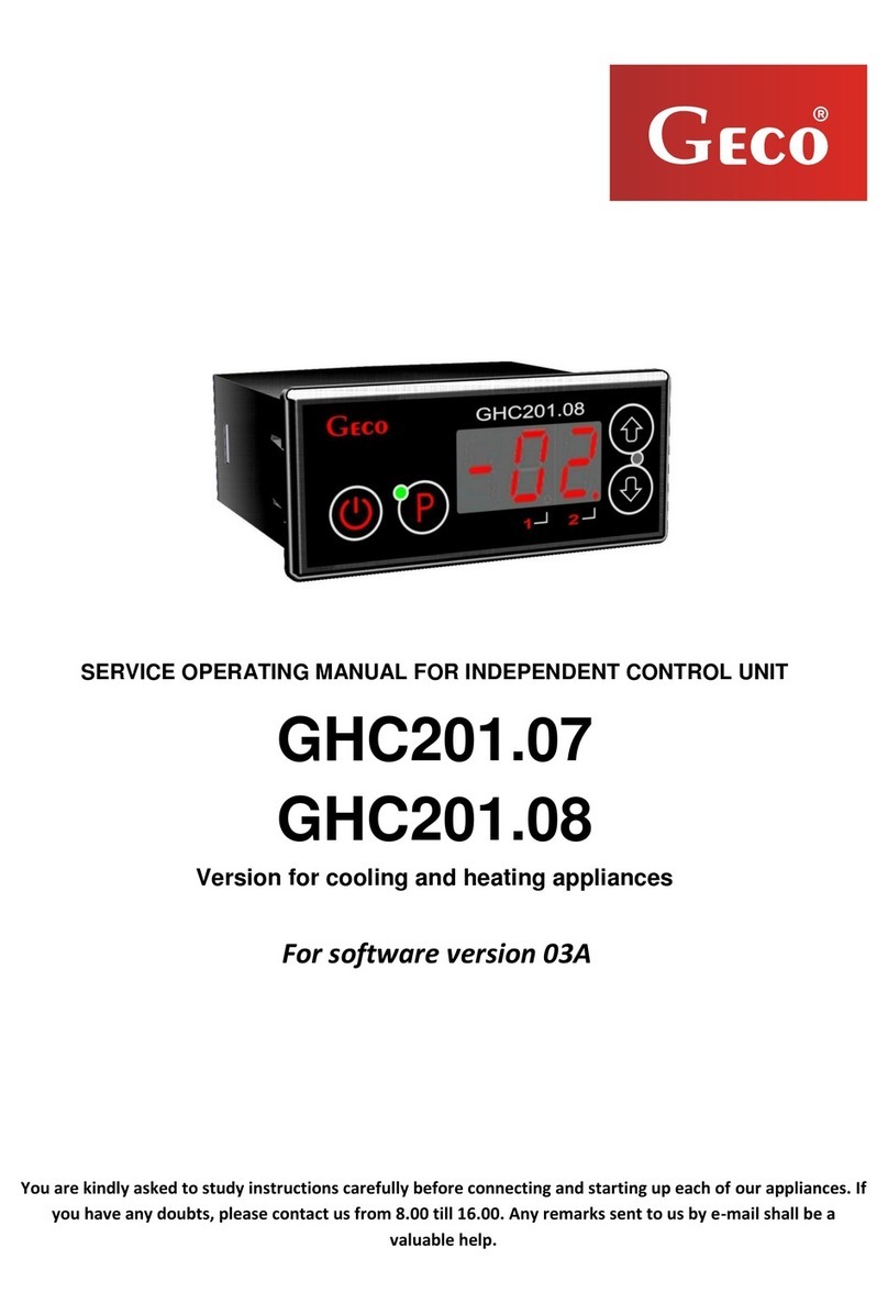
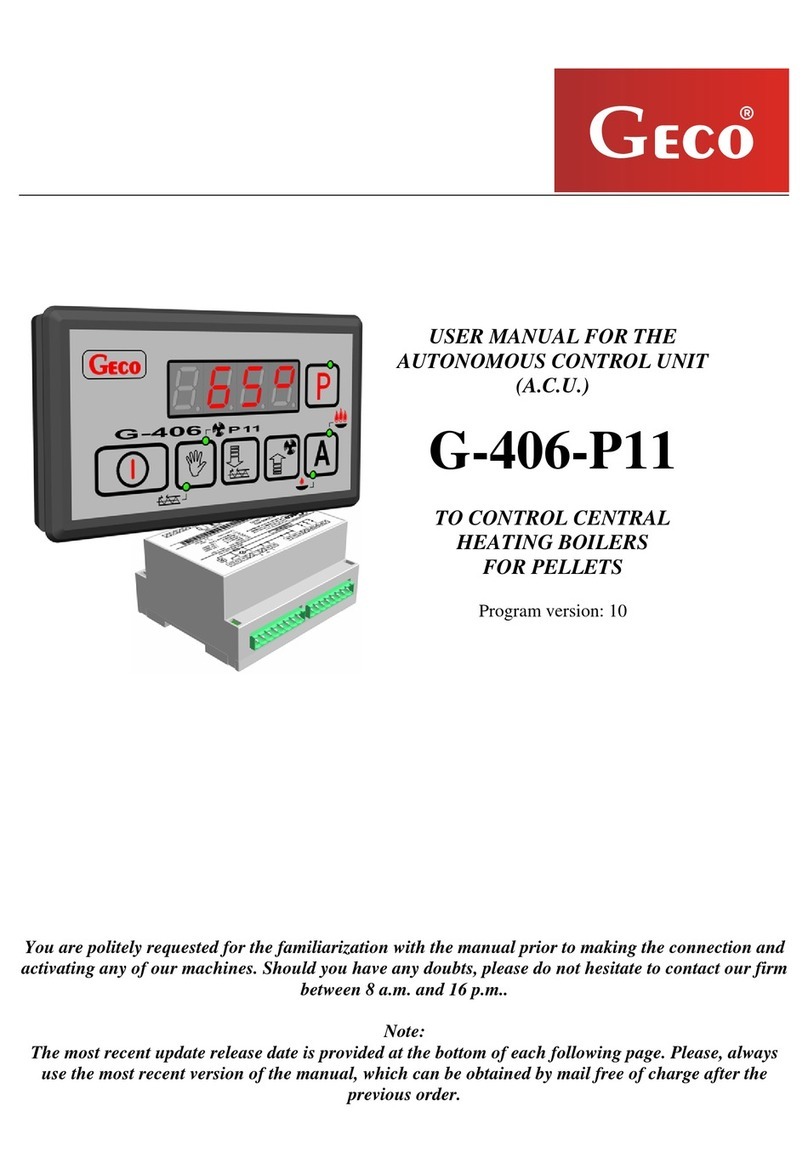
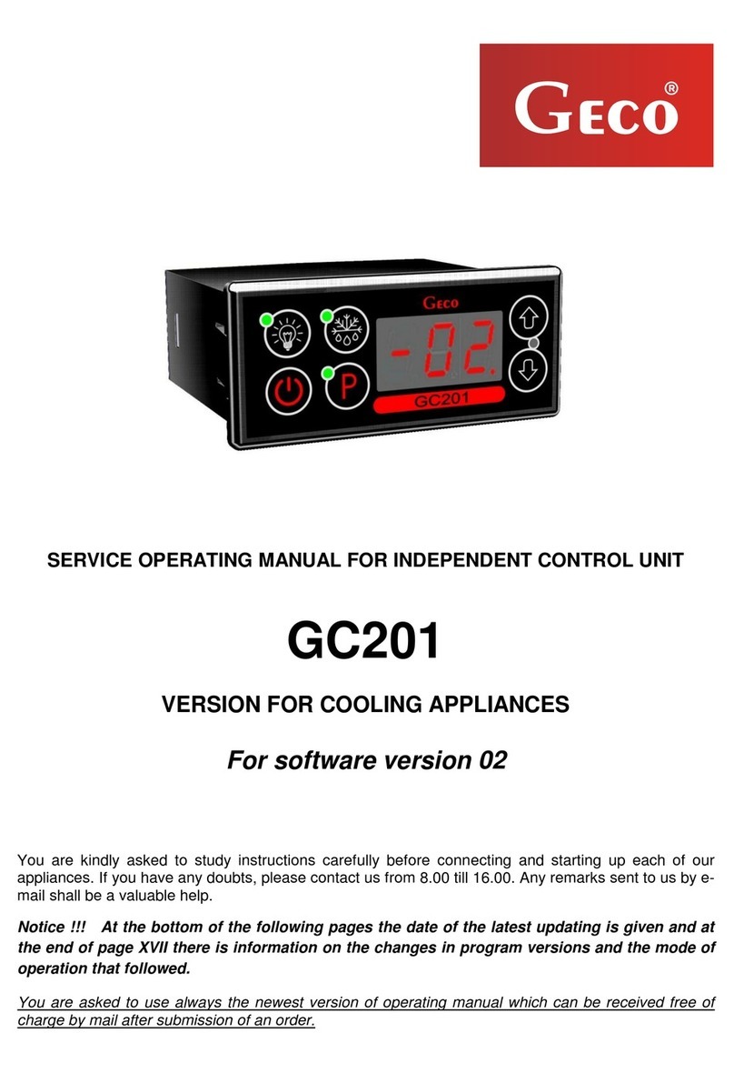
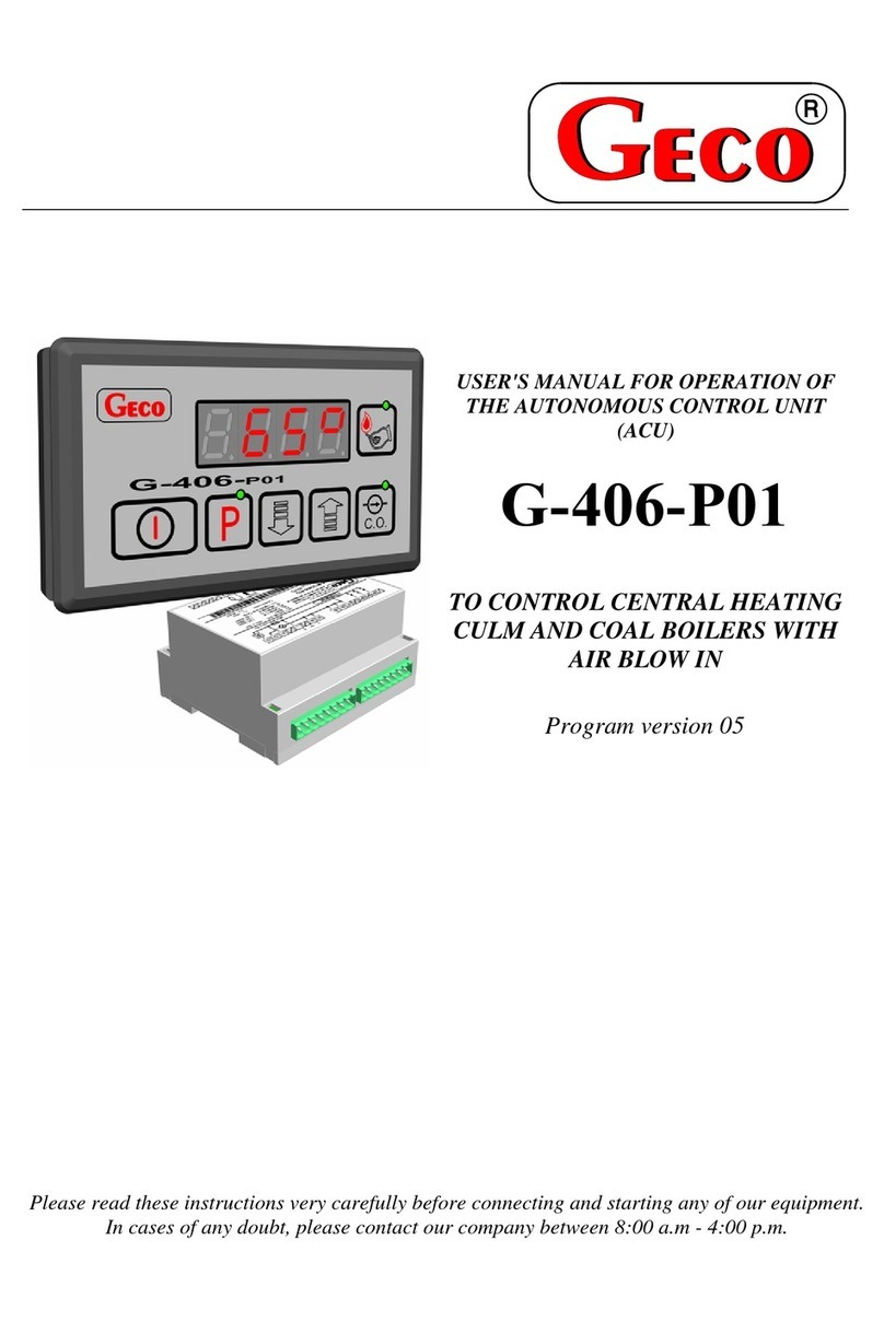
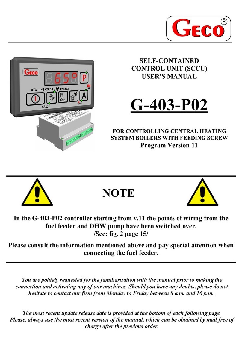
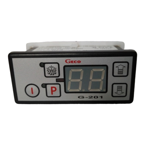
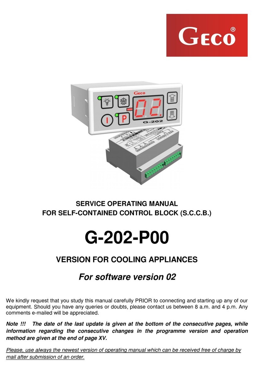
Geco G-207-P00 Series Operating instructions

P.P.U.H. "Geco" Sp. z o.o.
30-134 Krakow, ul. Zarzecze 112A
tel. +48 (12) 6369811,6361290
fax. +48 (12) 6362002
e-mail:
http://www.geco.pl
SERVICE & OPERATING INSTRUCTION
FOR AUTONOMOUS CONTROL UNIT (ACU)
G-207-P00…
VERSION FOR REFRIGERATING SYSTEMS
For program version 02
Please read these instructions very carefully before connecting and starting any of our
equipment.
In case of any doubt, please contact our company between 8:00 a.m - 4:00 p.m.
Any comments sent by e-mail will be of valuable help to us.

SERVICE MANUAL FOR MANUFACTURERS ACU TYPE G-207-P00 page 2
PPUH "GECO" - G-207-P00 program version 02 PRINTED 05-11-03
Content:
1. GENERAL..............................................................................................................................3
2. METHOD OF MARKING AND TECHNICAL DATA ..............................................................3
3. METHOD OF ORDERING .....................................................................................................4
4. DELIVERY, INSTALLATION AND HOOKUP........................................................................4
5. THE PRINCIPLE FOR INSTALLATION OF SENSORS, TYPES OF PROTECTIVE
CASES..........................................................................................................................................5
6. METHOD OF OPERATION ...................................................................................................6
8. PROGRAMMING THE SYSTEM PARAMETERS ...............................................................10
9. OPERATION OF G-207 - FOR THE USER .........................................................................13
10. TROUBLESHOOTING .....................................................................................................14
11. RETURNING THE UNIT FOR REPAIRING......................................................................16
12. BLOCK DIAGRAM, DEVICE CONNECTION INTO THE ACTUATOR............................17
13. METHOD OF INSTALLATION OF THE RIBBON CONNECTING THE PANEL AND THE
ACTUATOR................................................................................................................................17
14. BLOCK DIAGRAM FOR THE EXTENSION VERSION OF THE ACTUATOR ................18

SERVICE MANUAL FOR MANUFACTURERS ACU TYPE G-207-P00 page 3
PPUH "GECO" - G-207-P00 program version 02 PRINTED 05-11-03
1. GENERAL
Autonomous Control Unit hereinafter referred to as G-207 is a state-of-the-art, convenient and easy
to use system. It's design combines microprocessor-based technology and automatic surface assembly.
Thanks to its two-part housing and innovative engineering solutions G-207 can be used with each type
of furniture and simple cooling chamber. The control panel being supplied from safe voltage (5V) can be
mounted in any place, without being necessary to cut additional holes and run many supply cables far from
the controlled equipment.
G-207 is equipped with two temperature sensors, it enables connection of the door sensor to the control
panel or the actuator – they operate then being supplied by safe voltage 5V and have five outputs enabling
direct connection of the equipment supplied with 230V with a load capacity as per table 1.
When used with refrigerating systems the G-207 stabilizes the temperature and controls automatic
defrosting mode, the time of which can be adjusted to specific ambient conditions, it also incorporates a
button for manual defrosting of the evaporator. Versions with lighting switch working independently from
the main switch are available.
These thermostats do not require any special maintenance; the console is made of special foil resistant
to high temperatures and most chemical agents. Do not use sharp objects for cleaning it, you only need to
wipe the front panel with a damp cloth from time to time.
2. METHOD OF MARKING AND TECHNICAL DATA
Model symbol: G- 2 07 –P 00K X X – M 1XXXX X
Item: 1 2 3 4 5 6 7 8 9 10 11
1- Thermostat "Geco".
2- For refrigerating applications.
3- Type of enclosure: 07 –minipanel, 5-relay base unit
4- Start of coding related to the panel (keypad).
5- Program version 00 – universal,.
6- Way of setting the temperature: Ê- keypad.
7- Presence of the light button: L – light button present, 0 – no button.
8- Buzzer: B – buzzer present, 0 – no buzzer .
9- Start of coding related to actuator.
10- What relays are installed. Detailed description is given below.
11- Door sensor: D – mechanical or magnetic door sensor, Y - optical door sensor, 0 – the door
sensor cannot be connected.
Additional information on relay coding.
Digits indicate relay presence, 0- no relay:
1 – compressor relay - required
2 – light relay
3 - fan relay
4 - heater / valve relay
5 - second compressor relay
The simplest thermostats are equipped with:
• 10005 - compressor
• 12005 - compressor and light
And most advanced with:
• 10345 – compressor, fan, heater.
• 12345 - compressor, light,fan, heater.

SERVICE MANUAL FOR MANUFACTURERS ACU TYPE G-207-P00 page 4
PPUH "GECO" - G-207-P00 program version 02 PRINTED 05-11-03
Other examples
• 10305 – compressor and fan
• 10045 – compressor and heater
• 12305 – compressor, light,fan
• 12045 – compressor, light,heater
Operating voltage - 230V +10% -15%
Ambient temperature - from +5°C to +40°C
Moisture - from 20% to 80% RH
Protection degree - IP65 from the front side of the control panel
Table 1: Marking of relays and output load-carrying capacity
OUTPUT RELAY RECOMMENDED MAXIMUM CONTINUOUS LOAD
P1 – Compressor 30A 8A 2HP 1500W
P2 – Light 16A 4A - 750W
P3 – Fan 16A 4A 1HP 750W
P4 – Heater 16A 8A - 1500W
P5 – Compressor 30A 8A 2HP 1500W
Note !!!
• The currents specified in table are the currents drawn by individual
units during normal operation and take into account start-up currents
of these units !!!
• Total current drawn at the same time by the units must not exceed 10A!!!
3. METHOD OF ORDERING
When placing your order please specify the following:
1. Controller type: e.g. G-207-P00-KLB-M12345D
2. Length of the ribbon connecting the actuator and the keypad panel.
3. Length of the temperature sensors.
4. Length of the door sensor cable – if it is to be hooked up to the control panel (keypad)
5. Additionally, you can also order non-contact door sensors:
• magnetic sensor, with a range of 1-2 cm.
• optical sensor, with a range of 1-2 cm.
4. DELIVERY, INSTALLATION AND HOOKUP
1. In the appropriate place in the unit cut a hole of 20x30mm in size, however if masking frame of the
panel is not used the size of the hole should be 58x109mm.
2. Mount the actuator on the rail and latch it. For store equipment the ACU actuator MUST be fixed
to the floor!!!
3. Any metal elements, through which the G-207 or its cables are run should be ground or protected
otherwise. Fitting G-207 to enable direct action of water on it (e.g. water condensating on the
bottom cover of the shop window), touching the outlet pipe from the evaporator etc. and changing

SERVICE MANUAL FOR MANUFACTURERS ACU TYPE G-207-P00 page 5
PPUH "GECO" - G-207-P00 program version 02 PRINTED 05-11-03
considerably its temperature in relation to the ambient temperature (e.g. fitting in the immediate
proximity of the compressor and its accessories, cooled and heated elements) is not allowed.
4. Cut the ribbon connecting the panel with the actuator into the desired length plus 2-3cm. Then, after
running it through all penetrations, cut it once more by cutting its ends at right-angle and clip the
plugs on it so that the end of the ribbon is hidden to approx. 0.5mm. The ribbon must be introduced
perpendicular to the plug and clipped so as to make its twisting or non-parallel layout impossible.
Connecting the ribbon to the connectors see figure at the end of the instructions.
5. After fastening the G-207, connect the power cables according to the description provided on the
actuator enclosure. Depending on the G-207 version some outputs may not be used - on the
description label they will not be described and the type symbol in the corresponding places will
contain zeroes - do not connect any conductors to these outputs!!!
6. Make sure to connect the jumper supplying P5 relay – see label on the actuator enclosure. If the
jumper is not connected there will be no power at the P5 output.
7. Any cable surplus should be cut down or winded up and clamped using special plastic bands. The
cables must be firmly secured on its entire length and must not get in contact with the compressor
and its equipment.
8. After connecting the unit to the power source there can be voltage across the lighting cable
regardless of switching on or off the unit with the button , therefore the starter or the
fluorescent lamp should be replaced only with the power cord disconnected from the plug!!!
THE SAME APPLIES WHEN CARRYING OUT ANY OTHER REPAIRS!!!
8. If you use heaters, their power must be rated so that in case of G-207 or plug failure and being
switched on permanently there will be no risk of fire or damage to the equipment. If high power
heaters are used it is absolutely necessary to install a safety thermostat on the evaporator, the
principle of operation of this thermostat should be different e.g. mechanical.
5. THE PRINCIPLE FOR INSTALLATION OF SENSORS, TYPES OF PROTECTIVE
CASES
1.
For each type of the manufactured equipment a place for securing the chamber and evaporator sensors
and ACU settings should be determined experimentally. Absolutely do not change the fastening
location nor the way the sensors are secured nor modify ACU settings without prior carrying out new
tests relating to temperature stabilization and equipment defrosting cycle !!!
2. Fastening of the chamber sensor must be done in such a way so that it does not get in contact with food
products and is not exposed to damage when cleaning the equipment. The sensor can be fixed using a
special plastic bracket. This solution causes fast (on/off time delays see VI p.7 and 8) response of the
sensor and the entire thermostat to the change in the air temperature in the unit. When desired or
necessary to slow down and "smooth" the time of sensor response to the temperature changes we
recommend to fix it to the metal part of the unit.
3. Fasten the evaporator sensor in the way to ensure maximum and good contact with the evaporator
lamella and in place where ice remains for the longest time during defrosting. Its fastening should
prevent it from being pushed out by the growing ice. The sensors, wherever possible, should be fixed
vertically so that the cable exits from the bottom of the sensor.
4. Sensor cables can be shortened or extended in any way, however with respect to the following rules:
- do not cut the sensor cable at a section smaller than 0.5 m. from the case
- it is not recommended to extend the sensor cable to more than 20 m.
- THE SENSOR CABLES CAN BE CONNECTED TO THE TERMINALS OF THE ACTUATOR
SENSORS IN ANY WAY!!!
(in the same way as you connect the plug to the ~230V outlet)
- for cable extension we recommend using OMY 2x0.5 mm type conductor

SERVICE MANUAL FOR MANUFACTURERS ACU TYPE G-207-P00 page 6
PPUH "GECO" - G-207-P00 program version 02 PRINTED 05-11-03
- connect the extended cables with great care, by soldering each pair of cores and put thermally
shrinkable jackets on them. Then apply waterproof silicone on the joint and clamp one more
thermally shrinkable jacket on it.
- whiten the ends of the conductors connected to S.B.R. with tin
6. METHOD OF OPERATION
A - General
1. After connecting the unit to the power source a 3-second start-up procedure will be performed, during
which two dots will appear on the display for 1 second, following by the number of the controller
program version for the next second and then two dots again. At this time no controlled unit is
switched on.
2. After completing the start-up procedure as per section 1 two horizontal bars will appear in the central
panels of the display indicating "energized" state – provided that the unit has not been energized
before!!! The unit is started up after pressing the button . A temperature value of the chamber
sensor appears on the display.
3. After pressing and holding for 0,5 sec. the display will start blinking and showing temperature of
the evaporator, after elapse of subsequent 5 secs G-207 will automatically return to chamber
temperature reading. Note!!! This function is also active during defrosting, when
"dF" is indicated on the display. The temperature from the chamber sensor can be also seen by pressing
for 0,5 sec., the display will start showing (without blinking) the chamber temperature, after elapse
of subsequent 5 secs G-207 will automatically return to display "dF".
4. Switching on of the compressor is indicated by small red LED (dot) lighting in the right bottom corner
of the display indicating the temperature. This makes it easier to check possible system failure.
5. If the compressor is to be started then compressor P5 is switched on and then after 6 seconds
compressor P1. The same happens when turning off the units, P5 is turned off first and then P1 after 6
seconds.
6. When the compressor should start, but it will not because of tripping one of the safety devices (see
point 7), the dot indicating compressor operation will be blinking. After the time preset from the safety
devices elapses the dot will light continuously and the compressor will be started.
7. The delay in starting the compressor after reaching its starting temperature (user-preset temperature
minus lower hysteresis limit) is 30 secs. If during that time the temperature drops the 30 second limit
condition will be checked again. This is to protect the compressor from being unnecessarily turned on
such as when inserting the product, draughts, etc.
8. Each time the preset temperature is reached (user-preset temperature plus upper hysteresis limit) and
after each power voltage failure or voltage drop below 175V, G-207 will prevent the compressor from
being restarted for the time set by parameter ‘c2’. However, if ‘c2’=0min, after power loss safety mode
will last for 60 secs.
9. After starting the unit by pressing the compressor will be started after 5-second delay. Please note
that this cancels the power loss safety mode as per point 7 - this also concerns the time determined by
parameter 'c2' after prior shutting down the compressor. This way it is possible to faster check
functioning of the compressor.
10. The controller has been equipped with alarms indicating the sensor failure. The controller will behave
differently depending which sensor is defective.
• Failure of the chamber temperature sensor will result in displaying A1 symbol. The controller will
start the compressor in the time cycle (the so called "clock control") according to the times set in
parameters 'c8' and 'c9'. Defrosting will work normally.
• Sensor failure evaporator will display the alarm A2. Manual and automatic defrosting is
inhibited!!! The only possible way of defrosting the unit is to turn it on using button and wait
until ice melts in natural way.

SERVICE MANUAL FOR MANUFACTURERS ACU TYPE G-207-P00 page 7
PPUH "GECO" - G-207-P00 program version 02 PRINTED 05-11-03
• If simultaneous failure of two sensors occurs the only alarm which is displayed is A1.
When the chamber sensor is repaired A2 alarm will go on.
11. If a buzzer is incorporated into the controller, see sec. II, each button pressing is signaled by the
controller with buzzer beep. If the controller is turned off (two horizontal bars on the display) the
buzzer only indicates pressing and
.
12. The lighting is turned on and off after pressing the button . This is indicated by lighting up of the
green LED by the button. If the light goes on in the result of door opening this LED will not light up.
Button works independently from the thermostat power switch - .
B - Defrosting
1. If extra defrosting is necessary due to severe operating conditions then press button . The green LED
will light continuously on the button and "dF" will appear on the display instead of temperature
measurement, now the unit will enter the defrosting cycle.
2. If defrosting starts and the evaporator temperature is higher than the one preset with parameter 'd2' then
the unit after approx. 10 seconds will enter the defrosting phase exit mode and when it is over it will
resume operation.
3. If defrosting starts and the evaporator temperature is lower than the one preset with ‘d2’ then G-207 will
start defrosting and on reaching the temperature preset with ‘d2’ it will enter
the defrosting exit procedure (this state is indicated by green LED blinking
on the button ), in version with heaters defrosting exit procedure is started, which comprises two
subsequent phases:
• dripping phase – in which compressor and evaporator fans remain turned off for the time set by 'c3'
• evaporator freezing out phase – in which only the compressor is running in order to lower the
evaporator temperature down to a temperature set by 'd5' before restarting the fans. Maximum and
non-exceeding time of freezing out regardless of reaching the temperature ‘d5’ by the evaporator is
set with ‘c4’.
4. Defrosting exit procedure ends along with the start of fans, and "dF" goes off on the display and green
LED starts blinking on the button .
5. If the fans are not present or not connected to S.B.R. the system will operate as if they were installed.
6. Defrosting will end when the evaporator temperature reaches the value preset
with ‘d2’ or when the time preset with ‘c1’ elapses.
7. When "dF" goes off and defrosting is over the display will show the temperature memorized just before
the start of defrosting for the time preset under 'c7' – this is to avoid possible complaints due to ''rapid
temperature fluctuations within the unit''.
8. The system behaves in the same way as with manual and automatic defrosting.
C – Principle of operation of the door sensor
1. If the door is opened the fan will be immediately stopped and in G-207
depending on the ‘r7’ settings the light may go on. A temperature is shown on the display.
2. After 30 secs elapses, if the door is closed "dr" symbol will be shown continuously on the display. In
the controllers equipped with a buzzer a short beep will be heard, repeated every 30 seconds.
3. If the door remains open after the time set by ‘r8’ elapses the alarm is activated, which is indicated by
the blinking display showing "dr" and in buzzer version - by beep. At this moment the compressor is
turned off.
4. If R8 = 0, immediately on opening the door alarm is activated.
5. Pressing any button will mute the alarm. Closing doors deactivates the alarm and the operation is
resumed.

SERVICE MANUAL FOR MANUFACTURERS ACU TYPE G-207-P00 page 8
PPUH "GECO" - G-207-P00 program version 02 PRINTED 05-11-03
6. The controller allows connecting both mechanical door sensor jumpered when the door is being
opened (R6=01), as well as mechanical or magnetic sensor, opened when the door is being opened
(R6=02).
HYSTERESIS
When programming the parameters 'd0' and 'd1' (minimum and maximum temperature, which can be preset
by the user) please remember that hysteresis value 'd3' additionally 'pulls' the temperature down and up
from the user-preset temperature.
This is particularly important in case of "positive" units, which should always operate at a temperature
above 0ºC.
As the Manufacturer of the refrigerating system, in this case the refrigerated counter (positive temperature)
we expect from the unit to allow operation within temperature limits not to exceed the following values:
Turning off min: 2ººC. Turning on max: 10ººC
Symmetrical hysteresis for even values 'd3' Symmetrical hysteresis for odd values 'd3'
Example 1.
Now, let's set the hysteresis ‘d3’ to 2ºC
For the above mentioned setting of the hysteresis
you should set the parameter: ‘d0’ to 3ºC a‘d1’
to 9ºC
Example 3.
Now, let's set the hysteresis ‘d3’ to 3ºC
For the above mentioned setting of the hysteresis
you should set the parameter: ‘d0’ to 3ºC a‘d1’ to
8ºC
Example 2.
Now, let's set the hysteresis ‘d3’ to 4ºC
For the above mentioned setting of the hysteresis
you should set the parameter: ‘d0’ to 4ºC and
‘d1’ to 8ºC
Example 4.
Now, let's set the hysteresis ‘d3’ to 5ºC
For the above mentioned setting of the hysteresis
you should set the parameter: ‘d0’ to 4ºC and
‘d1’ to 7ºC
Start temp.
User-preset temp.
‘
d3
’
Stop temp.
½
‘d3’+0.5ºC
½
‘
d3
’-
½
‘
d3
’
½
‘d3’
Fig. 1 Hysteresis description.

SERVICE MANUAL FOR MANUFACTURERS ACU TYPE G-207-P00 page 9
PPUH "GECO" - G-207-P00 program version 02 PRINTED 05-11-03
7. START DIAGRAMS FOR INDIVIDUAL COMPONENTS OF THE UNIT
The bold line denotes start, and broken line stop of particular units. Defrosting exit
consists of two phases - see Chapter Vsec.3.
The field "Standstill" means shutdown, and "Operation" starting the compressor as the result of
exceeding the preset temperature, naturally taking into account the value of preset hysteresis ‘d3’. The
heater on Fig. 1 is designed for heating up the tray and/or the hose draining water from the evaporator. The
heater on Diagram 4 is designed only for heating up the hose draining water from the evaporator.
ERRONEOUS SETUP OF THE PARAMETERS WILL RESULT IN UNIT MALFUNCTIONING!!!
ªFirst 6 diagrams refers to setting the ‘r0’ = 00 parameter - During defrosting the fan starts similar to
program version 01.
1. Defrosting by compressor standstill 'r1'=01, fans are running only with the compressor 'r2'=00
t=0 (c3 & c4 n o m eanin g)
C O M PR E SS O R
TRAY HEATER
FA N
Stan dstill O peration D E FRO S TIN G D E FR O ST IN G E X IT O peration Standstill
2. Defrosting by heater ‘r1’=02, fans are running only with the compressor ‘r2’=00
t=c3 t=c4
C O M PR ESSO R
H E A T E R
FA N
Stan dstill O peration D E FRO S TIN G D E FR O ST IN G E X IT O peration Standstill
3. Defrosting using hot steam ‘r1’=03, fans are running only with the compressor ‘r2’=00
t=c3 t=c4
C O M PR ESSO R
V A LV E
FA N
Stan dstill O p eration D E F RO ST IN G D E F RO S T IN G E X IT O p eration Stan dstill
4. Defrosting using hot steam ‘r1’=03, fans are running all the time after turning on the unit ‘r2’=01
t=c3 t=c4
C O M PR ESSO R
V A LV E
FA N
Stan dstill O p eration D E FR O ST IN G D E F RO ST IN G E X IT O peration Stan dstill
5. Defrosting by compressor standstill ‘r1’=01, fans are running all the time after turning on the unit ‘r2’=01
t=0 (c3 & c4 no m eaning)
C O M PR ESSO R
DRAIN HEATER
FA N
Stan dstill O peration D E FRO ST IN G D E FRO ST IN G E X IT O peration Stan dstill
6. Defrosting by heater ‘r1’=02, fans are running all the time after turning on the unit ‘r2’=01
t=c3 t=c4
C O M PR ESSO R
H E A T E R
FA N
Stan dstill O p eration D E FR O ST IN G D E F RO ST IN G E X IT O peration S tandstill
Below diagrams refer to the ‘r0’=01 parameter.

SERVICE MANUAL FOR MANUFACTURERS ACU TYPE G-207-P00 page 10
PPUH "GECO" - G-207-P00 program version 02 PRINTED 05-11-03
7. Defrosting by heater ‘r1’=02, fans are running only with the compressor ‘r2’=00, the fan is turned on
during defrosting ‘r0’=01
t=c3 t=c4
C O M PR ES S O R
H E A T E R
FA N
Standstill O peration D E FR O ST IN G D E FR O ST IN G E X IT O peration Standstill
8. Defrosting using hot steam ‘r1’=03, fans are running all the time after turning on the unit ‘r2’=01, , the
fan is turned on during defrosting ‘r0’=01
t=c3 t=c4
C O M PR ES S O R
V A L V E
FA N
Standstill O peration D E FR O ST IN G D E FR O ST IN G E X IT O peration Standstill
9. Defrosting using hot steam ‘r1’=03, fans are running only with the compressor ‘r2’=00, , the fan is
turned on during defrosting ‘r0’=01
t=c3 t=c4
C O M PR ES S O R
V A L V E
FA N
Standstill O peration D E FR O ST IN G D E FR O ST IN G E X IT O peration Standstill
10. Defrosting by heater ‘r1’=02, fans are running all the time after turning on the unit ‘r2’=01, , the fan is
turned on during defrosting ‘r0’=01
t=c3 t=c4
C O M PR ES S O R
H E A T E R
FA N
Standstill O peration D E FR O ST IN G D E FR O ST IN G E X IT O peration Standstill
8. PROGRAMMING THE SYSTEM PARAMETERS
After starting up and checking if the unit is working correctly (factory preset standard settings) G-207
system parameters can now be entered.
For this purpose turn off the unit using the button . Then press button and
and while holding them press .All three buttons must be kept pressed down at the same time for 3
secs. Releasing any of the buttons at this time quits the programming mode. After this operation the LEDs
should start blinking on buttons and and 'c0' symbol will appear on the display for one second.
Now the last programmed value for this parameter will appear. Now using enter required settings,
pressing the button for longer time makes fast "scrolling" of the indications. Then press button , to
accept the entered value and proceed to enter the next parameter.
It is possible to enter the settings partially, if you do not want to change the particular setting press
and G207 will move to the next parameter.
Note !!!
Access to the part or even all parameters entered from the keyboard can be inhibited by the refrigerating
system Manufacturer using the computer programmer.
In this case when attempting to modify the settings of the inhibited parameter ‘bL’ will appear on the
display for approx. 1 sec.

SERVICE MANUAL FOR MANUFACTURERS ACU TYPE G-207-P00 page 11
PPUH "GECO" - G-207-P00 program version 02 PRINTED 05-11-03
Remarks on ACU programming.
1. IT IS THE RESPONSIBILITY OF THE MANUFACTURER OF THE REFRIGERATING UNIT
AND THE SERVICE ENGINEER TO ENTER NEW SETTINGS REQUIRED FOR NORMAL
FUNCTIONING OF THE UNIT!!!
2. Do the programming carefully, preferably writing down earlier the values of the particular parameters
on a sheet of paper. Remember that any error made when programming some parameters will have very
serious consequences including damage of the product and the refrigerating unit.
3. Having programmed and started the unit check it for proper operation and recheck if the settings of the
system parameters are correct.
4. Transfer of the Service Instructions or any information regarding the mode of programming the ACU
system parameters to the end user is absolutely not allowed. The end user should receive only and
exclusively a copy of the section IX of these instructions.
Table 2: Parameter designations
Para
mete
r
Description Min Max Increm
ent
Factory
preset
c0 How often should defrosting be started Note!!! If this parameter is
set to "0" defrosting will not be started in automatic, but only in
manual mode!!! If this parameter is set to "-01" defrosting will not
be started neither in automatic, or manual mode!!!
0
-01
24 1h 6h
c1 Maximum defrosting time if the evaporator does not reach the
preset temperature (parameter d2) Note!!! If this parameter is set
to "-01" there will be no time limitation
10
-01
99 min min
c2 Minimum standstill of the compressor 0 15 1min 3min
c3 Evaporator dripping time 0 15 1min 2min
c4 Time of freezing out of the evaporator, after which the fans are
started whether the evaporator reaches the preset temperature set
by 'd5' or not
0 25 1min 10min
c5 Maximum operation time of the compressor
0 – means no test (disabling this parameter)
0 99 1min 40min
c6 Standstill of the compressor after safety system trip set by 'c5' 0 99 1min 10min
c7 The time for which the temperature measured immediately before
the start of defrosting will be shown after the end of defrosting
(parameter 'c4').
0 60 1min 5min
c8 Time of operation of the compressor with faulty control sensor 1 99 1min 25min
c9 Standstill of the compressor with the faulty control sensor 1 60 1min 5min
d0 Min. temperature to be set by the client -40 20 1°C 1°C
d1 Max. temperature to be set by the client d0+1 40 1°C 10°C
d2 Evaporator temperature at which defrosting will be stopped 0 40 1°C 5°C
d3 Hysteresis value 1 10 1°C 2°C
d4 Rescaling value of the chamber sensor in relation to actually
measured temperature
-10 10 1°C 0°C
d5 Evaporator temperature, at which fans begin operation after
finishing the defrosting process
-30 10 1°C -5°C
d6 Evaporator temperature above which the fan is always turned off –
this parameter is not working during defrosting.
Setting the parametr for +40°C turns off this control.
-40 40 1°C 40°C

SERVICE MANUAL FOR MANUFACTURERS ACU TYPE G-207-P00 page 12
PPUH "GECO" - G-207-P00 program version 02 PRINTED 05-11-03
r0 Method of the fan operation during defrosting.
00-clasical using GECO algorithm
01-always turned on during defrosting
02-always turned off during defrosting
00 02 1 00
r1 Specyfing the evaporator defrosting method, parameter set to:
01 – defrosting by compressor standstill
02 – defrosting by heater
03 – defrosting using hot steam valve (reversed circulation)
01 03 1 02
r2 Specifying the evaporator fan operation mode, parameter set to:
00 – fans running only with the compressor
01 – fans running all the time after turning on the power
NOTE!!! This parameter has no effect on the cycle and evaporator
defrosting mode
00 01 1 01
r3 Specifying the temperature control mode, parameter set to:
00 – Normal control operation
01 – temperature is controlled according to the measurement from
the evaporator sensor, preset temperature and parameters D0, D1, D2
and D3 refer to evaporator sensor, measurement from the chamber
sensor is displayed.
00 01 1 00
r5 Defrosting start conditions when starting the unit.
00 – starting the operation without defrosting
01 – if during defrosting power loss is encountered then defrosting
will be started
02 – defrosting each time the unit is turned on.
00 02 1 00
r6 Door sensor option.
00 – no door sensor
01 – there is a door sensor jumpered when the door is opened
02 – there is a door sensor opened when the door is opened
00 02 1 01
r7 Mode of turning on the lighting
01 – light control only by the door sensor
02 – light control only by the key
03 – light control by the door sensor and the key
01 03 1 03
r8 Time from door opening to alarm activation.
30 seconds after door opening "dr" symbol is displayed. In the
controllers equipped with a buzzer a short beep will be heard,
repeated every 30 seconds.
Once R8 time has elapsed the alarm is activated, which is signalized
by the blinking display showing "dr" symbol and with buzzer
version - you will hear a beep and the compressor will be turned off.
0 – means immediate alarm activation
0 20 1min 1min
r9 Area where the door sensor should be hooked up:
01 – sensor hooked up to the module with relays
00 – sensor hooked up to the control module – Note! in this case you
should order a special cable with a plug!!!
00 01 1 01

SERVICE MANUAL FOR MANUFACTURERS ACU TYPE G-207-P00 page 13
PPUH "GECO" - G-207-P00 program version 02 PRINTED 05-11-03
9. OPERATION OF G-207 - FOR THE USER
1. After connecting the unit to the power source, two dots will appear on the display for 1 second,
following by the number of the controller program version and then dots again for the next second.
Then two horizontal bars will appear on the central panels of the display indicating the "power-on"
state. The unit is started up after pressing the button . A temperature value of the chamber sensor
appears on the display.
2. Setting up the stabilized temperature in the glass case.
• To change the settings, press the button . The green indicator will light on the button and the
value of the last programmed temperature is shown on the display.
• The temperature is set using the buttons . Longer pressing of the button will result in fast
"scrolling" of the indications.
• After the desired temperature is set, press again button . After this operation the green indicator
on the button will go off and G-207 will quit the programming mode and start new program
execution.
• If button is not pressed, G-207 will automatically quit the programming mode after about 5
seconds since last use of the button. The temperature value will not be saved in this case.
3.
The lighting is turned on and off after pressing the button , the green LED is lit if the lighting is on.
The light switch works independent from the main switch .
IMPORTANT !!!
If additional defrosting is necessary, due to severe operating conditions, press the button . The
green LED will light up on the button, and "dF" will appear on the display instead of the temperature
measurement and the unit will enter the defrosting cycle.
Defrosting will end automatically after the preset time elapses or on reaching the factory preset
temperature.
Attempting to repair the unit, will void the guarantee and may lead to electric shock and burn by
hot steam. Therefore all repairs should be performed by the trained and qualified service
personnel !!!

SERVICE MANUAL FOR MANUFACTURERS ACU TYPE G-207-P00 page 14
PPUH "GECO" - G-207-P00 program version 02 PRINTED 05-11-03
10. TROUBLESHOOTING
Failure symptoms Check
1. The display is off
even if G-207 is
connected to the
power supply
Check:
- if 220V is present across the power supply terminals L and N
- correct connection of the actuator to the control panel
- remove and reinsert the ribbon sockets
- connect another ribbon
2. The compressor
will not start despite
its power-on
signaling
- red LED
Check:
- 220V voltage presence on terminals K and N - If present, then check
the compressor
- if not, then check correct connection of the actuator with the control
panel
- check the jumper feeding the relay P5
- connect another ribbon
3. Heater
defrosting will not
start
Check:
- presence of 220V across the terminals according to the description
found on the upper panel of the actuator
- if present then check the heater
- if not, then check correct connection of the actuator with the control
panel
- connect another ribbon
4. Fluorescent lamp
will not light up
Check:
- presence of 230V across the terminals according to the description
found on the upper panel of the actuator
- if present, then check a/ starter b/ fluorescent lamp c/ gland
- if not, then check correct connection of the actuator with the control
panel
- connect another ribbon
5. Wrong
temperature
indications
Check:
- connections of the sensors to the connectors
- value of the parameter ‘d4’
- correct fastening of the sensor
- condition of the sensor cable – the cable can not show any damages
- carefully the appearance of the external surface of the sensor case
for any signs of mechanical damages.
6. The desired
temperature cannot
be set
Check:
value of parameters ‘d0’ and ‘d1’ (d0<d1)
7. Blinking of dots
on the display,
cannot be turned
off
Check:
- power supply voltage value
- condition of the power supply connectors
- tightening of the power supply connectors
- correct connection of the actuator to the control panel
- connect another ribbon

SERVICE MANUAL FOR MANUFACTURERS ACU TYPE G-207-P00 page 15
PPUH "GECO" - G-207-P00 program version 02 PRINTED 05-11-03
8.
‘Abnormal’,
‘strange’
behavior of
the unit.
Check:
- if 230V is present across the power supply terminals L and N
- condition of the power supply connectors
- grounding of the refrigerating unit
- condition of the electrical installation and number of the units connected
to one phase
- if you have the type of thermostat (label with output description) designed
for your unit
- if the control panel, actuator or the ribbon plugs have been exposed to
water or any other liquid
- if the control panel, actuator or ribbon plugs are exposed to moisture or
rapid temperature fluctuations
- correct connection of the actuator to the control panel
- connect another ribbon
9. Problems
with defrosting
the unit
Check:
- value of the parameter ‘d2’ and ‘c0’, ‘c1’
- value of the parameter ‘c1’. This is the maximum unit defrosting time,
whether the evaporator has reached the programmed temperature of the
end of defrosting, or not (parameter ‘d2’). If this time is too short complete
defrosting of the unit will not be possible
- correct fastening of the sensor to the evaporator lamella.
IT MUST BE FIXED SECURELY AND ADHERE CLOSELY TO THE
LAMELLA!!!
- if the evaporator sensor is fixed in place, where the ice remains for the
longest time, if not, check the temperature on the sensor at the moment,
when the last ice lumps fall off the evaporator. THIS IS THE
TEMPERATURE WHICH SHOULD BE ENTERED AS PARAMETER ‘d2’
10. The unit
does not
reach the
preset
temperature
and does not
‘refrigerate’
Check:
- the temperature programmed by the user
- value of the individual parameters, and in particular 'c2', 'c5', 'd0', 'd1'
- point 9 - Problems with unit defrosting. If unit defrosting is not complete,
the unit will not be able to reach the programmed temperature !!!
- the way and place of securing the chamber sensor
- if any side panes have been fitted in the rack or sliding panes in the glass
case
- IF THE UNIT IS LEFT IN THE DRAFT OR IN THE SUN !!!
- if there are no fans or air conditioning units installed on the ceiling or
nearby
- if condenser is clean
- temperature in the store (each manufacturer specifies max. working
temperature of the unit)
- gas volume, fans, evaporator heater, hose draining water from the
evaporator
11. improper
operation of
the door
sensor
Check:
- value of the parameter ‘r6’ and ‘r7’, ‘r9’
- correct connection of the sensor
- if the sensor is connected to the actuator, check correct connection of
the actuator to the control panel
- connect another ribbon

SERVICE MANUAL FOR MANUFACTURERS ACU TYPE G-207-P00 page 16
PPUH "GECO" - G-207-P00 program version 02 PRINTED 05-11-03
11. RETURNING THE UNIT FOR REPAIRING
In case of failure and returning ACU for repair, it is absolutely required to completely
fill in the replacement application form provided at the end of these instructions. We
suggest making a Xerox copy of the form rather than cutting it.
PPUH ‘GECO’ reserves the right to refuse acceptance of the unit for
repair free of charge if the form has not been enclosed or submitted
incomplete and seal break attempt has been proved !!!
P.P.U.H. ‘Geco’ Sp. z o.o. assumes no liability for any loss
or damage resulting from offering by the refrigerating unit manufacturer or his
service personnel information to the end user on the procedure of modifying the
ACU system data, wrong or unprofessional installation and for any loss
resulting from faulty operation of the unit.

SERVICE MANUAL FOR MANUFACTURERS ACU TYPE G-207-P00 page 17
PPUH "GECO" - G-207-P00 program version 02 PRINTED 05-11-03
12. BLOCK DIAGRAM, DEVICE CONNECTION INTO THE ACTUATOR
Fig. 2. Block diagram .
13. METHOD OF INSTALLATION OF THE RIBBON CONNECTING THE PANEL AND THE
ACTUATOR
Fig. 3 Front panel and modules connection.

SERVICE MANUAL FOR MANUFACTURERS ACU TYPE G-207-P00 page 18
PPUH "GECO" - G-207-P00 program version 02 PRINTED 05-11-03
14. BLOCK DIAGRAM FOR THE EXTENSION VERSION OF THE ACTUATOR
Fig. 4 Block diagram for the extension version of the actuator.

SERVICE MANUAL FOR MANUFACTURERS ACU TYPE G-207-P00 page 19
PPUH "GECO" - G-207-P00 program version 02 PRINTED 05-11-03

SERVICE MANUAL FOR MANUFACTURERS ACU TYPE G-207-P00 page 20
PPUH "GECO" - G-207-P00 program version 02 PRINTED 05-11-03
P.P.U.H. "Geco" spółka z o.o.
30-134 Kraków ul. Zarzecze 112 A
tel. 012 6369811, 6361290
fax. 012 6362002
http://www.geco.pl
This manual suits for next models
2
Table of contents
Other Geco Control Unit manuals
Popular Control Unit manuals by other brands

Emerson
Emerson Anderson Greenwood 93 Series Installation and maintenance instructions

Dorot
Dorot S100 quick start guide

Allen-Bradley
Allen-Bradley ArmorBlock 1732E-8IOLM12R Wiring diagrams

Kontron
Kontron CP-RIO3-04S user guide

Cycle Stop Valves
Cycle Stop Valves CSV1A installation instructions

Watson McDaniel
Watson McDaniel HSP Series Installation & maintenance manual