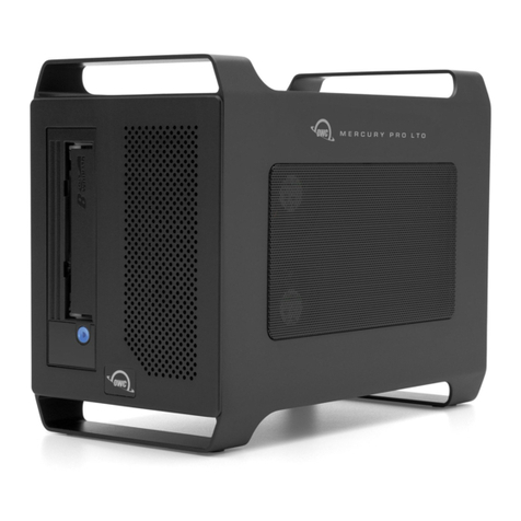
Netberg Aeon J460 M2 JBOD User manual

Netberg Aeon J460 M2 JBOD

Netberg Aeon J460 M2 JBOD

iii
Table of Contents
1. Netberg Aeon J460 M2 JBOD ............................................................................................ 1
1.1. Conventions ............................................................................................................ 2
1.2. Safety Information ................................................................................................... 3
1.2.1. Important Safety Instructions ......................................................................... 3
1.3. Disclaimer ............................................................................................................... 4
2. About JBOD ...................................................................................................................... 5
2.1. Introduction ............................................................................................................. 6
2.2. System Features ..................................................................................................... 7
2.3. Package content ..................................................................................................... 9
2.4. A Tour of the System ............................................................................................ 10
2.4.1. System ....................................................................................................... 10
2.4.2. System Front View ..................................................................................... 11
2.4.3. Control Panel ............................................................................................. 12
2.4.4. System Rear View ...................................................................................... 14
2.4.5. SIM Module ................................................................................................ 14
2.4.6. LED Status Definitions ................................................................................ 15
2.4.7. HDD LEDs ................................................................................................. 17
2.4.8. ISIM LEDs .................................................................................................. 18
3. Install Hardware ............................................................................................................... 19
3.1. Safety Measures ................................................................................................... 20
3.2. Hard Disk Drive Module ......................................................................................... 21
3.2.1. Removing a HDD Module ........................................................................... 21
3.2.2. Installing a HDD Module ............................................................................. 23
3.3. Hard Disk Drive Assembly ..................................................................................... 25
3.3.1. Removing a HDD Assembly ........................................................................ 25
3.3.2. Installing a HDD Assembly .......................................................................... 25
3.4. Power Supply Unit ................................................................................................. 27
3.4.1. Removing a PSU ........................................................................................ 27
3.4.2. Installing a PSU ......................................................................................... 27
3.5. Fan Modules ......................................................................................................... 29
3.5.1. Removing a Fan Module ............................................................................. 29
3.5.2. Installing a Fan Module ............................................................................... 29
3.6. SAS Interface Modules .......................................................................................... 31
3.6.1. Removing a SIM ......................................................................................... 31
3.6.2. Installing a SIM .......................................................................................... 31
3.7. Internal SAS Interface Modules .............................................................................. 33
3.7.1. Removing an ISIM ...................................................................................... 33
3.7.2. Installing an ISIM ........................................................................................ 33
3.8. Rail Kit Assembly .................................................................................................. 35
3.8.1. Installing the Rack Brackets ........................................................................ 35
3.8.2. Installing a Cable Management Arm ............................................................ 37
3.9. Cable Routing ....................................................................................................... 40
3.9.1. One-Server Topology .................................................................................. 40
3.9.2. Two-Server Topology (Zone II) .................................................................... 41
3.9.3. Four-Server Topology (Zone III) .................................................................. 42
4. Server Safety Information ................................................................................................. 43
4.1. Safety Warnings and Cautions ............................................................................... 44
4.2. Intended Application Uses ..................................................................................... 46
4.3. Site Selection ........................................................................................................ 47

Netberg Aeon J460 M2 JBOD
iv
4.4. Equipment Handling Practices ................................................................................ 48
4.5. Power and Electrical Warnings ............................................................................... 49
4.6. Power Cord Warnings ........................................................................................... 50
4.7. System Access Warnings ...................................................................................... 51
4.8. Rack Mount Warnings ........................................................................................... 52
4.9. Electrostatic Discharge (ESD) ................................................................................ 53
4.10. Other Hazards ..................................................................................................... 54
4.11. Cooling and Airflow ............................................................................................. 55
4.12. Laser Peripherals or Devices ............................................................................... 56
5. Regulatory and Compliance Information ............................................................................ 57
5.1. Electromagnetic Compatibility Notices .................................................................... 59
5.1.1. FCC Verification Statement (USA) ............................................................... 59
5.1.2. Europe (CE Declaration of Conformity) ........................................................ 59
5.1.3. VCCI (Japan) ............................................................................................. 60
5.1.4. KCC (Korea) .............................................................................................. 60
5.1.5. Regulated Specified Components ................................................................ 60
5.1.6. Restriction of Hazardous Substances (RoHS) Compliance ............................ 61
5.1.7. End of Life / Product Recycling ................................................................... 61

v
List of Figures
2.1. System Component Overview ........................................................................................ 10
2.2. Component Placement Schema ..................................................................................... 11
2.3. System Front View ........................................................................................................ 11
2.4. Control Panel ................................................................................................................ 12
2.5. System Rear View ......................................................................................................... 14
2.6. SIM Module .................................................................................................................. 14
2.7. HDD Leds ..................................................................................................................... 17
2.8. SIM Module .................................................................................................................. 18
3.1. 2.5" HDD module removal ............................................................................................. 21
3.2. 3.5" HDD module removal ............................................................................................. 22
3.3. Disconnecting Interposer Card ....................................................................................... 22
3.4. Installing Interposer Card ............................................................................................... 23
3.5. 2.5” HDD module installation ......................................................................................... 24
3.6. 3.5” HDD module installation ......................................................................................... 24
3.7. Removing HDD Assembly .............................................................................................. 25
3.8. Installing HDD Assembly ............................................................................................... 26
3.9. Removing PSU ............................................................................................................. 27
3.10. Installing PSU ............................................................................................................. 28
3.11. Removing Fan Module ................................................................................................. 29
3.12. Installing Fan Module .................................................................................................. 30
3.13. Removing SIM ............................................................................................................. 31
3.14. Installing SIM .............................................................................................................. 32
3.15. Removing ISIM ............................................................................................................ 33
3.16. Installing ISIM ............................................................................................................. 34
3.17. Disassembling the Rails ............................................................................................... 35
3.18. Installing an Inner Rail ................................................................................................. 36
3.19. Installing Outer Rail ..................................................................................................... 36
3.20. Aligning Rails .............................................................................................................. 37
3.21. Installing Cable Management Arm ................................................................................ 38
3.22. Straps ......................................................................................................................... 38
3.23. Installing Cable Management Arm ................................................................................ 39
3.24. One-Server Topology_1 ............................................................................................... 40
3.25. One-Server Topology_2 ............................................................................................... 41
3.26. Four-Server Topology .................................................................................................. 41
3.27. Four-Server Topology .................................................................................................. 42

vi
List of Tables
2.1. Netberg Aeon J460 M2 JBOD ......................................................................................... 7
2.2. System Components Overview ...................................................................................... 10
2.3. System Front View ........................................................................................................ 11
2.4. Control Panel ................................................................................................................ 12
2.5. System Rear View ......................................................................................................... 14
2.6. SIM Module Features .................................................................................................... 14
2.7. LED Status ................................................................................................................... 15
2.8. HDD LEDs .................................................................................................................... 17
2.9. ISIM LEDs .................................................................................................................... 18
5.1. Product Regulatory Compliance Markings ....................................................................... 57

1
Chapter 1. Netberg Aeon J460 M2
JBOD

Netberg Aeon J460 M2 JBOD
2
1.1. Conventions
Several different typographic conventions are used throughout this manual. Refer to the following
examples for common usage.
Bold type face denotes menu items, buttons and application names.
Italic type face denotes references to other sections, and the names of the folders,menus, pro-
grams, and files.
<Enter> type face denotes keyboard keys.
Warning information appears before the text it references and should not be ignored
as the content may prevent damage to the device.
CAUTIONS APPEAR BEFORE THE TEXT IT REFERENCES, SIMILAR TO NOTES
AND WARNINGS. CAUTIONS, HOWEVER, APPEAR IN CAPITAL LETTERS AND
CONTAIN VITAL HEALTH AND SAFETY INFORMATION.
Indicates information that is important to know for the proper completion of a proce-
dure, choice of an option,or completing a task.
Highlights general or useful information and tips.

Netberg Aeon J460 M2 JBOD
3
1.2. Safety Information
1.2.1. Important Safety Instructions
Read all caution and safety statements in this document before performing any of the instructions.
Warnings
Heed safety instructions: Before working with the server, whether using this manual or any other
resource as a reference, pay close attention to the safety instructions. Adhere to the assembly in-
structions in this manual to ensure and maintain compliance with existing product certifications and
approvals. Use only the described, regulated components specified in this manual. Use of other
products / components will void the UL listing and other regulatory approvals of the product and
will most likely result in non-compliance with product regulations in the region(s) in which the prod-
uct is sold.
System power on/off: The power button DOES NOT turn off the system AC power. To remove
power from system,you must unplug the AC power cord from the wall outlet. Make sure the AC
power cord is unplugged before opening the chassis, adding, or removing any components.
Hazardous conditions, devices and cables: Hazardous electrical conditions may be present on
power, telephone, and communication cables. Turn off the server and disconnect the power cord,
telecommunications systems, networks, and modems attached to the server before opening it.
Otherwise, personal injury or equipment damage can result.
Electrostatic discharge (ESD) and ESD protection: ESD can damage drives, boards, and other
parts. We recommend that you perform all procedures in this chapter only at an ESD workstation.
If one is not available, provide some ESD protection by wearing an antistatic wrist strap attached
to chassis ground any unpainted metal surface on the server when handling parts.
ESD and handling boards: Always handle boards carefully. They can be extremely sensitive to
electrostatic discharge (ESD). Hold boards only by their edges. After removing a board from its
protective wrapper or from the server, place the board component side up on a grounded, static
free surface. Use a conductive foam pad if available but not the board wrapper. Do not slide board
over any surface.

Netberg Aeon J460 M2 JBOD
4
1.3. Disclaimer
The informa tion in this document is subject to change without notice. The manufacturer makes no
representations or warranties with respect to the contents hereof and specifically disclaims any im-
plied warranties of merchantability or fitness for any particular purpose. Furthermore, the manufac-
turer reserves the right to revise this publication and to make changes from time to time in the con-
tent hereof without obligation of the manufacturer to notify any person of such revision or changes.
All the illustrations in this technical guide are for reference only and are subject to change without
prior notice.

5
Chapter 2. About JBOD

About JBOD
6
2.1. Introduction
This manual is written for system technicians who are responsible for troubleshooting, upgrading,
and repairing the JBOD chassis. This document provides an overview of the hardware features of
the system, management information, and instructions on how to add and replace components of
the JBOD.

About JBOD
7
2.2. System Features
Table2.1.Netberg Aeon J460 M2 JBOD
Specification:
Enclosure Form Factor 4U Rack mount chassis
HDD Support 6Gb/s 3.5” or 2.5” SAS or SATA hot-swap HDD
(up to 60)
Host Interface 6Gb/s mini-SAS port per SIM (x4)
Supported HBA Card
Hot-Swap and Redundancy
Controller Module
- Hot-swappable SAS Interface Module (SIM)
(x2)
- Hot-swappable Internal SAS Interface Module
(ISIM) (x4)
Disk Drives Hot-swap HDD (x60 bays)
Cooling Fans
- Total 7+1 redundant main fans
- One built-in fan in each power supply unit
Power Supply 1400W redundant power supplies, 240 VAC
Monitoring and Notification
LED Indicator
- Power LED
- System ID/ Status LED
- HDD Active and ID/ Status LED
- Internal SAS Interface Module Status LED
Firmware Management SCSI enclosure service (SES-2)
OS Support
- Windows
- Linux
System Dimensions
Dimensions (H x W x D)
Without Cable Management Arms:
- 175.3 mm x 447.0 mm x 909.0 mm
- 6.9” x 17.6” x 35.8”
With Cable Management Arms:
- 175.3 mm x 447.0 mm x 1103.1 mm
- 6.9” x 17.6” x 43.4”
Weight Without HDDs:

About JBOD
8
Specification:
- 37.0 kg
- 81 lbs
With HDDs fully loaded:
- 85 kg
- 187 lbs
Environmental
Operating temperature 5°C to 40°C (41°F to 104°F)
Humidity 50% to 93% relative humidity
Altitude 33°C / 3200m
Operational Vibration 5 Hz ~ 350 Hz, 0.26 Grms
Regulations Safety Regulations

About JBOD
9
2.3. Package content
• 1 x JBOD storage system
• 2 x power cord
• 1 x mini-USB cable
• Rail kit
• Cable management arm

About JBOD
10
2.4. A Tour of the System
These sections show the major components found on the
Netberg Aeon J460 M2 JBOD system.
2.4.1. System
Component Overview
Figure2.1.System Component Overview
5
4
3
2
1
1
2
3
4
Table2.2.System Components Overview
№ Component
1 Internal SAS interface module (x4)
2 Fan module (x4)
3 HDD (x60)
4 Control panel

About JBOD
11
Component Placement
Figure2.2.Component Placement Schema
HDD
0
HDD
1
HDD
2
HDD
3
HDD
4
HDD
5
HDD
12
HDD
13
HDD
14
HDD
15
HDD
16
HDD
17
HDD
6
HDD
7
HDD
8
HDD
9
HDD
10
HDD
11
HDD
18
HDD
19
HDD
20
HDD
21
HDD
22
HDD
23
HDD
24
HDD
25
HDD
26
HDD
27
HDD
28
HDD
29
HDD
30
HDD
31
HDD
32
HDD
33
HDD
34
HDD
35
HDD
36
HDD
37
HDD
38
HDD
39
HDD
40
HDD
41
HDD
42
HDD
43
HDD
44
HDD
45
HDD
46
HDD
47
HDD
48
HDD
49
HDD
50
HDD
51
HDD
52
HDD
53
HDD
54
HDD
55
HDD
56
HDD
57
HDD
59
HDD
59
PSU
SIM
SIM
PSU
FAN
FAN
FAN
FAN
1
5
HDD Array 1 HDD Array 2 HDD Array 3 HDD Array 4 HDD Array 5
5
4
3
2
1
ISIM 0 ISIM 1 ISIM 2 ISIM 3
2.4.2. System Front View
Figure2.3.System Front View
5
4
3
2
1
2 1
Table2.3.System Front View
№ Item
1 Control panel
2 Front grill

About JBOD
12
2.4.3. Control Panel
Figure2.4.Control Panel
5
4
3
2
1
1
2
3
4
5
6
7
8
9
10
11
12
See the HDD array definition in section “Component Placement”.
Table2.4.Control Panel
№ Icon Item
1 Power button with LED
2 System status LED
3 Fan status LED
4 PSU status LED
5 SIM status LED

About JBOD
13
№ Icon Item
6 ISIM status LED
7 ID button with LED
8
1
HDD array 1 LED
9
2
HDD array 2 LED
10
3
HDD array 3 LED
11
4
HDD array 4 LED
12
5
HDD array 5 LED

About JBOD
14
2.4.4. System Rear View
Figure2.5.System Rear View
SERVICE
6Gb/s S
A
S
CASCADEIN
CASCADEOUT
HOST 0 HOST 1
HOST 2
HOST 3
SERVICE
6Gb/s S
A
S
CASCADEIN
CASCADEOUT
HOST 0
HOST 1
HOST 2
HOST 3
1
2
3
Table2.5.System Rear View
№ Item
1 Fan module (x4)
2 SIM module (x2)
3 Power supply unit (x2)
2.4.5. SIM Module
Figure2.6.SIM Module
SERVICE
6Gb/s S
A
S
CASCADEIN
CASCADEOUT
HOST 0
HOST 1
HOST 2 HOST 3
0 1 2 3
1
2
3
4
5
6
7
Table2.6.SIM Module Features
№ Icon Item
1 MiniSAS port (x4)
Table of contents
Popular Storage manuals by other brands
Exabyte
Exabyte Mammoth Installation and operation
Fujitsu Siemens Computers
Fujitsu Siemens Computers PRIMERGY SX30 operating manual
Synology
Synology DiskStation DS415+ Quick installation guide
UPOWER Ecoline
UPOWER Ecoline UE-WM Series user manual

Memorex
Memorex traveldrive quick start guide

Samsung
Samsung MZ-5PA064B user manual

