Lipco GSG-NV Series User manual

Operating Manual
Cross-flow fan unit with trailer tank type GSG-NV
(one row / two rows)
LIPCO GmbH
Am Fuchsgraben 5b
D-77880 Sasbach
Tel.
+49 (0) 7841 6068-0
Fax
+49 (0) 7841 6068-10
email
Internet
http://www.lipco.com/
GSG-NV2 with 1000 l trailer tank
GSG-NV2 with 1500 l trailer tank
This manual applies to one row and 2 rows type

Operating Manual
Cross-flow fan unit type GSG-NV1 / 2
2 - 64
010980-26-E BA GSG-NV1_2 / 23.03.2012
Introduction
Dear Customer:
Thank you for choosing a LIPCO Cross-flow fan unit with tank trailer
type GSG-NV1 / 2. We are confident that you will be satisfied with
our product.
In order to achieve maximum performance from your new LIPCO
Cross-flow fan unit with tank trailer type GSG-NV1 / 2 over an ex-
tended period, please follow the instructions in this operating manual
closely. This will help you to prevent any damage and also to prevent
accidents that could result from failure to comply with the manual
and for which LIPCO can assume no liability.
This operating manual is an essential component of the machine and
therefore must always be included when the machine is sold, also if
it is sold to third parties.
By carefully storing the operating manual in a safe place, both you
and the operator will have a comprehensive reference work at hand.
Note:
The illustrations, descriptions and data contained in this operating
manual are not binding. LIPCO reserves the right to make changes
at any time, without prior notice.

Operating Manual
Cross-flow fan unit type GSG-NV1 / 2
3 - 64
010980-26-E BA GSG-NV1_2 / 23.03.2012
Table of contents Page
1. Authorized use ................................................................................... 5
2. Warnings on the machine................................................................... 6
3. General safety regulations.................................................................. 7
4. Safety information for handling plant protection agents...................... 8
5. Accident prevention............................................................................ 9
6. Construction details of the GSG-NV / standard equipment .............. 10
7. Construction details of the GSG-NV / special equipment................. 11
8. Advantages of LIPCO tunnel spray technology................................ 11
9. Technical data GSG-NV................................................................... 12
10. Components of GSG-NV.................................................................. 13
10.1. Filters................................................................................................ 13
10.2. Fan width adjustement ..................................................................... 14
10.3. Tunnel height adjustment................................................................. 15
10.4. Tanks of GSG-NV............................................................................. 15
10.5. The different valves of the LIPCO GSG-NV: .................................... 17
11. Preparation....................................................................................... 20
12. Attachment to the towing vehicle...................................................... 20
13. Attachment of the universal joint shaft.............................................. 23
14. Driving on roads with the GSG-AN2................................................. 25
15. Operating the LIPCO GSG-NV......................................................... 27
15.1. Determining the amount of spray liquid needed ............................... 27
15.2. Checking the driving speed .............................................................. 27
15.3. Calculation of the driving speed ....................................................... 28
15.4. Nozzle selection and distribution quantity......................................... 29
15.5. Checking the liquid discharge........................................................... 30
15.6. Nozzle adjustment during operation................................................. 32
15.7. Spray nozzle adjustment.................................................................. 33
15.8. Recycling device............................................................................... 34
16. Setting the LIPCO GSG-NV ............................................................. 36
16.1. Calculation of the liquid discharge.................................................... 36
16.2. Calculation of the required plant protection agent/spray................... 37
16.3. Intervals for checking the dosing and distribution accuracy of the
LIPCO GSG-NV................................................................................ 38
16.4. Which plant protection agents can be used in the LIPCO GSG-NV ?...
38
17. Conducting test spraying.................................................................. 39
18. Preparation of spraying liquid........................................................... 40
19. Emptying the GSG-NV after use ...................................................... 42
20. Residual volume............................................................................... 42
21. Interruption of spraying process ....................................................... 43
22. Cleaning of the GSG-NV after use ................................................... 44
23. Maintenance..................................................................................... 47
24. Machine inspection........................................................................... 52
24.1. Pressure check................................................................................. 52
24.2. Flow rate check ................................................................................ 52

Operating Manual
Cross-flow fan unit type GSG-NV1 / 2
4 - 64
010980-26-E BA GSG-NV1_2 / 23.03.2012
25. Troubleshooting................................................................................ 53
26. Storing the machine.......................................................................... 55
27. Warranty........................................................................................... 57
28. Functional diagram GSG-NV............................................................ 58
29. Electric diagram for GSG-NV ........................................................... 59
30. Hydraulic diagram for GSG-NV ........................................................ 60
31. Notes................................................................................................ 61
32. EG Declaration of conformity............................................................ 63

Operating Manual
Cross-flow fan unit type GSG-NV1 / 2
5 - 64
010980-26-E BA GSG-NV1_2 / 23.03.2012
1. Authorized use
The LIPCO Cross-flow fan unit with tank trailer type GSG-NV1 / 2
with recycling technology is intended for double-sided spraying of
plant protection agents for vineyards, rose and berry plantations and
similar cultures.
LIPCO-GSGfan units are Julius-Kühn Institute Braunschweig /
Germany (JKI)- approved and registered in the list of loss-reducing
devices. For classification and authorized use please refer to actual
folder „Verlustmindernde Geräte“ (www.jki.bund.de/geraete“)
Technical modifications without any written agreement, either by
LIPCO or JKI, are not allowed. Otherwise LIPCO Cross-flow fan unit
with tank trailer type GSG-NV1 / 2 will lose its classification as loss-
reducing device.
Any other use is deemed not authorized. The manufacturer will not
be liable for damages resulting from unauthorized use; the user will
be solely responsible for all risks in this case.
Authorized use also includes compliance with the manufacturer’s
operating, maintenance and repair instructions.
The operator is responsible for compliance with applicable accident
prevention regulations, in addition to the generally recognized safety,
occupational health and traffic safety regulations.
Unauthorized modifications to the LIPCO Cross-flow fan unit with
tank trailer type GSG-NV1 / 2 will release the manufacturer from
liability for resulting damages.
Note for use on public roads
Before driving on public roads and paths, make sure that the
combination of tractor and LIPCO Cross-flow fan unit with tank
trailer type GSG-NV1 / 2 or other combined equipment complies
with the applicable traffic regulations (maximum gross weight,
maximum axle loads, lights, warning signs, etc.). It may be nec-
essary to transport the LIPCO Cross-flow fan unit with tank trailer
type GSG-NV1 / 2 on a flatbed truck.
Note
The LIPCO Cross-flow fan unit with tank trailer type GSG-NV1 /
2 is also referred to in this operating manual only as
LIPCO GSG-NV.

Operating Manual
Cross-flow fan unit type GSG-NV1 / 2
6 - 64
010980-26-E BA GSG-NV1_2 / 23.03.2012
2. Warnings on the machine
Before operating the machine, always read the oper-
ating manual and comply with all safety instructions!
Always shut off the motor and remove the ignition
key when performing maintenance or repairs!
Danger of parts being catapulted while drive unit is in
operation –maintain safety clearance!
Operate machine only at the specified speed
(max. 540 rpm)!
Danger of poisoning –never climb into container!

Operating Manual
Cross-flow fan unit type GSG-NV1 / 2
7 - 64
010980-26-E BA GSG-NV1_2 / 23.03.2012
3. General safety regulations
The operation of mobile plant protection units is associated with cer-
tain risks. Therefore, you must comply with the following safety regu-
lations:
Before operating the machine, always read the operating manual
and comply with all safety instructions!
Never remove or modify safety devices!
Never enter the area beneath the machine for repairs or inspec-
tions unless the machine is secured!
Prior to performing maintenance or care, make sure that the
machine is switched off!
Always maintain safety clearances!
Caution! Do not enter the work area while the universal joint shat
is rotating! There is an increased risk of accident in case of con-
tact. For your safety, do not wear loose clothing or accessories
(e.g. scarves)!
The LIPCO GSG-NV may be operated, maintained and repaired
only be personnel who are specially trained and are aware of the
risks involved!
The operator is responsible for compliance with applicable acci-
dent prevention regulations, in addition to the generally recog-
nized safety, occupational health and traffic safety regulations!
The warning and information signs on the machine provide im-
portant information for safe operation; compliance with these
warnings will increase your safety!
Persons not involved must keep out of the work area of the ma-
chine.
Keep children away from the LIPCO GSG-NV and spray.
Operate machine only at the specified speed
(max. 540 rpm)!

Operating Manual
Cross-flow fan unit type GSG-NV1 / 2
8 - 64
010980-26-E BA GSG-NV1_2 / 23.03.2012
4. Safety information for handling plant protection agents
Do not use plant protection agents that tend to gum up or con-
geal –they have a negative effect on spraying.
Before applying heat (welding, soldering, etc.) in order to repair
the tunnel spray unit or attachments that come into contact with
the plant protection agent, these units must be cleaned thor-
oughly with water.
Standard safety devices may not be removed or modified.
Damaged safety devices must be replaced by new ones.
Damaged seals and shut-off devices must be replaced.
Persons who come into contact with plant protection agents or
who work with the tunnel spray unit must protect themselves with
suitable protective gear against contamination from the plant pro-
tection agents. (safety gloves, etc.)
Always comply with the regulations of the plant protection agent
manufacturer and of the trade association. AID brochure 1042
(2) provides information on the safe handling of plant protection
agents.
Relevant literature is available from:
Evaluation and information service for nutrition, agriculture and
forestry (AID), P.O. Box 20 02 53, 53173 Bonn.
AID brochure 2079 (1):
Filling plant protection agent machines: caution in taking water
from the drinking water supply and public waters.
AID brochure 1042 (2):
Caution in handling herbicides and plant protection agents.
Do not eat, drink or smoke when working with herbicides and
plant protection agents.
Wash hands and face thoroughly with soap and water after every
contact with spraying equipment or spray liquid and after com-
pletion of work.

Operating Manual
Cross-flow fan unit type GSG-NV1 / 2
9 - 64
010980-26-E BA GSG-NV1_2 / 23.03.2012
5. Accident prevention
Most accidents that occur during use, maintenance or transport
are caused by failure to comply with the simplest basic rules.
Therefore it is important that all persons involved with use of the
machine are aware of and comply with the following rules:
In order to achieve maximum performance from the LIPCO
GSG-NV it must be in proper working order. Maintenance and
repair may be performed only by trained personnel. Replace-
ment parts must fulfill the minimum technical specifications re-
quired by the manufacturer! This is ensured only by the use of
LIPCO original replacement parts!
Before each use, check the trailer hitch bolts on the three-point
mount and all nuts and bolts!
Exercise special caution when using roads or paths, e.g. for turn-
ing the entire tunnel spray unit.
Always shut off the motor and remove the ignition key when per-
forming maintenance or repairs!
During work and transport on roads do not transport objects or
persons on the machine!
Operate machine only with drive unit fully protected, i.e. univer-
sal joint shaft completely covered and additional protection on
tractor and GSG.Make sure that the universal joint shaft connec-
tions lock securely into place!
The machine should be on a level surface or a stable support
during all work on the machine!
When working on the machine in raised position, always secure
by mechanical means using suitable supports!

Operating Manual
Cross-flow fan unit type GSG-NV1 / 2
10 - 64
010980-26-E BA GSG-NV1_2 / 23.03.2012
6. Construction details of the GSG-NV / standard equipment
frame with double-coat paint RAL 6011
cross-flow fan unit width adjustment (infinitely variable / common
or single action) and drawbar adjustment with hydraulic cylinder,
both electrically controlled by control unit, including control box for
tractor cabin
hydraulic drawbar for tight turning radius and front support
adjustable axle, with mechanical clamping
2 (one row) / 4 (two rows) hydraulic driven cross-flow fans,
equipped with collecting tray and hydro injector for the leading
back of the unused liquid - minimum operating pressure 5 bar re-
quired for suction
one V4A nozzle tube each integrated in the cross-flow fans,
with 5 drip-stop rotary nozzle bodies with flat fan venturi nozzles
(AVI 80° green –or other output quantities on request) –individu-
ally adjustable
pressure filter (80 mesh), suction filter (50 mesh) and recycling
filter (50 mesh)
1000 liter tank with tank cleaning nozzle and injector agitator,
water jet mechanism integrated in filling screen
100 l fresh water tank with 3-way tap for switching for cleaning the
equipment and 15 l hand-washing container integrated in 1000 l.
tank
full electrical control: Nozzles, recycling, pressure and agitator
can be controlled via control box on tractor, manometer built into
control box
12V lighting in accordance with motor vehicle regulations
tires 10.0 / 75-15.3 tt 8 PR
160 l. pump, 16 bar
universal joint shaft

Operating Manual
Cross-flow fan unit type GSG-NV1 / 2
11 - 64
010980-26-E BA GSG-NV1_2 / 23.03.2012
7. Construction details of the GSG-NV / special equipment
The following special equipment is available:
Row width 2,40 m / 3,20 m
Width adjustment 1.30 m instead of 1.10 m (standard)
Hydraulic height adjustment 300 mm
Hydraulic adjustable axle, instead of mechanical one, stroke 300
mm, with synchronous cylinder
Hydraulic navigating drawbar
External spray agent mixer for transferring mixture to tank and
rinsing residue from the containers
Working lights between fans,
3-way tap with quick release coupler and 2.50 m hose for exter-
nal suction
Electrical monitoring unit with display (output l/min., speed and
effective output in liters)
Electrical monitoring and control unit type SPRAYDOS, with
digital display, incl. on board computer and boom section switch-
es
Other nozzles
2 agent-sprayer type BS 2
8. Advantages of LIPCO tunnel spray technology
The fan design causes a higher spray concentration and there-
fore a more intensive deposition of spray on the plants.
Negative effects of natural wind outside of the fan unit on the
spraying are kept to a minimum.
Spray that is not deposited on the plants is collected in a pan
and filtered for re-use.
The spray nozzles can be switched on and off based on the
height of the foliage wall for optimum use of spray.
Operating Manual
Cross-flow fan unit type GSG-NV1 / 2
12 - 64
010980-26-E BA GSG-NV1_2 / 23.03.2012
9. Technical data GSG-NV
GSG-NV1
1500 l
Tank
GSG-NV2
1000 l
Tank
GSG-NV2
1500 l
Tank
Weight
kg
950
980
1170
Required drive power
kW
35
35
40
Pump type
AR 160 bp
AR 160 bp
AR 160 bp
Number of fans
2
4
4
Row width
m
1.80 –
2.20 / 3.20
1.80 –
2.20 / 3.20
1.80 –
2.20 / 3.20
Width adjustment
standard
m
0,20 –
1,10
0,20 –
1,10
Required pump capacity
l / min
30
30
35
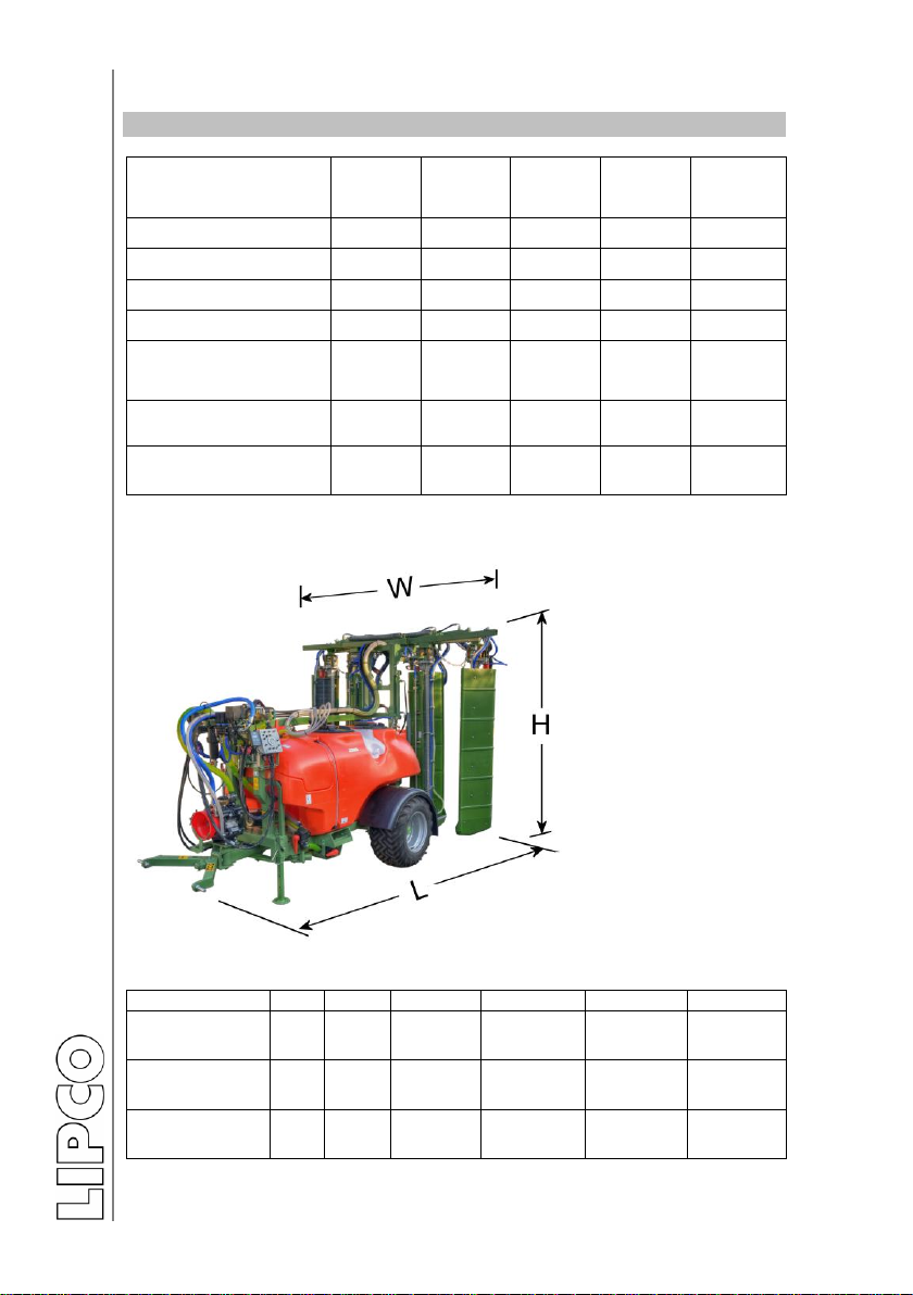
External main dimensions during use on public roads:
Picture shows GSG-NV2
type
L (m)
W (m)
H (m)
GSG NV1 –
1500 l tank
NV2
3,25
2,00
2,45
GSG NV2 –
1000 l tank
NV2
3,25
2,00
2,45
GSG NV2 –
1500 l tank
NV2
3,55
2,00
2,45
Operating Manual
Cross-flow fan unit type GSG-NV1 / 2
13 - 64
010980-26-E BA GSG-NV1_2 / 23.03.2012
10.Components of GSG-NV
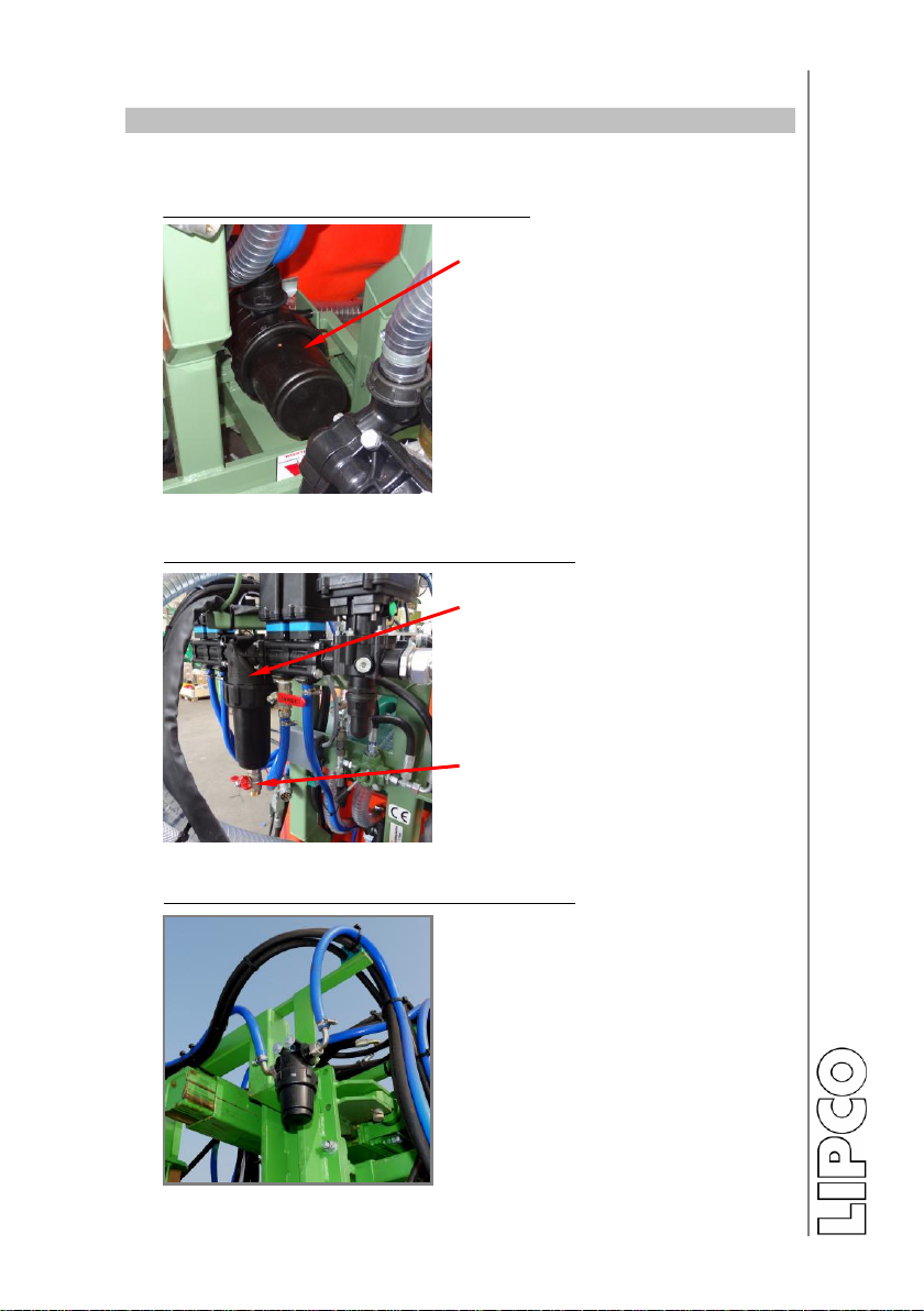
10.1. Filters
Suction filter –mesh width 0.508 mm:
The suction filter is in front of
the spray liquid tank.
The filter insert should be
checked several times daily for
dirt and cleaned, if necessary.
Fig. 1
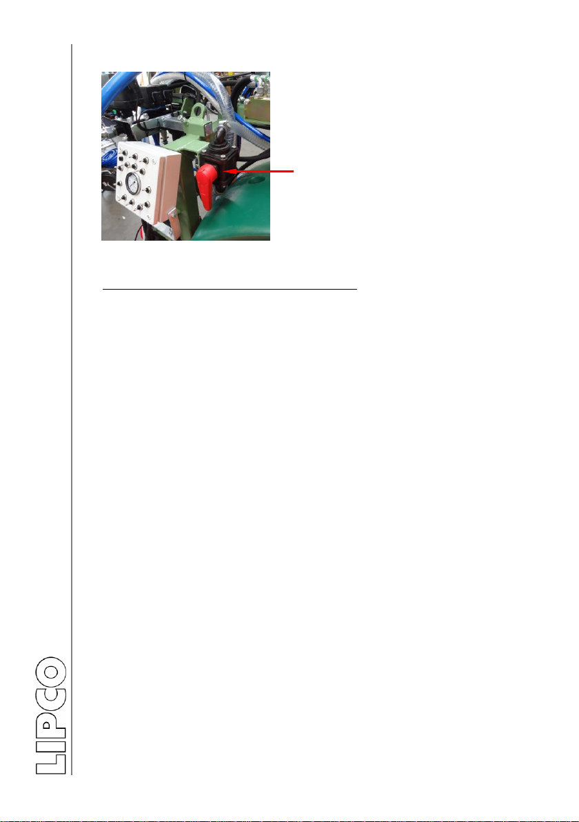
Pressure filter 1 –mesh width 0.3175 mm:
The pressure filter is located
between the shut-off motors.
The filter insert should be
check several times daily for
dirt and cleaned, if necessary.
Drain valve for draining con-
taminated spray liquid.
Fig. 2
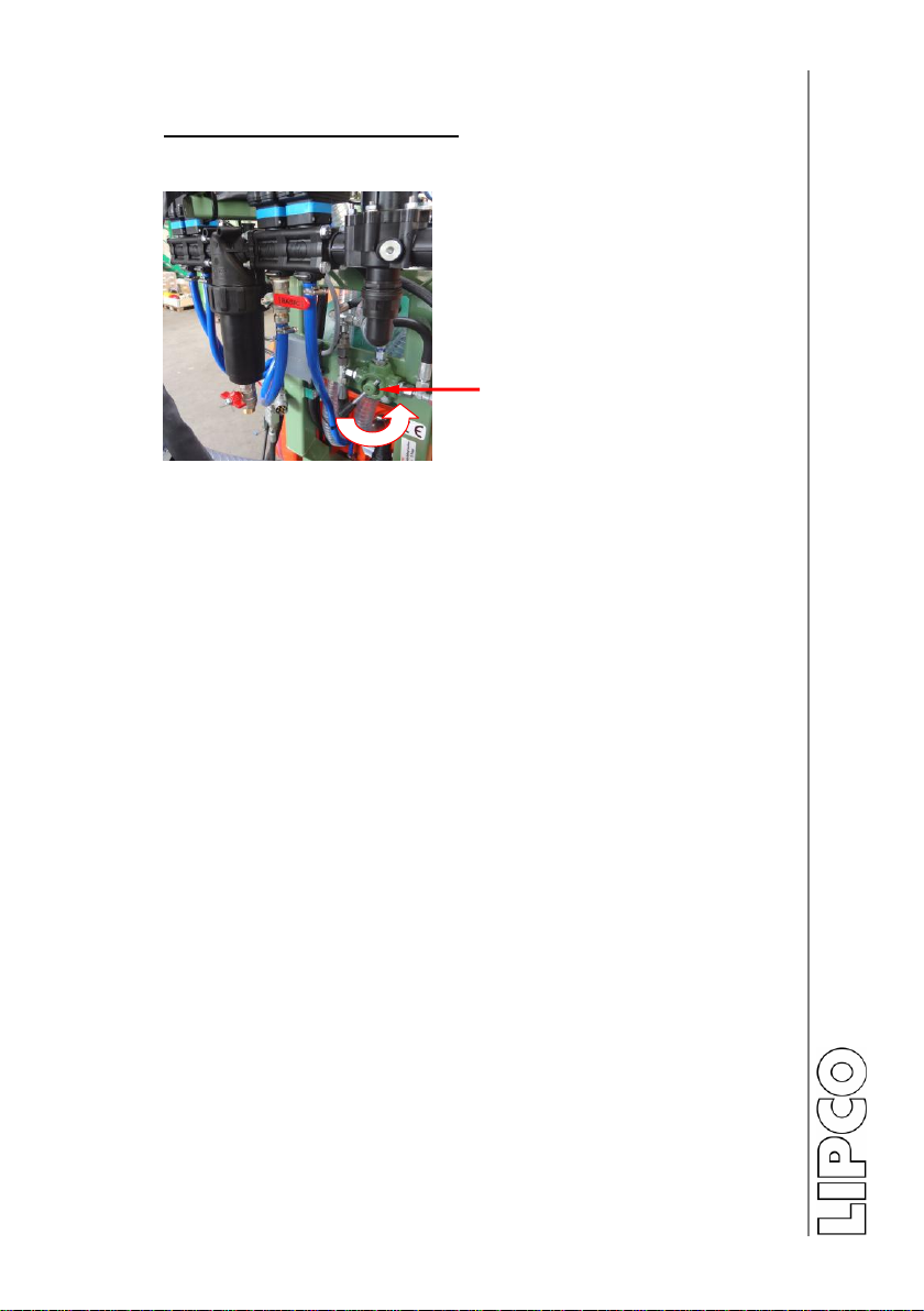
Pressure filter 2 –mesh width 0.3175 mm:
Additional pressure filters in
circuit close to spray nozzles
The filter inserts must be
checked several times daily
and cleaned, if necessary.
.
Fig. 3

Operating Manual
Cross-flow fan unit type GSG-NV1 / 2
14 - 64
010980-26-E BA GSG-NV1_2 / 23.03.2012
Recycling filter –mesh width 0.508 mm:
The recycling filter in the return
flow of the recycled spray must
be checked several times daily
and cleaned, if necessary.
Recycling filter insert
Fig. 4
10.2. Fan width adjustement
The fan width is adjusted man-
ually from the tractor via hy-
draulic, double-action control
valve.
Hydraulic cylinder for tunnel
width adjustment.
Fig. 5
Row width can be adjusted by
reallocating adequate chain.
Chain
Fig. 6

Operating Manual
Cross-flow fan unit type GSG-NV1 / 2
15 - 64
010980-26-E BA GSG-NV1_2 / 23.03.2012
10.3. Tunnel height adjustment
Hydraulic height adjustment (special edition):
Tunnel(s) can be adjusted sim-
ultaneously.
Hydraulic cylinders for height
adjustment
Fig. 6a
10.4. Tanks of GSG-NV
Spray liquid tank / fresh water tank:
Fresh water tank (green)
On back side of spray liquid
tank
Spray liquid tank (red)
Fig. 7
Caution:
Do not fill the fresh water tank with spray liquid!!
Fresh water tank for cleaning the LIPCO GSG-NV after comple-
tion of spraying.
Do not drink out of fresh water tank!!

Operating Manual
Cross-flow fan unit type GSG-NV1 / 2
16 - 64
010980-26-E BA GSG-NV1_2 / 23.03.2012
Hand washing tank
Hand washing tank (green)
on front side of spray liquid
tank
valve for hand washing
Fig. 8
Caution:
Do not fill the hand washing tank with spray liquid!!
Do not drink out of hand washing tank!!

Operating Manual
Cross-flow fan unit type GSG-NV1 / 2
17 - 64
010980-26-E BA GSG-NV1_2 / 23.03.2012
10.5. The different valves of the LIPCO GSG-NV:
2-way valve
3-way valve
Fig. 9
Function of the 3-way valve (Fig. 9)
Position: “Suction tank”
Liquid is pumped from the spray liquid tank / fresh
water tank to the nozzles in the tunnel walls.
Position: “Clean suction filter”
Spray liquid circuit is blocked, suction filter can be
removed and cleaned.
Position: “Empty tank”
Spray liquid tank can be emptied.
Place the collector beneath the valve and dispose of
the collected spray agent in accordance with JKI
BRAUNSCHWEIG (JKI) regulations.
Function of the front 2-way valve (Fig. 9)
Position: “Machine cleaning”
Pump conveys fresh water from the fresh water tank
through the spray nozzles to the injectors and via the
recycling filter back into the spray liquid tank.
Position: “Suction tank”
Pump conveys spray liquid from the spray liquid tank
to the spray nozzles.
Operating Manual
Cross-flow fan unit type GSG-NV1 / 2
18 - 64
010980-26-E BA GSG-NV1_2 / 23.03.2012
2-way valve
Fig. 10
Function of the front 2-way valve (Fig. 10)
Position: “Machine cleaning”
Pump conveys fresh water from the fresh water tank
through the spray nozzles to the injectors and via the
recycling filter back into the spray liquid tank.
Position: “Suction tank”
Pump conveys spray liquid from the spray liquid tank
to the spray nozzles.
The second 2-way valve is situated between pres-
sure regulator and pump –see also functional dia-
gram.
Note:
Both 2-way valves (Fig. 9 + Fig. 10) must always be in some po-
sition, either for spaying or for cleaning.
That means, e.g. both valves in position “suction tank” or in posi-
tion “machine cleaning”.
Operating Manual
Cross-flow fan unit type GSG-NV1 / 2
19 - 64
010980-26-E BA GSG-NV1_2 / 23.03.2012
Function of the shut-off valve :
All fans can be easily shut off /on, if necessary, with one valve
Shut-off / on valve
Fig. 10a

Operating Manual
Cross-flow fan unit type GSG-NV1 / 2
20 - 64
010980-26-E BA GSG-NV1_2 / 23.03.2012
11. Preparation
In order to ensure safety and efficiency when operating the LIPCO
GSG-NV the following tasks must be performed prior to starting
work:
Always replace or install any damaged or missing components
before operating the machine!
Check to make sure that all bolts are tightened.
Check the hydraulic lines for damage and replace, if necessary,
according to the regulations of the trade association.
Before each use, make sure that all safety devices on the tractor,
LIPCO GSG-NV and the universal joint shaft are installed and
functioning.
12. Attachment to the towing vehicle
Before operation, check the machine and the towing vehicle to
ensure that they are safe for traffic and safe for operation!
No one may enter the area between the towing vehicle and the
LIPCO GSG-NV unless the vehicle is secured against rolling by
means of the parking brake and / or wheel chocks!
Do not enter the turning and swiveling area of the machine!
When the machine is in transport position, always make sure
that the tractor’s lower links are sufficiently blocked from the side
in order to prevent the machine from swinging out to the side!
The lower links must be secured so that they do not impact the
tractor tires.
This manual suits for next models
2
Table of contents


