Samoa LARIUS GHIBLI 30:1 Operating instructions

www.larius.com
REV. 02 - 09/2020
Manuale Cod. 150088
GHIBLI
30:1/40:1
Airless pneumatic pump
for spray painting
II 2 G Ex h IIB T6 Gb
OPERATING AND MAINTENANCE MANUAL
EN

Due to a constant product improvement programme, the factory reserves the right to modify
technical details mentioned in this manual without prior notice.
This manual is to be considered as an English language translation of the original manual in Italian.
The manufacturer shall bear no responsibility for any damages or inconveniences that may arise due to
the incorrect translation of the instructions contained within the original manual in Italian.

www.larius.com
1
GHIBLI 30:1/40:1
REV.. 01 - 03/2020 - Cod. 150088
GHIBLI 30:1 / 40:1
Airless pneumatic pumps for spray painting
A
C
D
B
E
H
G
F
I
M
N
J
K
L
O
P
Q
R
S
T
U
V
W
X
Y
Z
AA
AB
WE ADVISE THE USE OF THIS EQUIPMENT ONLY BY PROFESSIONAL OPERATORS.
ONLY USE THIS MACHINE FOR USAGE SPECIFICALLY MENTIONED IN THIS MANUAL.
Thank you for choosing a LARIUS S.R.L. product.
As well as the product purchased, you will receive a range of support services
enabling you to achieve the results desired, quickly and professionally.
INDEX
WARNINGS ..................................................................................................................................................................2
WORKING PRINCIPLE .................................................................................................................................................3
TECHNICAL DATA ........................................................................................................................................................3
DESCRIPTION OF THE EQUIPMENT ..........................................................................................................................5
TRANSPORT AND UNPACKING ..................................................................................................................................7
CONDITIONS OF GUARANTEE ...................................................................................................................................8
SAFETY RULES............................................................................................................................................................8
SETTING-UP ................................................................................................................................................................9
WORKING ..................................................................................................................................................................11
CLEANING AT THE END OF THE WORK...................................................................................................................11
ROUTINE MAINTENANCE .........................................................................................................................................12
MANUAL RESET OF THE PNEUMATIC MOTOR .......................................................................................................13
DISASSEMBLY OF THE PNEUMATIC MOTOR..........................................................................................................13
DISASSEMBLY OF THE PUMPING GROUP.............................................................................................................14
PROBLEMS AND SOLUTION ....................................................................................................................................15
SPARE PARTS
COMPLETE PNEUMATIC MOTOR PUMP GHIBLI SPLIT VERSION 30:1/40:1 BASE VERSION..............................18
COMPLETE PNEUMATIC MOTOR PUMP GHIBLI SPLIT VERSION 30:1/40:1 TROLLEY AND WALL VERSION ....20
COMPLETE PUMPING PUMP GHIBLI 30:1 / 40:1 GALVANIZED AND STAINLESS STEEL VERSION .....................22
AIR REGULATION - TROLLEY AIRLESS VERSION RIF. 96250 .................................................................................25
AIR REGULATION - WALL AIRLESS VERSION RIF. 96250/1 ...................................................................................26
AIR REGULATION - TROLLEY AIR ASSISTED AIRLESS VERSION RIF. 96262........................................................27
AIR REGULATION - WALL AIR ASSISTED AIRLESS VERSION RIF. 96262/1............................................................28
COMPLETE FILTER SPLIT GHIBLI 30:1/40:1 ............................................................................................................30
PAINT SUCTION SYSTEM .........................................................................................................................................32
COMPLETE TROLLEY................................................................................................................................................33
WALL SUPPORT GHIBLI 30:1/40:1 RIF. 91200/1 ......................................................................................................34
ACCESSORIES...........................................................................................................................................................35
ATEX CERTIFICATION ................................................................................................................................................38
CERTIFICATE OF CONFORMITY ...............................................................................................................................41

www.larius.com
2
GHIBLI 30:1/40:1
REV.. 01 - 03/2020 - Cod. 150088
The table below provides the meaning of the symbols used in this manual in relation to using, earthing,
operating, maintaining, and repairing of this equipment.
WARNINGS
A
FIRE AND EXPLOSION HAZARD
To help prevent fire and explosion:
- Use equipment ONLY in well ventilated area.
- Use only grounded hoses.
must be stopped immediately.
-
regulations.
To help prevent injection, always:
If high pressure fluid pierces your skin, the injury might look like “just a cut”, but it is a serious wound!
Get immediate medical attention.

www.larius.com
3
GHIBLI 30:1/40:1
REV.. 01 - 03/2020 - Cod. 150088
B
C
Parts of the pump in contact with the material
Sealing balls: stainless steel AISI 420B
Other parts of the pump
*N.B.
WORKING PRINCIPLE
GHIBLI 30:1 and 40:1
piston.
This allows for the material to be aspirated and pushed towards
high-pressure material filter, an air supply regulator for the pump, a
The ratio 30:1 or 40:1 means that the outlet pressure of material
is 30 or 40 times higher than the pump feed air pressure.
TECHNICAL DATA
Always observe these instructions carefully
when evaluating the product compatibility and
in case of disposal of some parts of the pump no
more usable, in order to meet the environmental
regulations on recycling process.
GHIBLI 30:1 GHIBLI 40:/1
Maximum delivery 3,8 l/m 2,8 l/m
Maximum infeed air pressure 7 bar 6,5 bar
Max. working pressure 210 bar 260 bar
*Airfeed inlet 1/2” GAS (F) 1/2” GAS (F)
Material entry 3/4" GAS C (M) 3/4" GAS C (M)
Material exit 3/8" GAS C (F) 3/8" GAS C (F)
Air consumption 3 bar 400 l/m 3 bar 400 l/m
5 bar 800 l/m 5 bar 800 l/m
7 bar 850 l/m 6,5 bar 850 l/m
Sound pressure level < 80 dB (A) < 80 dB (A)
Motor diameter 180 mm (4 1/4") 180 mm (4 1/4")
Piston stroke 102 mm (4") 102 mm (4")
c.c. Cycle 60 45
N° cycles per minute 60 60
N° cycles per liter 16 22
Seals PTFE + Polietilene PTFE + Polietilene
Weight 25 kg 25 kg
Height 930 mm 930 mm
Width 450 mm 450 mm
Depth 450 mm 450 mm

www.larius.com
4
GHIBLI 30:1/40:1
REV.. 01 - 03/2020 - Cod. 150088
a
l
p
O 0,2 0,4 0,6 0,8 GPM 0
O 1 2 3 4 L/MIN.
PUMP DELIVERY
PRESSURE RELEASE MATERIAL
BAR
200
160
120
80
40
0
PSI
3200
2800
2400
2000
1600
1200
800
400
AIR CONSUMPTION
L/MIN.
1000
800
600
400
200
0
CFM
40
35
30
25
20
15
10
5
BLACK CURVE: PRESSURE RELEASE MATERIAL
GRAY CURVE: AIR CONSUMPTION
7 bar (100 psi) 5 bar (70 psi) 3 bar (40 psi)
O 0,2 0,4 0,6 0,8 GPM 0
O 1 2 3 4 L/MIN.
PUMP DELIVERY
PRESSURE RELEASE MATERIAL
BAR
250
200
150
100
50
0
PSI
4000
3500
3000
2500
2000
1500
1000
500
AIR CONSUMPTION
L/MIN.
1000
800
600
400
200
0
CFM
40
35
30
25
20
15
10
5
BLACK CURVE: PRESSURE RELEASE MATERIAL
GRAY CURVE: AIR CONSUMPTION
7 bar (100 psi) 5 bar (70 psi) 3 bar (40 psi)
The pump can operate continuously when the flow is limited to the white area.
Outside of this area, the speed must be intermittent.
The pump can operate continuously when the flow is limited to the white area.
Outside of this area, the speed must be intermittent.
GHIBLI 30:1 GHIBLI 40:1
Fig. 1C

www.larius.com
5
GHIBLI 30:1/40:1
REV.. 01 - 03/2020 - Cod. 150088
D
4
5
6
7
8
9
10
11
12
13
14
15
16
17
1
2
319
18
20
Pos. Description
1 Compressed air inlet
2 Manometer reading air pressure alim. pump
3 Feed air pressure regulator. pump
4 Trolley transport equipment
5 Valve opening and closing air alim. pump
6 Pneumatic motor pump
7 High pressure filter material outlet
8 High pressure filter out material
9 Recirculating cock
10 Recirculation pipe fitting fixing
11 Fluid recirculation pipe
Pos. Description
12 Material suction pipe
13 Material suction filter
14 Fitting pipe fitting intake
15 Material pumping group
16 Air-material flexible pipe
17 Air-mix spray technology
18 Atomizing air pressure gauge reading
19 Atomizing air pressure regulator
20 Cable grounding with gripper
21 AT250 Gun
22 L91 Gun
DESCRIPTION OF THE EQUIPMENT
Fig. 1D

www.larius.com
6
GHIBLI 30:1/40:1
REV.. 01 - 03/2020 - Cod. 150088
5
4
3
3
2
2
19
18
1
1
20
6
14
7
8
10
15
9
"Air assisted airless" version
Airless version
Fig. 2D

www.larius.com
7
GHIBLI 30:1/40:1
REV.. 01 - 03/2020 - Cod. 150088
E
AT250 gun L91 gun
21 22
16
13
12
11
TRANSPORT AND
UNPACKING
and also suitable hoisting equipment for the weight of
the installation or its parts.
been any damage due to transportation.
or anomalies must arrive timely within 8 days at least
Letter to the Shipping Agent and to LARIUS.
Fig. 3D

www.larius.com
8
GHIBLI 30:1/40:1
REV.. 01 - 03/2020 - Cod. 150088
F
G
The conditions of guarantee do not apply in the
following situations:
- improper washing and cleaning of components
causing malfunction, wear or damage to the
equipment or any of its parts;
- improper use of the equipment;
- use that does not conform with applicable
national legislation;
- incorrect or faulty installation;
-modifications,interventionsandmaintenancethat
have not been authorised by the manufacturer;
- use of non-original spare parts or parts that do
not correspond to the specific model;
- total or partial non-compliance with the
instructions provided.
CONDITIONS OF GUARANTEE
SAFETY RULES
ALL THOSE RISKS STEMMING FROM ACCIDENTS, ABOUT
THE USE OF SAFETY DEVICES FOR THEIR OWN SAFE-
TY AND ABOUT THE GENERAL RULES FOR ACCIDENT
PREVENTION IN COMPLIANCE WITH INTERNATIONAL
REGULATIONS AND WITH THE LAWS OF THE COUNTRY
WHERE THE PLANT IS USED.
COMPLY WITH THE ACCIDENT PREVENTION AND ALSO
ENVIRONMENTAL REGULATIONS IN FORCE IN THE
COUNTRY WHERE THE PLANT IS INSTALLED AND USED.
WHERE YOU ARE WORKING CREATES A POTENTIAL RISK
OF ACCIDENTS.
STANCE.
DAMAGED PARTS AND THE MACHINE CAN WORK PRO-
PERLY.
AND THE REGULATIONS IN FORCE.
EQUIPMENT OUT OF THE WORK AREA.
NEVER EXCEED THE MAXIMUM WORKING PRESSURE
INDICATED.
NEVER POINT THE SPRAY GUN AT YOURSELVES OR AT
OTHER PEOPLE. THE CONTACT WITH THE CASTING CAN
CAUSE SERIOUS INJURIES.
SEEK IMMEDIATE MEDICAL ADVICE SPECIFYING THE
TYPE OF THE PRODUCT INJECTED. NEVER UNDERVALUE
A WOUND CAUSED BY THE INJECTION OF A FLUID.
PRESSURE IN THE CIRCUIT BEFORE PERFORMING ANY
CHECK OR PART REPLACEMENT OF THE EQUIPMENT.
REGULARLY THE COMPONENTS OF THE SYSTEM.
REPLACE THE PARTS DAMAGED OR WORN.
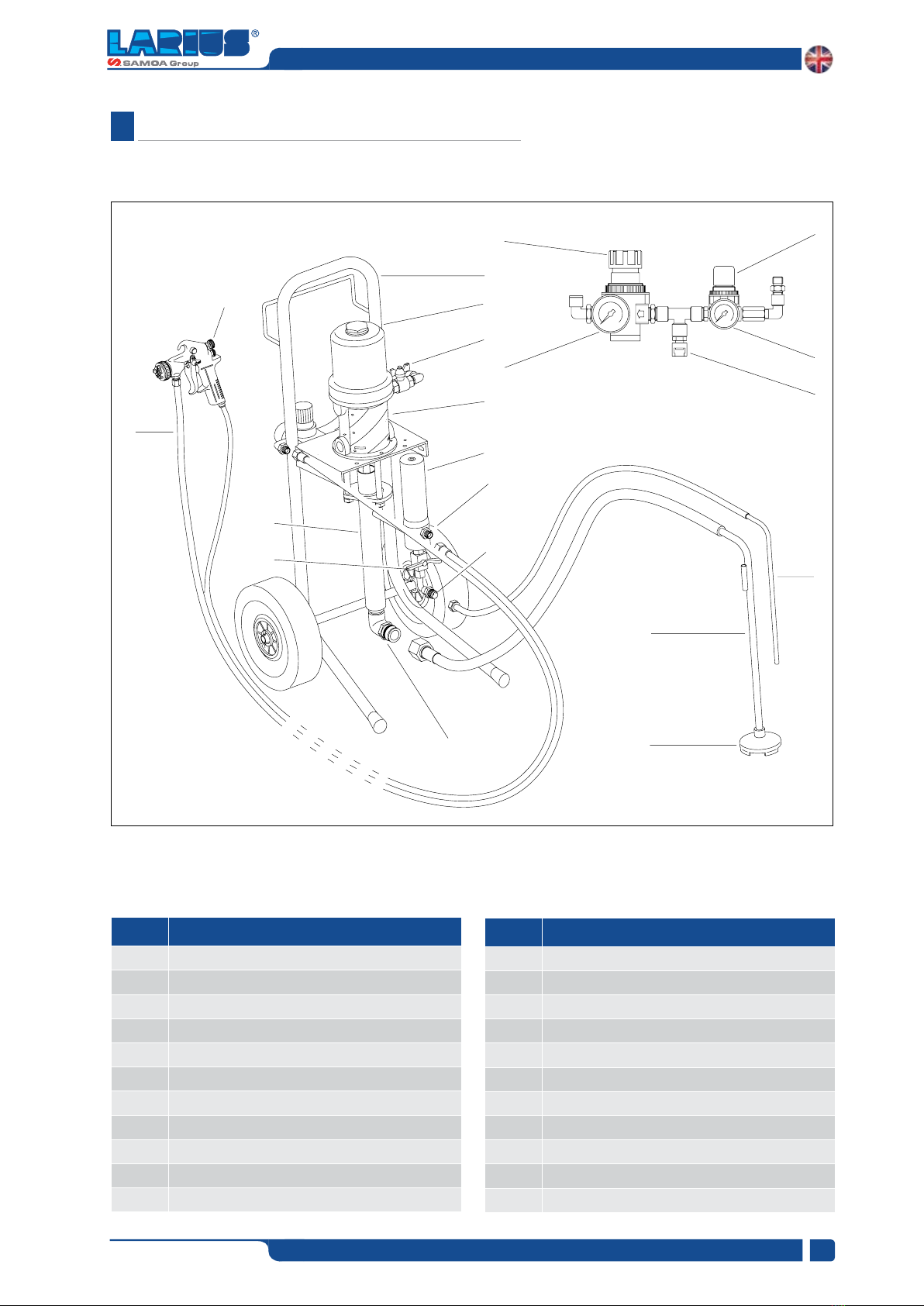
CONNEC-
TION BETWEEN PUMP, FLEXIBLE HOSE AND SPRAY GUN
BEFORE USING THE EQUIPMENT.
STANDARD KIT.
THAN THOSE RECOMMENDED IN THIS MANUAL, MAY
CAUSE DAMAGE OR INJURE THE OPERATOR.
VERY DANGEROUS. HANDLE THE FLEXIBLE HOSE CARE-
FULLY. DO NOT PULL THE FLEXIBLE HOSE TO MOVE THE
EQUIPMENT. NEVER USE A DAMAGED OR A REPAIRED
FLEXIBLE HOSE.
Readcarefullyand entirelythefollowing instructions
before using the product. Please save these
instructions in a safe place.
The unauthorised tampering/replacement of one
or more parts composing the machine, the use of
accessories,tools, expendablematerials otherthan
those recommended by the manufacturer can be a
danger of accident.
The manufacturer will be relieved from tort and
criminal liability.
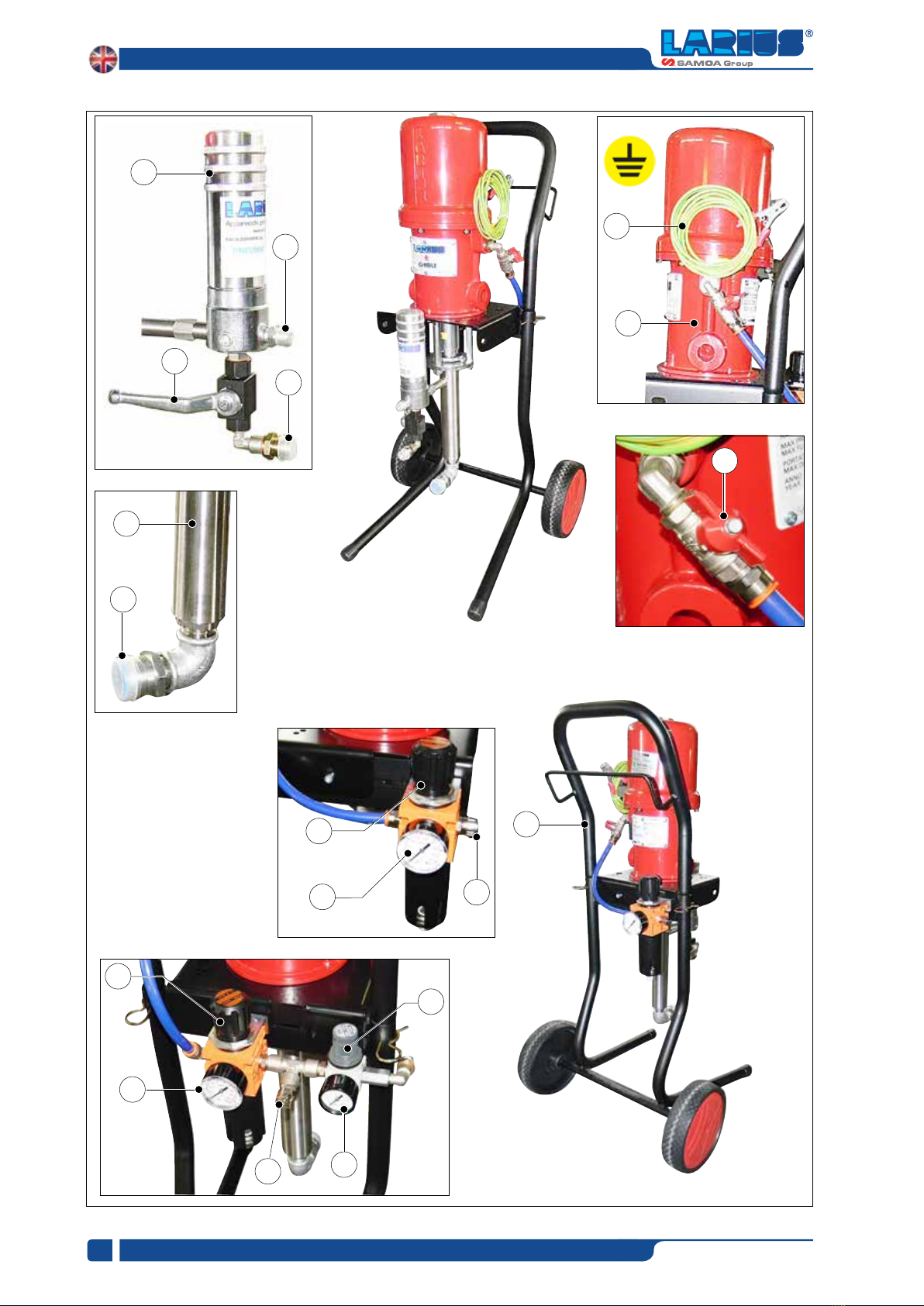
The high speed of travel of the product in the hose
can create static electricity through discharges
and sparks. It is suggested to earth the equipment.
The pump is earthed through the earth cable of
the supply.
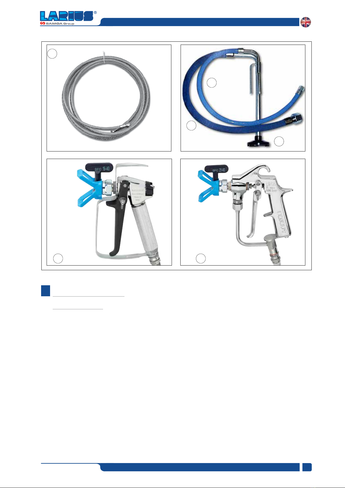
The gun is earthed through the high pressure
flexible hose.
All the conductors near the work area must be
earthed.

www.larius.com
9
GHIBLI 30:1/40:1
REV.. 01 - 03/2020 - Cod. 150088
H
H1
H2
H1
• NEVER SPRAY OVER FLAMMABLE PRODUCTS OR
SOLVENTSINCLOSEDPLACES.
• NEVERUSETHETOOLINGINPRESENCEOFPOTENTIALLY
EXPLOSIVEGAS.
Always check that the product is compatible with
the materials composing the equipment (pump,
spray gun, flexible hose and accessories) with which
it can come into contact. Never use paints or
solvents containing Halogen Hydrocarbons (as
the Methylene Chloride). If these products come
into contact with aluminium parts can provoke
dangerous chemical reactions with risk of
corrosion and explosion.
Avoid approaching too much to the pump piston
rod when the pump is working or under pressure.
A sudden movement of the piston rod can cause
wounds or finger squashing.
If the product to be used is toxic, avoid inhalation
and contact by using protection gloves, goggles
and proper face shields.
Take proper safety measures for the protection
of hearing in case of work near the plant.
CONNECTION OF SUCTION AND RECIRCULATING PIPES
• Connect the suction and recirculating pipes to the pump.
Thesuctionhosecanbelockedfingertight (H1). Useaspanner
totightentherecirculatingpipe (H2). Inbothcasesdonotuse
sealantagentsforfittingthreads.
SETTING-UP
CONNECTION TO THE FEED AIR
•Forpumpfeeduseahose(H1)withaninternaldiameterno
lowerthan10mm.
Fig. 1H
Fig. 2H

www.larius.com
10
GHIBLI 30:1/40:1
REV.. 01 - 03/2020 - Cod. 150088
"AIR
ASSISTED
AIRLESS"
H2
H1
AIR ASSI
STED
AIRLESS
H5
H3
H3 H4
H6
AIRLESS
CONNECTION OF SUCTION AND RECIRCULATING PIPES
AIRLESS version
• Connectthehighpressureflexiblehose (H3) tothepumpand
tothespraygun,payingattentiontotightenthefittingsstrongly
(the use of two spanners is suggested). Donotusesealantagents
forfittingthreads.
•Makesurethesprayguniswithouttheatomizationnozzle.
"AIR ASSISTED AIRLESS" version
Forthe"AIRASSISTEDAIRLESS"version,connecttube (H3),
aswellastheairsupplyhose (H4), totheairreducerunit(H5).
WASHING OF THE BRAND-NEW EQUIPMENT
•Theequipmenthasbeentestedatourplantwithlightmineral
oilleftinsideofthepumpingelementasprotection.Therefore,
beforesuckingtheproduct,carryoutawashingusingadiluent.
•Dipthesuctionhose (H1) intothetankofthewashing.
• Insert the recirculating pipe (H2) into a container (a metal
container is suggested).
•Opentherecirculatingcock (H6).
•Setthepumpfeedpressureatabout3barandopentheair
passagevalve.
•Thepumpwillstartworkingandwilldrainoilfromtherecirculating
pipe.Closetherecirculatingcockassoonasthecleansolvent
hascomeout.
•Liftthesolventtank’ssuctiontube.
•Leanthespraygunagainsttherimofthecontainer(H7)
and
draintheresidualoilpressingthetrigger.Releasethetriggeras
soonasthecleansolventcomesout.
•Pointthespraygunatthetankofthesolventandpressthe
triggersoastorecoverthecleansolventleftinsidethepump.
• As an accelerated working ofthepump (the pump "idles")
appears,closetheairpassagevalve.
Fig. 3H
Fig. 4H
Fig. 5H
Fig. 6H

www.larius.com
11
GHIBLI 30:1/40:1
REV.. 01 - 03/2020 - Cod. 150088
I
J
H7
I1
• Allowtheproducttocirculateforafewseconds.Thenclose
therecirculatingcock.Thepumpwillkeeponworkinguntil
thehighpressureflexiblehoseisfullofproductuptothe
spraygun.Thenthepumpwillstopautomatically.
• Increasepumpfeedpressuresoastoreachapressurevalue
toguaranteeagoodatomizationoftheproduct.
• Anirregularandmarkedsprayonthesidesindicatesalow
workingpressure.Onthecontrary,atoohighpressurecauses
ahighfog("overspray")andwasteofproduct.
• Inordertoavoidoverthicknessofpaint,letthegunadvance
sideways(right-left)whenspraying.
• Alwayspaintwithregularparallelbandscoats.
• Keep a safety and constant distance between the spray
gun and the support to be painted and keep yourselves
perpendiculartoit.
CLEANING AT THE END OF
THE WORK
• Liftthesuctionhosefromthetankoftheproduct.
• Reducethepumpfeedpressuretoabout3-4barandopen
terecirculatingcocksoastorecovertheproductleftinside
theequipment.
• Closetheairpassagevalveforpumpfeed.
• Point the spray gun at the tank of the solvent and press
thetriggersoastorecoverthecleansolventleftinsidethe
pump.
• Remove the nozzle from the spray gun (Do not forget to
clean it using a solvent!).
PREPARATION OF THE PAINT
• Makesuretheproductissuitabletobeusedwithaspray
gun.
•Mixandfiltertheproductbeforeusingit.Forfiltration,use
CLOSE-MESH(ref.214)andLARGE-MESH(ref.215)LARIUS
METEXbraids.
• Use the tooling after performing all the SETTING UP
operationsabovedescribed
• Use the supplied lubricant (I1) to facilitate the sliding of
thepistoninsidethesealpackingandtointerposetheoil
withintheair.
• Fixtheatomizationnozzleonthespraygun.Selecttheright
nozzleaccordingtothecharacteristicsofthematerialtobe
usedandtothetypeofworktobeperformed.
• Dipthesuctionandrecirculatingpipesintothetankofthe
product.
• Opentherecirculatingcock.
• Setthepumpfeedpressureatabout3-4barandopenthe
airpassagevalve.
WORKING
Make sure the product to be used is compatible
with the materials employed for manufacturing
the equipment. For this reason, please contact
the supplier of the product.
Check all the fittings for connection of the diffe-
rent components (pump, flexible hose, spray gun, etc.)
before using the equipment.
Never point the spray gun at your selves or at
other people. The contact with the cating can
cause serious injuries.
At the start of each working day, make sure that
the ring nut is filled with hydraulic oil (ref. 16325);
the oil facilitates the sliding of the piston and
prevents any material which may have leaked
out of the seals from drying once the equipment
has been shut off.
Fig. 7H
Fig. 1I

www.larius.com
12
GHIBLI 30:1/40:1
REV.. 01 - 03/2020 - Cod. 150088
K
Conservare eventuali fluidi pericolosi in contenitori
appropriati. Essi vanno eliminati in osservanza alle
leggi relative allo smaltimento dei rifiuti industriali.
K2
K1
K3
Rif. 16325
K4
K5
MATERIAL OUTPUT FILTER
ROUTINE MAINTENANCE
• Check periodically(and every time the pump is operated
after a long storage) the packing nut is not loosened, causing
otherwise the coming out of the product.
• Dip the suction hose into the tank of the washing solvent
(ensure it is compatibile with the product being used).
• Insert the recirculating hose into a container (a metal container
is recommended).
• Open the recirculating cock.
• Open the air passage valve in order to start up the pump.
• Close the recirculating cock as soon as a clean solvent
comes out.
• Lift the solvent tank’s suction tube.
• Point the spray gun at the tank of the solvent and press
the trigger so as to recover the clean solvent left inside the
pump.
• As an accelerated working of the pump (the pump "idles")
appears, close the air passage valve .
• In case of long storage, we recommend you to suck and
to leave light mineral oil inside the pumping group and the
flexible hose.
• In this case, please follow the washing procedure described
on page 8 before using the tooling.
To tighten the packing nut (K1) use wrench supplied
(K2). The packing nut must be tightened so as to avoid
wastes of product, but not excessively to avoid the
seizure of the pumping piston and the wear of seals.
In case of persistent coming out of product, replace the seals.
• Remove and clean the material suction filter (K4).
• Remove and clean the high pressure filter for material outlet
(K5).
• Check periodically the air supply to the pump. Ensure the
air is always clean and lubricated.
Store possible dangerous fluids in proper con-
tainers. Their disposal must be performed in
accordance with the regulations in force about
the industrial waste goods.
At the start of each working day, make sure that
the ring (K3) nut is filled with hydraulic oil (ref.
16325); the oil facilitates the sliding of the piston
and prevents any material which may have leaked
out of the seals from drying once the equipment
has been shut off.
Always close the compressed air supply and
release the pressure in the plant before performing
any check or maintenance of the pump.
MATERIAL SUCTION FILTER
Fig. 1K
Fig. 2K
Fig. 3K

www.larius.com
13
GHIBLI 30:1/40:1
REV.. 01 - 03/2020 - Cod. 150088
L
M
3 mm
M1
M2
M3
M4
M5
M6
L1
L2
M7
M7
M6
M8
M3
M3
DISASSEMBLY OF THE
PNEUMATIC MOTOR
• Close the compressed air supply to the pump and release
the residual pressure in the plant.
• Unscrew the motor cap (M1) and pull it upwards together
with the guide rod (M2).
• Hold the guide rod (M2) and remove the plug (M1) (using
two wrenches).
• Remove the screws (M4) and the washers (M5).
• Carefully extract the motor cylinder (M6) fom the pump.
MANUAL RESET OF THE
PNEUMATIC MOTOR
• The feed air pressure of the pump must never be higher than
the maximum value indicated in the technical data. Exceed
this value can block the valves of the pneumatic motor in
the intermediate position of the cycle reversal.
• To start again a blocked motor, close the air supply and
release pressure in the plant. This operation should allow
the recovery of the valves.
• In case the motor is blocked, proceed as follows:
- Close the air supply to the pump and release the residual
pressure in the plant;
- unscrew the motor cap (L1) and pull it upward along with the
guide rod (L2) so as to manually trigger the stroke inversion
unit;
- screw again the plug.
• Check the condition of each part of the motor.
• For any eventual replacement of the screws (M7) of the
traverse (M8), for their reassembly and correct adjustment.
Replace immediately the plug (M1) with a usual
M8 (M3)nut before the guide rod slides into the
cylinder.
Fig. 1M
Fig. 1L
Fig. 2M

www.larius.com
14
GHIBLI 30:1/40:1
REV.. 01 - 03/2020 - Cod. 150088
N
N2
3
4
56
7
N1
2
1
DISASSEMBLY OF
THE PUMPING GROUP
disassembling the pumping unit.
1
2
(N1).
3
Pull the pumping unit towards yourself so that the split
pin (N2) leaving the air valve open will
facilitate this operation
4
5
6
7
Fig. 1N
Fig. 2N
Fig. 3N

www.larius.com
15
GHIBLI 30:1/40:1
REV.. 01 - 03/2020 - Cod. 150088
OTROUBLESHOOTING
Problem Cause Solution
The pump does not start
pipe. Feed pump at minimum pressure
Disassemble the pumping group and
- Consult the paragraph "Manual reset
of the pneumatic motor
Accelerate working and no pressure
of the pump
Controllare il tubo di aspirazione
Clean and/
The pump functions, but doesn't
stop when the chamber is full (the
pump continues slowly, increasing
and/or decreasing)
Disassemble the delivery valve and

www.larius.com
16
GHIBLI 30:1/40:1
REV.. 01 - 03/2020 - Cod. 150088
Always close the compressed air supply and release the pressure in the plant before performing any check or
replacement of parts of the pump.
Problem Cause Solution
The pump works, but the flow of
product is not sufficien
Waste of product from the wet cup
The equipment does not suck the
product
The pressure of the material is signi
ficantly reduced when the trigger is
pressed

www.larius.com
17
GHIBLI 30:1/40:1
REV.. 01 - 03/2020 - Cod. 150088
SPARE PARTS
P
X
Y
S-T
R
Q
Complete pneumatic motor
pump Ghibli for TROLLEY/WALL
30:1 / 40:1
pag. 20
W
Complete filter split
galvanized and stainless
steel version
pag. 30
ZWall support
pag. 34
Complete pneumatic motor
pump Ghibli BASE 30:1 / 40:1
pag. 18
Complete trolley
pag. 33
Paint suction system
pag. 32
Air regulation group
AIRLESS version (trolley and
wall version)
pag. 26-28
Complete pumping pump Ghibli
split version and stainless steel
30:1 / 40:1
pag. 22
U-V
Air regulation group AIR
ASSISTED AIRLESS version
(for trolley and wall version)
pag. 28-29

www.larius.com
18
GHIBLI 30:1/40:1
REV.. 01 - 03/2020 - Cod. 150088
P
2
1
39
9
10
10
11
11
12
13
17
18
4
5
6
7
8
14
15
16
20
21
22
23
19
24
25
27
29
30
26
31
33
32
29
34
35
28
36
37 38 3
9
40
COMPLETE PNEUMATIC MOTOR PUMP GHIBLI 30:1 / 40:1 BASE PUMP VERSION
WARNING: always indicate code and quantity for each part required.
This manual suits for next models
1
Table of contents
Other Samoa Paint Sprayer manuals