Liquid Controls LCI40 Series User manual

1
WWW.LCMETER.COM
LCI40 Series IOM
LCI40®Series
Signal Converter for Mass Flowmeters Installation and Parts
An IDEX Energy & Fuels Business LC_LCRIIE26:V1-0716
LIQUID C O N T R O L S

2WWW.LCMETER.COM LCI40 Series IOM
The documentation is only complete when used in
combination with the relevant documentation for the
signal converter.
All rights reserved. It is prohibited to reproduce this
documentation, or any part thereof, without the prior
written authorization of Liquid Controls, LLC.
Content is subject to change without notice.
www.lcmeter.com
07/2016 LCI40
Copyright 2016 by Liquid Controls, LLC.
The most current English versions of all Liquid
Controls publications are available on our web site,
www.lcmeter.com. It is the responsibility of the local
distributor to provide the most current version of LC
manuals, instructions, and specification sheets in the
required language of the country or the language of the
end user to which the products are shipping. If there
are questions about the language of any LC manuals,
instructions, or specification sheets, please contact
your local distributor.
PUBLICATION UPDATES AND TRANSLATIONS
The documentation is only complete when used in
combination with the relevant documentation for the
signal converter.

3
WWW.LCMETER.COM
LCI40 Series IOM
TABLE OF CONTENTS
1. SAFETY INSTRUCTIONS
1.1 Software History..............................................4
1.2 Intended Use ................................................... 5
1.3 Safety Instructions From The Manufacturer.... 5
2. DEVICE DESCRIPTION
2.1 Scope of Delivery ............................................6
2.2 Device Description .......................................... 7
2.3 Field Housing ..................................................8
2.4 Name Plates ....................................................9
3. INSTALLATION
3.1 General Notes on Installation ........................10
3.2 Storage..........................................................10
3.3 Transport .......................................................10
3.4 Installation Specifications.............................. 10
3.5 Mounting of the Compact Version ................10
3.6 Mounting the Field Housing, Remote Version .. 11
4. ELECTRICAL CONNECTIONS
4.1 Safety Instructions.........................................13
4.2 Important Notes on Electrical Connection ....13
4.3 Requirements for Signal Cables
Provided by the Customer ............................13
4.4 Connecting the Signal Cables....................... 14
4.5 Grounding the Measuring Sensor ................. 16
4.6 Connecting Power, All Housing VariantS....... 16
4.7 Inputs and Outputs, Overview.......................17
4.8 Description of the Inputs and Outputs .......... 21
4. ELECTRICAL CONNECTIONS
4.9 Electrical Connection of the
Inputs and Outputs........................................24
4.10 Description of the Inputs and Outputs ........ 25
5. START-UP
5.1 Switching on the Power ................................34
5.2 Starting the Signal Converter ........................34
6.OPERATION
6.1 Display and Operating Elements...................35
6.2 Zero Calibration (Menu C1.1.1) .....................40
6.3 Menu Structure.............................................. 42
6.4 Function Tables ............................................. 45
6.5 Description of Functions ............................... 65
6.6 Status Messages and
Diagnostic Information ..................................79
6.7 Function Tests and Troubleshooting .............87
6.8 Diagnostic Functions..................................... 89
7. SERVICE
7.1 Replacing the Signal Converter Electronics..90
7.2 Sensor or Drive Coil Fault..............................91
7.3 Spare Parts Availability.................................. 92
7.4 Availability of Services...................................92
7.5 Disposal......................................................... 92
8. TECHNICAL DATA
8.1 Measuring Principle (Twin Tube)....................93
8.2 Technical Data ............................................... 95
8.3 Dimensions and Weights............................. 106

4WWW.LCMETER.COM LCI40 Series IOM
1. SAFETY INSTRUCTIONS
1.1 Software History
The “Electronic Revision” (ER) is consulted to
document the revision status of electronic equipment
according to NE 53 for all GDC devices. It is easy to
see from the ER whether troubleshooting or larger
changes in the electronic equipment have taken place
and how that has affected the compatibility.
Changes and Effect on Compatibility
1Downwards compatible changes and fault repair with no effect on operation (e.g. spelling
mistakes on display)
2-_
Downwards compatible hardware and/or software change of interfaces:
P PROFIBUS
F Foundation Fieldbus
M Modbus
X all interfaces
3-_
Downwards compatible hardware and/or software change of inputs and outputs:
I Current output
F, P Frequency / pulse output
S Status output
C Control input
CI Current input
X all inputs and outputs
4 Downwards compatible changes with new functions
5 Incompatible changes, i.e. electronic equipment must be changed.
Information
In the table below, “x” is
a placeholder for possible
multi-digit alphanumeric
combinations, depending
on the available version

5
WWW.LCMETER.COM
LCI40 Series IOM
DANGER
For devices used in hazardous
areas, additional safety notes
apply.
1.2 Intended Use
The mass flowmeters are designed exclusively to
directly measure mass flow rates, product density and
temperature as well to indirectly measure parameters
such as the total volume and concentration of
dissolved substances as well as the volume flow rate.
DANGER
For devices used in hazardous
areas, additional safety notes
apply; please refer to the Ex
documentation.
WARNING
If the device is not used according
to the operating conditions (refer
to chapter Technical data), the
intended protection could be
affected.
1. SAFETY INSTRUCTIONS

6WWW.LCMETER.COM LCI40 Series IOM
1. SAFETY INSTRUCTIONS
1.3 Safety Instructions From The Manufacturer
1.3.1 Disclaimer
The manufacturer will not be liable for any damage
of any kind by using its product, including, but
not limited to direct, indirect ,or incidental and
consequential damages.
This disclaimer does not apply in case the manufacturer
has acted on purpose or with gross negligence. In the
event any applicable law does not allow such limitations
on implied warranties or the exclusion of limitation of
certain damages, you may, if such law applies to you,
not be subject to some or all of the above disclaimer,
exclusions, or limitations.
Any product purchased from the manufacturer is
warranted in accordance with the relevant product
documentation and our Terms and Conditions of Sale.
The manufacturer reserves the right to alter the content
of its documents, including this disclaimer in any way,
at any time, for any reason, without prior notification,
and will not be liable in any way for possible
consequences of such changes.
Liquid Controls disclaims all liability for damage to
meter or accessories because of corrosion, salting-
out of product, or separation of chemicals, whether
occurring during periods of use or storage.
1.3.2 Product Liability and Warranty
The operator shall bear responsibility for the suitability
of the device for the specific purpose.
The manufacturer accepts no liability for the
consequences of misuse by the operator. Improper
installation and operation of the devices (systems)
will cause the warranty to be void. The respective
“Standard Terms and Conditions” which form the basis
for the sales contract shall also apply.
1.3.3 Information Concerning the
Documentation
To prevent any injury to the user or damage to the
device it is essential that you read the information
in this document and observe applicable national
standards, safety requirements and accident prevention
regulations.
If this document is not in your native language and if
you have any problems understanding the text, we
advise you to contact your local office for assistance.
The manufacturer can not accept responsibility for any
damage or injury caused by misunderstanding of the
information in this document.
This document is provided to help you establish
operating conditions, which will permit safe and
efficient use of this device. Special considerations and
precautions are also described in the document, which
appear in the form of icons on page 16.

7
WWW.LCMETER.COM
LCI40 Series IOM
1. SAFETY INSTRUCTIONS
1.3 Safety Instructions From The Manufacturer
1.3.4 Warning
Be Prepared
• Before using this product, read and understand the
instructions.
• All work must be performed by qualified personnel
trained in the proper application, installation, and
maintenance of equipment and/or systems in
accordance with all applicable codes and ordinances.
• When handling electronic components and boards,
always use proper Electrostatic Discharge (ESD)
equipment and follow the proper procedures
• Make sure that all necessary safety precautions have
been taken.
• Provide for proper ventilation, temperature control,
fire prevention, evacuation, and fire management.
• Provide easy access to the appropriate fire
extinguishers for your product.
• Consult with your local fire department, state, and
local codes to ensure adequate preparation.
• Read this manual as well as all the literature provided
in your owner’s packet.
• Save these instructions for future reference.
• Failure to follow the instructions set forth in this
publication could result in property damage, personal
injury, or death from fire and/or explosion, or other
hazards that may be associated with this type of
equipment.
Safely Evacuate Piping System
Before disassembly of any meter or accessory
component:
• All internal pressures must be relieved and all liquid
drained from the system in accordance with all
applicable procedures.
• Pressure must be 0 (zero) psi.
• Close all liquid and vapor lines between the meter
and liquid source.
For Safety Rules, refer to local authorities and relevant
NFPA Codes.
Failure to follow this warning could result in
property damage, personal injury, or death from
fire and/or explosion, or other hazards that may be
associated with this type of equipment.
1.3.5 Notice
This manual provides warnings and procedures that
are intended to inform the owner and/or operator of the
hazards present when using the Liquid Controls Meter
on LP-Gas and other products. The reading of thee
warnings and the avoidance of such hazards is strictly
in the hands of the owner-operators of the equipment.
Neglect of that responsibility is not within the control of
the manufacturer of the meter.
1.3.6 Publication Updates and Translations
The most current English version of all Liquid Controls
publications are available on our Web site, www.
lcmeter.com. It is the responsibility of the local
distributor to provide the most current version of Liquid
Control manuals, instructions, and specification sheets
in the required language of the country or the language
of the end user to which the products are shipping. If
there are questions about the language of any Liquid
Controls manuals, instructions, or specification sheets,
please contact you local distributor.

8WWW.LCMETER.COM LCI40 Series IOM
2. DEVICE DESCRIPTION
2.1 Scope of Delivery
Scope of Delivery
1. Device in the version as ordered
2. Documentation
3. Signal cable (only for remote
version)
Information
Inspect the cartons carefully
for damages or signs of rough
handling. Report damage to the
carrier and to the local office of the
manufacturer.
Information
Do a check of the packing list to
make sure that you have all the
elements given in the order.
Information
Look at the device nameplate to
ensure that the device is delivered
according to your order.
Check for the correct supply
voltage printed on the nameplate.
Signal Converter / Measuring Sensor Combination Possibilities
Measuring Sensor Signal Converter LCI40
Compact Remote Field Housing
LCMass®100 LCMass®140 C LCMass®140 F
LCMass®600 LCMass®640 C LCMass®640 F

9
WWW.LCMETER.COM
LCI40 Series IOM
2. DEVICE DESCRIPTION
2.2 Device Description
The mass flowmeters are designed exclusively to
directly measure mass flow rates, product density and
temperature as well to indirectly measure parameters
such as the total volume and concentration of
dissolved substances as well as the volume flow rate.
Your measuring device is supplied ready for operation.
The factory settings for the operating data have been
made in accordance with your order specifications.
Device Versions
1. Compact version
2. Measuring sensor with connection box
3. Field housing
The following versions are available:
• Compact version (the signal converter is mounted
directly on the measuring sensor)
• Remote version (electrical connection to the
measuring sensor via field current and signal cable)

10 WWW.LCMETER.COM LCI40 Series IOM
2.3 Field Housing
2. DEVICE DESCRIPTION
Construction of the Field Housing
1. Cover for electronics and display
2. Cover for power supply and inputs/outputs terminal
compartment
3. Cover for measuring sensor terminal compartment
4. Cable entry for measuring sensor signal cable
5. Cable entry for measuring sensor field current cable
6. Cable entry for power supply
7. Cable entry for inputs and outputs
8. Mounting plate for pipe and wall mounting
Information
Each time a housing cover is
opened, the thread should be
cleaned and greased. Use only
resin-free and acid-free grease.
Ensure that the housing gasket
is properly fitted, clean, and
undamaged.

11
WWW.LCMETER.COM
LCI40 Series IOM
2. DEVICE DESCRIPTION
2.4 Nameplates
2.4.1 Example of a Nameplate
Example of a Nameplate
1. Approvals-related thresholds
2. Additional information on documentation, calibration and
patents
3. Protection category
4. Electrical connection data
5. Software and hardware revision (Electronics Revision), CG
number, order number for signal converter and measuring
sensor
6. Product description
7. Manufacturer and manufacturer logo
Information
Look at the device nameplate to
ensure that the device is delivered
according to your order.
Check for the correct supply
voltage printed on the nameplate.
2.4.2 Electrical Connection Data of
Inputs/Outputs (Example of Basic
Version)
• A = active mode; the signal converter supplies the
power for connection of the subsequent devices
• P = passive mode; external power supply required
for operation of the subsequent devices
• N/C = connection terminals not connected
Example of a Nameplate for Electrical Connection Data of
Inputs and Outputs
1. Power supply (AC: L and N; DC: L+ and L-; PE for ≥24
VAC; FE for ≤24 VAC and DC)
2. Connection data of connection terminal D/D-
3. Connection data of connection terminal C/C-
4. Connection data of connection terminal B/B-
5. Connection data of connection terminal A/A-; A+ only
operable in the basic version
➀
➁
➆
➅
➄
➃
➂
Liquid Controls LLC
Lake Bluff, IL 60044-2242
12 WWW.LCMETER.COM LCI40 Series IOM
3.1 General Notes on Installation
3. INSTALLATION
Information
Inspect the cartons carefully
for damages or signs of rough
handling. Report damage to the
carrier and to the local office of the
manufacturer.
Information
Do a check of the packing list to
make sure that you have all the
elements given in the order.
Information
The following precautions must be taken to ensure reliable installation.
• Makesurethatthereisadequatespacetothesides.
• Protectthesignalconverterfromdirectsunlightandinstallasunshadeifnecessary.
• Signalconvertersinstalledincontrolcabinetsrequireadequatecooling,e.g.byfanorheat
exchanger.
• Donotexposethesignalconvertertointensevibrations.Themeasuringdevicesaretestedfor
a vibration level in accordance with IEC 68-2-64.
Information
Look at the device nameplate to
ensure that the device is delivered
according to your order.
Check for the correct supply
voltage printed on the nameplate.
3.2 Storage
• Store the device in a dry, dust-free location.
• Avoid continuous direct sunlight.
• Store the device in its original packing.
• Storage temperature: -58°F to +158°F / -50°C to +70°C
3.3 Transport
Signal Converter
• No special requirements.
Compact Version
• Do not lift the device by the signal converter housing.
• Do not use lifting chains.
• To transport flange devices, use lifting straps. Wrap
these around both process connections.
3.4 Installation Specifications

13
WWW.LCMETER.COM
LCI40 Series IOM
3.5 Mounting of the Compact Version
Information
The signal converter is mounted directly on the measuring sensor. For installation of the
flowmeter, please observe the instructions in the supplied product documentation for the
measuring sensor.
3. INSTALLATION
3.6 Mounting the Field Housing, Remote Version
Information
Assembly materials and tools are
not part of the delivery. Use the
assembly materials and tools in
compliance with the applicable
occupational health and safety
directives.
3.6.2 Wall Mounting
3.6.1 Pipe Mounting
Pipe Mounting of the Field Housing
1. Fix the signal converter to the pipe.
2. Fasten the signal converter using standard U-bolts
and washers.
3. Tighten the nuts.
Wall Mounting of the Field Housing
1. Prepare the holes with the aid of the mounting plate. For
further information refer to Mounting plate, field housing
on page 133.
2. Use the mounting material and tools in compliance with
the applicable occupational health and safety directives.
3. Fasten the housing securely to the wall.
Mounting Multiple Devices Next to Each Other
a ≥23.6” / 600 mm
b ≥9.8” / 250 mm
14 WWW.LCMETER.COM LCI40 Series IOM
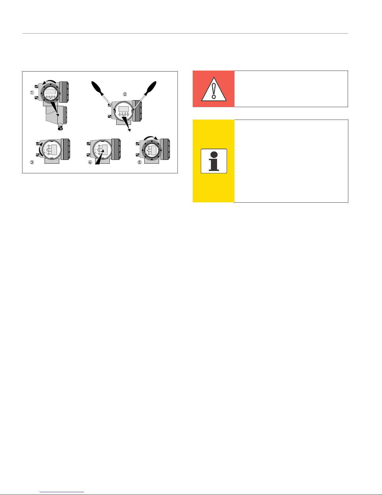
3.6.3 Turning the Display of the Field Housing Version
3. INSTALLATION
Turning the Display of the Field Housing
Version
The display of the field housing version can be turned
in 90° increments.
1. Unscrew the cover from the display and operation
control unit.
2, Using a suitable tool, pull out the two metal puller
devices to the left and right of the display.
3. Pull out the display between the two metal puller
devices and rotate it to the required position.
4. Slide the display and then the metal puller devices
back into the housing.
5. Re-fit the cover and tighten it by hand.
CAUTION
The ribbon cable of the display must
not be folded or twisted repeatedly.
Information
Each time a housing cover is
opened, the thread should be
cleaned and greased. Use only
resin-free and acid-free grease.
Ensure that the housing gasket
is properly fitted, clean and
undamaged.
3.6 Mounting the Field Housing, Remote Version

15
WWW.LCMETER.COM
LCI40 Series IOM
4.1 Safety Instructions
DANGER All work on the electrical
connections may only be carried out with
the power disconnected. Take note of the
voltage data on the nameplate!
DANGER Observe the national regulations
for electrical installations!
DANGER For devices used in hazardous
areas, additional safety notes apply; please
refer to the Ex documentation.
4. ELECTRICAL CONNECTIONS
4.3 Requirements for Signal Cables Provided by the Customer
DANGER Observe without fail the local
occupational health and safety regulations.
Any work done on the electrical components
of the measuring device may only be carried
out by properly trained specialists.
Information Look at the device nameplate
to ensure that the device is delivered
according to your order.
Check for the correct supply voltage printed
on the nameplate.
4.2 Important Notes on Electrical Connection
DANGER Electrical connection is carried
out in conformity with the VDE 0100
directive “Regulations for electrical power
installations with line voltages up to 1000 V”
or equivalent national regulations.
CAUTION
•Use suitable cable entries for the various
electrical cables.
•The measuring sensor and signal
converter have been configured together
at the factory. For this reason, please
connect the devices in pairs.
Specifications for Standard Signal Cables
• 5 twisted pair circuits (24 AWG)
• Insulation thickness of cables: ≥0.008” / 0.2 mm)
• Each cable pair shielded with foil and drain wire
• Overall foil/braid shield
• Casing color: grey
• Color of wires:
Pair 1: yellow/black
Pair 2: green/black
Pair 3: blue/black
Pair 4: red/black
Pair 5: white/black
• Test voltage: ≥100 VAC
• Temperature range: -40°F to +185°F / -40°C to +85°C
• Capacity between cables: ≤41 pF/m
• Capacity compared to shielding: ≤73 pF/m
• Inductance: ≤0.8 μH/m
Specifications for Cables in Hazardous Areas
• 5 twisted pair circuits (24 AWG)
• Insulation thickness of cables: ≥0.008” / 0.2 mm)
• Each cable pair shielded with foil and drain wire
• Overall foil/braid shield
• Casing color: blue
• Color of wires:
Pair 1: yellow/black
Pair 2: green/black
Pair 3: blue/black
Pair 4: red/black
Pair 5: white/black
• Test voltage: ≥100 VAC
• Temperature range: -40 to +85°C / -40 to +185°F
• Capacity between cables: ≤41 pF/m
• Capacity compared to shielding: ≤73 pF/m
• Inductance: ≤0.8 μH/m

16 WWW.LCMETER.COM LCI40 Series IOM
4.4 Connecting the Signal Cables
DANGER Cables may only be connected
when the power is switched off.
DANGER The device must be grounded
in accordance with regulations in order to
protect personnel against electric shocks.
DANGER For devices used in hazardous
areas, additional safety notes apply; please
refer to the Ex documentation.
WARNING Observe without fail the local
occupational health and safety regulations.
Any work done on the electrical components
of the measuring device may only be carried
out by properly trained specialists.
4. ELECTRICAL CONNECTIONS
Cable Cable Connection Terminal
Cable Pair Color
1 yellow X1 SA+
1 black X1 SA-
2 green X1 SB+
2 black X1 SB-
3 blue X2 T1
3 black X2 T2
4 red X2 T3
4 black X2 T4
5 white X3 DR+
5 black X3 DR-
Connection of Signal Cable - Field Housing and Connection
Box for Sensor
1. Unscrew the terminal compartment cover.
2. Pass the prepared signal cable through the cable entry.
3. Secure the signal cable using the clip.
4. Connect the electrical conductors as shown. The shielding
must also be connected to the spring terminal.
5. Re-fit the cover and tighten it by hand.
4.4.1 Connection of Signal Cable - Field Housing and
Connection Box for Sensor
Information
Each time a housing cover is
opened, the thread should be
cleaned and greased. Use only
resin-free and acid-free grease.
Ensure that the housing gasket
is properly fitted, clean and
undamaged.

17
WWW.LCMETER.COM
LCI40 Series IOM
4.4.2 Connection Diagram
4. ELECTRICAL CONNECTIONS
Connection Diagram
1. Terminal compartment for signal converter
2. Terminal compartment for measuring sensor
3. Connect shielding to spring terminal (drain wire and overall shield)
DANGER
The device must be grounded in
accordance with regulations in
order to protect personnel against
electric shocks.
Cable Cable Connection Terminal
Cable Pair Color
1 yellow X1 SA+
1 black X1 SA-
2 green X1 SB+
2 black X1 SB-
3 blue X2 T1
3 black X2 T2
4 red X2 T3
4 black X2 T4
5 white X3 DR+
5 black X3 DR-
4.4 Connecting the Signal Cables

18 WWW.LCMETER.COM LCI40 Series IOM
4. ELECTRICAL CONNECTIONS
4.5 Grounding the Measuring Sensor
DANGER
There should be no difference in
potential between the measuring
sensor and the housing or
protective earth of the signal
converter!
DANGER
For devices used in hazardous
areas, additional safety notes
apply; please refer to the Ex
documentation.
DANGER
The device must be grounded in
accordance with regulations in
order to protect personnel against
electric shocks.
4.6 Connecting Power, All Housing Variants
• The measuring sensor must be properly grounded.
• The grounding cable should not transmit any
interference voltages.
• Do not use the grounding cable to connect more than
one device to ground.
• The measuring sensors are connected to ground by
means of a functional grounding conductor FE.
• In hazardous areas, grounding is used at the same
time for equipotential bonding. Additional grounding
instructions are provided in the separate “Ex
documentation”, which are only supplied together
with hazardous area equipment.
• The protection category depends on the housing
versions (IP65 to 67 to IEC 529 / EN 60529 or
NEMA4/4X/6).
• The housings of the devices, which are designed
to protect the electronic equipment from dust and
moisture, should be kept well closed at all times.
Creepage distances and clearances are dimensioned
to VDE 0110 and IEC 664 for pollution severity 2.
Supply circuits are designed for overvoltage category
III and the output circuits for overvoltage category II.
• Fuse protection (IN ≤16 A) for the infeed power
circuit, as well as a separator (switch, circuit breaker)
to isolate the signal converter must be provided close
to the device. The separator must be marked as the
separator for this device.

19
WWW.LCMETER.COM
LCI40 Series IOM
4.7 Inputs and Outputs, Overview
4. ELECTRICAL CONNECTIONS
100 to 230 VAC (tolerance range: -15% / +10%)
• Note the power supply voltage and frequency (50 to
60 Hz) on the nameplate.
• The protective ground terminal PE of the power supply
must be connected to the separate Uclamp terminal in
the terminal compartment of the signal converter
24 VDC (tolerance range: -55% / +30%)
24 VAC/DC (tolerance ranges: AC: -15% /
+10%; DC: -25% / +30%)
• Note the data on the nameplate!
• For measurement process reasons, a functional
ground FE must be connected to the separate
U-clamp terminal in the terminal compartment of the
signal converter.
• When connecting to functional extra-low voltages,
provide a facility for protective separation (PELV) (acc.
to VDE 0100 / VDE 0106 and/or IEC 364 / IEC 536 or
relevant national regulations).
Information
240 VAC+5% is included in the
tolerance range.
Information
For 24 VDC, 12 VDC-10% is
included in the tolerance range.
Power Supply Connection
1. 100 to230 VAC (-15% / +10%), 22 VA
2. 24 VDC (-55% / +30%), 12 W
3. 24 VAC/DC (AC: -15% / +10%; DC: -25% / +30%), 22 VA
or 12 W
4.6 Connecting Power, All Housing Variants
4.7.1 Combinations of the Inputs/Outputs (I/Os)
This signal converter is available with various input/output combinations.
Modular Version
• Depending on the task, the device can be configured
with various output modules.
Bus Systems
• The device allows intrinsically safe and non
intrinsically safe bus interfaces in combination with
additional modules.
• For connection and operation of bus systems, please
note the separate documentation.
Ex Option
• For hazardous areas, all of the input/output variants
for the housing designs C and F with terminal
compartment.
Basic Version
• Has 1 current output, 1 pulse output and 2 status
outputs / limit switches.
• The pulse output can be set as status output/limit
switch and one of the status outputs as a control
input.
Ex i Version
• Depending on the task, the device can be configured
with various output modules.
• Current outputs can be active or passive.
• Optionally available also with Foundation Fieldbus
and PROFIBUS PA

20 WWW.LCMETER.COM LCI40 Series IOM
4. ELECTRICAL CONNECTIONS
4.7.2 Description of the CG Number
The last 3 digits of the CG number (5, 6 and 7) indicate
the assignment of the terminal connections. Please
refer to the following examples.
Marking (CG Number) of the Electronics Module and Input/
Output Variants
1. ID number: 3
2. ID number: 0 = standard; 9 = special
3. Power supply option
4. Display (language versions)
5. Input/output version (I/O)
6. 1st optional module for connection terminal A
7. 2nd optional module for connection terminal B
The last 3 digits of the CG number (5, 6 and 7) indicate
the assignment of the terminal connections. Please
refer to the examples.
CG Number Examples
CG 330 11 100
100 to 230 VAC & standard display;
basic I/O: Iaor Ip& Sp/Cp& Sp& Pp/
Sp
CG 330 11 7FK
100 to 230 VAC & standard display;
modular I/O: Ia& PN/SNand optional
module PN/SN& CN
CG 330 81 4EB
24 VDC & standard display; modular
I/O: Ia& Pa/Saand optional module
Pp/Sp& Ip
Description of Abbreviations and CG Identifier for Possible Optional Modules on Terminals A and B
Abbreviation Identifier for CG No. Description
IaA Active current output
IpB Passive current output
Pa/ SaC Active pulse output, frequency output, status output or limit switch (changeable)
Pp/ SpE Passive pulse output, frequency output, status output or limit switch (changeable)
CaG Active control input
CpK Passive control input
- 8 No additional module installed
- 0 No further module possible
4.7 Inputs and Outputs, Overview
Table of contents
Other Liquid Controls Media Converter manuals


