PEC MACC User manual

- 2 -
PEC MACC DC Power Supply
Index
Section and Title Page
1. INTRODUCTION .................................................................................................................... 4
1.1 Scope............................................................................................................................................4
1.2 General Description of the MACC ..............................................................................................4
1.2.1 Power Conversion System...................................................................................................4
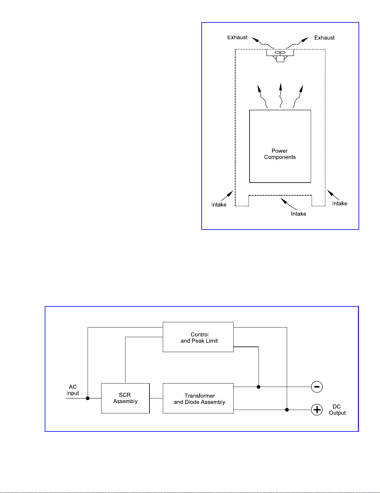
1.2.2 Cooling System ...................................................................................................................4
1.2.3 Control System ....................................................................................................................4
2. INSTALLATION ...................................................................................................................... 5
2.1 Inspection and Storage.................................................................................................................5
2.2 Handling the MACC ....................................................................................................................6
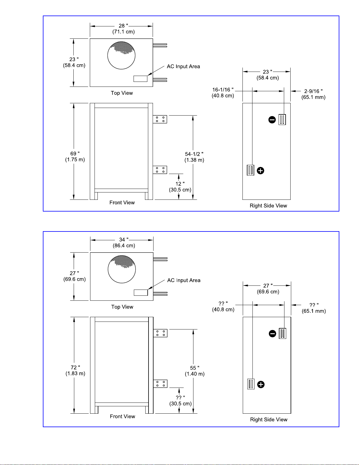
2.3 Cabinet Size, Weight, and Input KVA.........................................................................................6
2.4 Location ........................................................................................................................................6
2.4.1 Air-Cooled Converter..........................................................................................................8
2.5 Electrical ......................................................................................................................................8
2.5.1 A.C. Input Connection.........................................................................................................8
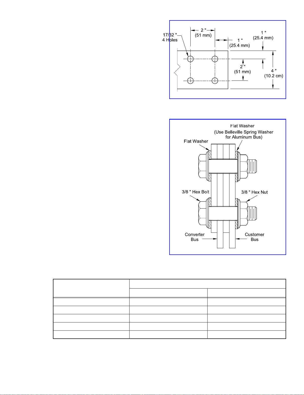
2.5.2 DC Output Connections ......................................................................................................9
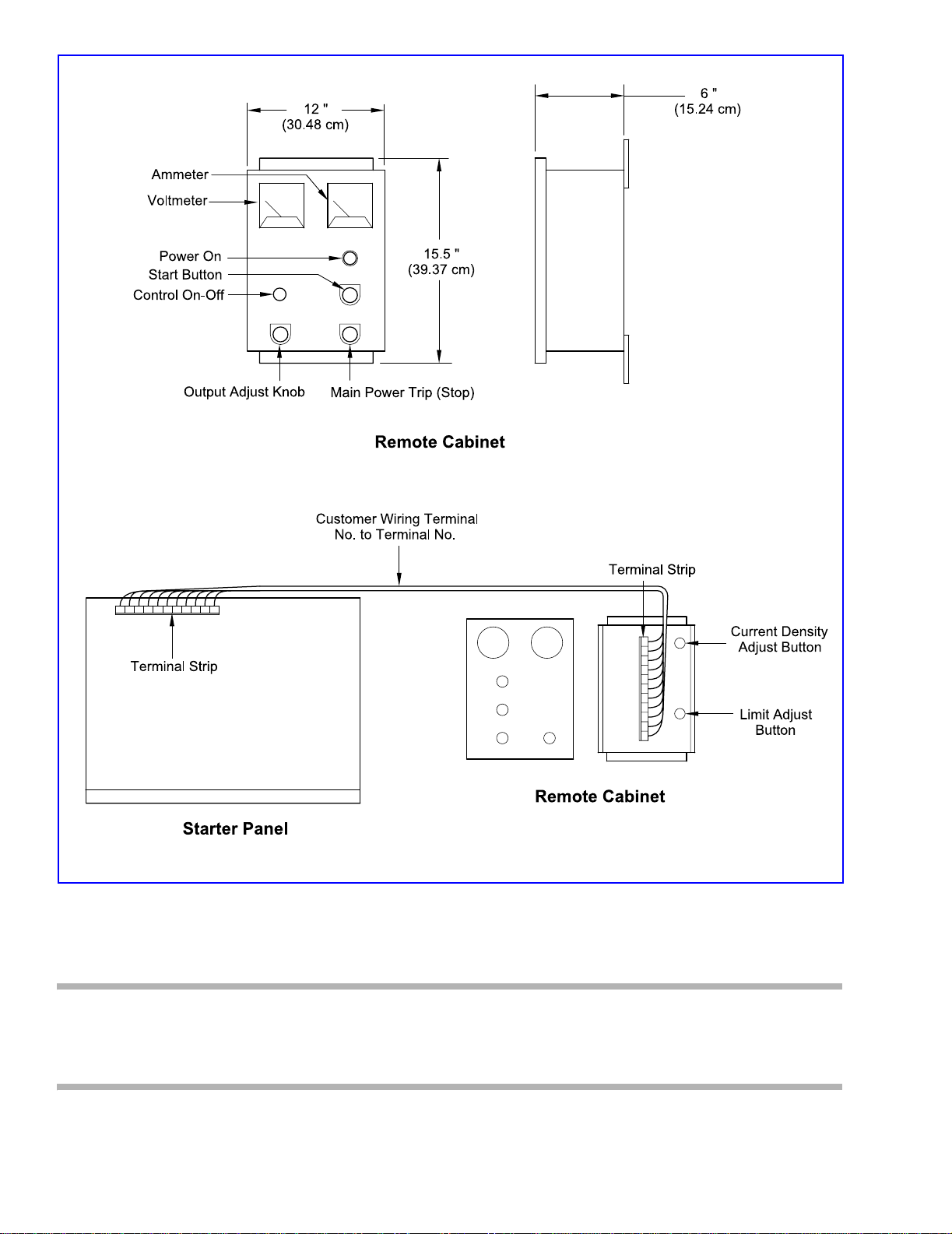
2.5.3 Connections for Remote Control Converter........................................................................9
3. OPERATION ...........................................................................................................................11
3.1 Component Operation ...............................................................................................................11
3.1.1 Magnetic Starter ................................................................................................................11
3.1.2 Line Current Transformers ................................................................................................11
3.1.3 Silicon Controlled Rectifier...............................................................................................12
3.1.4 Main Transformer..............................................................................................................13
3.1.5 Diode Assembly ................................................................................................................14
3.1.6 Control Transformer..........................................................................................................14
3.1.7 Protective Devices .............................................................................................................14
3.2 Cooling System..........................................................................................................................15
3.2.1 Control Operation..............................................................................................................15
3.2.2 Control Function................................................................................................................15
3.3 Converter Operation...................................................................................................................17
3.3.1 Turn-On Procedure............................................................................................................17
3.3.2 Automatic Voltage with Current Limit Operation Adjustment Procedure .......................17
3.3.3 Automatic Average Current Density Control with Current Limit Adjustment Procedure18
3.3.4 Automatic Current Control with Voltage Limit Adjustment Procedure ...........................19
3.3.5 Conversion to Current Mode of Control ...........................................................................19
3.3.6 Turn-Off Procedure ...........................................................................................................19

Section and Title
P
age
4. MAINTENANCE 20
4.1 Cabinet 20
4.2 Connections. 20
4.3 Control Connections 20
4.4 Control Checkpoints . 20
4.5 Cooling. 21
4.5.1 Power Components 21
4.5.2 Replacement of Diodes and Thyristors (SCR's) 21
4.6 AC1 Electronic Control Board (McTrigger). 23
4.7 Troubleshooting . 23
5. REPLACEMENT PARTS 25
5.1 Parts List 25
It must be understood that these instructions cannot cover all details or variations on equipment,
nor provide for every possible contingency in connection with installation operation or
maintenance. When the rectifier is installed, it will require little attention.
Should further information be desired or particular problems arise which are not covered herein,
please contact:
Process Electronics Corporation.
100 Brickyard Road
Mount Holly, North Carolina 28120
704-827-9019
- 3 -

- 4 -
1. INTRODUCTION
1.1 Scope
This manual describes the PEC Solid State Converter, MACC and provides information for its
installation, operation and maintenance.
1.2 General Description of the MACC
The PEC MACC is an air cooled, DC power supply designed to give a specified output voltage and
current to cover a wide range of applications. Its overall size and weight saves valuable floor space.
1.2.1 Power Conversion System
The power conversion section of the PEC MACC is completely solid state employing silicon
controlled rectifiers (SCR’s) as the voltage and current controlling elements and parallel sets of
silicon diodes as the rectifying elements. See Figure 1. The primary of the main transformer is
connected in a solid delta with the SCR’s connected in inverse parallel sets in the line. The
secondary connection is a six phase, single way.
1.2.2 Cooling System
The Udylite MACC utilizes air cooling to maintain proper operating temperature. See Figure 2.
Water connections are not required.
1.2.3 Control System
Input power is applied to the PEC MACC through power contacts, usually a magnetic starter, and
the output power is controlled by a completely solid state control board to maintain the output at a
preset value. A unique peak limit circuit offers overload protection within a half cycle of fault
current for either external or internal faults. See Figure 3.
Figure 1 Power Conversion System Block Diagram

- 5 -
2. INSTALLATION
2.1 Inspection and Storage
As all units are shipped F.O.B., our plant,
it is suggested that the shipping containers
be removed and the converter inspected for
possible damage during shipment. If any
damage is found, the purchaser must
handle the claim, and the carrier contacted
immediately. the udylite service
department should be notified if the nature
of the damage is such that operation of the
converter has been impaired.
Inspection of the interior of the converter
and the control panel can be done by
removing the front and rear. The panels
can be taken off by loosening and
removing the retaining screws and lifting
the panels, swinging the lower portion over
the bottom retainer.
All connections between the magnetic
starter, fuses, SCR assembly, main
transformer, diodes and DC bus should be
checked in case excessive vibration during
shipment resulted in loosening them.
If it is necessary to store the unit for a period of time before it is installed, be sure to place the
converter in a clean, dry area. To prevent excessive dust from accumulating on the unit, it is
advisable to protect the converter by placing it in the original shipping container.
Figure 2 Cooling System
Figure 3 Control System Block Diagram

- 6 -
2.2 Handling the MACC
The MACC unit must be handled at all times with the same care that would be given any piece of
precision electrical equipment.
Care must be exercised in lifting the converter. Weight distribution varies depending on the size of
the cabinet. Cabinets can be lifted by means of a fork-lift truck of the proper size.
2.3 Cabinet Size, Weight, and Input KVA
2.4 Location
Proper location of the MACC unit will extend its operating life. Normal precautions should be
taken to protect the unit from corrosive conditions and improper ventilation. Sufficient clearance
(12" minimum) must be allowed at the front, rear and sides for maintenance and air flow.
Output Amp/Volt Cabinet Size Weight in Lbs. (Approximate) Input KVA
500/6
See Figure 4-A
635 5
96857
12 705 8.5
18 745 12
24 795 15.5
750/6
See Figure 4-A
695 7.5
9 720 10.5
12 755 12.5
18 845 18
24 945 23.5
1000/6
See Figure 4-A
720 10
978514
12 820 17
18 955 24
24 1095 31
1500/6
See Figure 4-B
850 13.5
995019
12 1030 24
18 1220 36
24 1500 47
Table 1 Cabinet Size and Weight Comparison to Input

- 7 -
Figure 4-A Cabinet Size for 500 to 1000 Volt Output Model
Figure 4-B Cabinet Size for 1500 Volt Output Model

- 8 -
2.4.1 Air Cooled Converter
Convection or forced air is used to cool the power components of the converter. Ambient
temperature should not be allowed to exceed 105 ° F (40 ° C). In general, do not locate the
converter:
a) Close to heat generating equipment such as heaters or boilers.
b) Where subject to splashing or dripping.
c) Next to a wall or area preventing full air intake or exhaust.
d) In areas where intake suction may pull in excessive dust, moisture or corrosive fumes.
e) Where a combustible atmosphere exists.
Air intake is at the bottom, front and rear of the converter and air exhaust is at the top.
2.5 Electrical
Check the converter data plate to be sure that the rated input voltage and frequency match the
available power supply. If the supply voltage or frequency differ from the rated input voltage or
frequency, the PEC office should be contacted to advise the necessary changes before the unit can
be operated. The converter should not be connected under any circumstances to a source which
does not match the data plate rating without the approval of Udylite.
CAUTION
The input wiring and installation should
conform to the National Electrical Code,
and or local codes as required.
2.5.1 A.C. Input Connection
The primary input connections can be made
through the top of the unit. Connections for
the control wiring can also be made through
the top of the unit at the terminal strip located
on the starter control panel.
Connect properly sized wire cable to the
magnetic starter located on the starter control
panel as shown in Figure 5.
NOTE: A grounding lug is
provided. Proper grounding
is required for control opera-
tion. Figure 5 Cabinet Input Connection

- 9 -
2.5.2 DC Output Connections
The DC terminal assembly is 1/4-inch x 4-
inch copper bus bar, punched with a standard
four hole pattern. See Figure 6.
Additional bus required for the tank
connection may be aluminum or copper. If
aluminum, the bus should be plated at the
connection ends to decrease contact resistance.
A joint compound should be used before
bolting the bus bars together. Belleville
washers should be used at the bolted
connections of aluminum bus to prevent
loosening of the bus connections due to
terminal cycling. See Figure 7.
2.5.3 Connections for Remote Control Converter
The indicating and controlling elements for the
remote controlled units are mounted in a Nema
12 enclosure. The enclosure should be
mounted close to the operator's normal
position.
Connections from the converter are made to a
terminal strip mounted on sub-panel inside the
enclosure. See Figure 8. The wiring diagram
included with each converter shows the
number of wires required to connect the
converter and control unit together.
It is good practice to include a spare wire or
two for future requirements.
The ammeter leads should be sized according
to Table 2.
NOTE: A grounding lug is provided. Proper grounding is required for control
operation.
Wire Size
Length of Lead Run
Feet Meters
No. 14 0 - 15 0 - 4.5
No. 12 16 - 25 4.8 - 7.5
No. 10 26 - 40 7.2 - 12
No. 8 41 - 60 12.3 - 18.2
No. 6 61 - 100 18.5 - 30.5
Table 2 Ammeter Lead Lengths Comparison to Wire Size
Figure 6 DC Terminal Assembly
Figure 7 Customer Bus Connection

- 10 -
CAUTION
The input wiring and installation should conform to the National Electrical Code, and or
local codes as required.
Figure 8 Remote Control Converter Interconnection

- 11 -
3. OPERATION
3.1 Component Operation
3.1.1 Magnetic Starter
Three phase input power is applied to the converter through the magnetic starter. It also provides
protection in the event of a major component failure or line fault. The power contacts are actuated
by energizing a magnetic coil. A normally-open contact on the main starter, or contactor, is used
to apply power to the magnetic coil, holding the power contacts in until the coil is de-energized and
the power contacts open, removing the converter from the power line. See Figure 9.
3.1.2 Line Current Transformers
As part of the peak limit circuit, the line current transformers (1,2,3 CT) continuously monitor the
input line current while the converter is operating.
Figure 9 Converter Wiring Diagram

- 12 -
3.1.3 Silicon Controlled Rectifier
The silicon controlled rectifier (SCR) is a
regenerative semiconductor switch. See
Figure 10. It is a silicon diode with a third
element, a gate, which controls the flow of
current through the SCR. The gate
determines the point in each half cycle
when the SCR will "fire" or start to
conduct.
Without a gate signal, the SCR blocks the
flow of current in both directions. Not until
a signal is applied to the gate does the SCR
behave like a diode.
SCR firing is accomplished by introducing
a DC voltage between the gate and the
cathode. Conduction through the SCR
starts within microseconds after voltage is
applied between gate and cathode. When
sufficient current has started to flow
through the SCR, it "latches" into
conduction until the current falls below the
value of holding current at the end of that
half cycle. Holding current is the current
necessary to keep the SCR latched in
conduction. When the SCR stops
conducting, it returns to the blocking state
and will not turn again until the gate is
"pulsed" and the anode is positive with the
respect to the cathode.
Figure 11 shows two SCR’s connected in
a back-to-back arrangement. SCR1 will
conduct current when T1 is positive with
respect to T2. SCR2 will conduct current in
the opposite direction when T2 is positive
with respect to T1. Assuming that voltage
is applied between gate and cathode at
midpoint in each half cycle, 90 ° of
conduction angle can be obtained for each
SCR resulting in a current flow through the
load as shown in Figure 12. Therefore, it is
possible by introducing gate-cathode
voltage at other times during the half cycle
to control the time the SCR’s are "on" in
each half cycle and vary the load current.
Figure 10 Silicon Controlled Rectifier (SCR)
Figure 11 Two SCR’s in Back-to-Back
Arrangement
Figure 12 SCR Current Flow (90 ° Phase Angle)

- 13 -
In the MACC the SCR’s are connected in the back-to-back arrangement and placed in the line. The
transformer primary is connected in a solid delta. See Figure 13.
The DV/DT and pulse transformer boards provide both the controlling gate-cathode pulses for
varying the converter output, and DV/DT protection for the SCR from line voltage transients.
3.1.4 Main Transformer
The main transformer converts the high voltage, low current input from the controlling SCR’s into
a low voltage, high current output to the diode assembly. The main transformer is designed
specifically for each particular MACC rating.
Figure 13 DV/DT and Pulse Transformer Boards

- 14 -
3.1.5 Diode Assembly
The diode assembly of the converter is completely solid state employing parallel sets of silicon
diodes as the rectifying elements. See Figure 14. A six-phase single way rectifier connection is
employed.
The shunt provides the current feedback for the control and also the signal for the indicating
ammeter. The DC voltage output provides the voltage feedback for the control.
3.1.6 Control Transformer
Steps down the primary line voltage to 110 Volts for use in the control circuit.
3.1.7 Protective Devices
These devices provide protection for the converter.
A. Main Line Overload
A thermal type relay which opens when excessive current is drawn from the main line by the
converter. A normally-closed contact in series with the starter or contactor magnetic coil will open,
de-energize the coil and drop the converter off the line. The relay contacts must reset before the
converter can be re-started. A starter will have the thermal overload relays integral to the starter
while a contactor will use current transformers and separate overload relays.
Figure 14 Diode Assembly

- 15 -
B. Peak Limit Control
In the event of excessive instantaneous line current due to either an internal or external fault, the
current is electronically interrupted after a single half cycle (worst case) of fault current. The
control will then automatically "ease" the converter back on while continuing to monitor the line
current. The control will limit the peak input current to a safe preset level and after 5 seconds, if
the fault is not cleared, will turn the converter off. In case of a short on the output of the converter,
the normal current limit control will take over and maintain the converter average output current
at rated value.
C. Thermal Overload
Normally-closed thermal overload are used in the converter. Mounted on the diode heat sink they
will open and shut the converter off if the stud temperature is excessive (approximately 230 ° F).
3.2 Cooling System
The MACC converter is air cooled, requiring very little maintenance.
The air enters the cabinet through a screened opening in the bottom. The heated air generated from
the power components rises and exits through the top of the cabinet. It is important therefore, to
keep a minimum clearance of 12" between walls, etc.
Air at ambient or room temperature is used as the cooling medium. Therefore, the ambient air
temperature should not exceed 104 ° F (40° C) for proper operation of the converter.
3.2.1 Control Operation
A. AC1 Control Board
Continuously monitors the current transformer (1,2,3 CT) output while the converter is operating.
In the event of an external or internal fault, the peak limit circuitry will shut the converter off. The
board also accepts the feedback signals from the DC bus and shunt to provide reference levels to
control the converter output. By controlling the firing of the line SCR’s, the control board varies
the converter output voltage and current. Using the feedback signals, the converter output can be
controlled and held constant at: voltage with current limiting, average current density with current
limiting or current with voltage limiting. The board provides the references controlling voltage and
accepts the control input from the potentiometers.
3.2.2 Control Function
A. Automatic Voltage Control with Current Limiting
The function of this control is to maintain the converter output voltage at a value preset by the
operator's control knob. The preset value of output voltage will be held constant within -+ 1% of
the converter's full rated output voltage over a range of 10% to 100% of output current under
varying load conditions. For example, with a 1000 Amp @ 12 Volt unit, the output voltage will be
held constant -+ 0.12 Volts over range of operation from 10 Amp to 1000 Amp. The voltage will
remain constant throughout the operational cycle and will eliminate the costly burning or over-
plating which can result from widely varying load voltages.

- 16 -
Protection of the converter from
DC overloads is provided for by
the automatic current limiting.
Any decrease in load resistance
above the converter current
rating will result in a decrease of
output voltage and the converter
output current will be limited at
its maximum rated current. See
Figure 15.
In chrome plating and related
processes where a current
interruption by a DC overload
device can result in costly
stripping and replating, the
current limiting feature
automatically prevents the
overload from damaging the
converter while maintaining continuous operation at reduced output voltage.
B. Automatic Average Current Density Control with Current Limiting
The need for average current
density control is due to the fact
that the current in a plating
system does not increase in
direct proportion as the plating
area is increased, even though
the plating voltage is held
constant. It is necessary to
increase the voltage as work area
is added in order to maintain the
proper average current density.
The automatic average current
density control increases the
converter's output voltage as a
greater amount of bus current is
sensed. This is done by
converting a current signal to a
proportional voltage and adding it
to the basic operating voltage. A
current limiting feature automatically prevents an overload from damaging the converter while
maintaining continuos operation at reduced voltage. See Figure 16.
This control will maintain the converter output current at a value preset by the operator's control
knob. A preset value of output current will be held constant within + 1% of the converter's full rated
current value over a range of 10% to 100% of output voltage under varying load conditions during
operation.
Figure 15 Automatic Voltage Control with Current Limiting
Figure 16 Automatic Current Density Control with Current/
Limiting

- 17 -
For example, the output of a 1000 Amp @ 12 Volt converter will be held constant -+10 Amp from
1.2 Volts to 12 Volts. The voltage limit control is designed to reduce load burning due to
overvoltage and prevent power interruption to the load. Any increase in load resistance will result
in a decrease of output current and the converter will be limited at its rated voltage output.
This automatic current control can be used in operations such as hard chrome where thickness must
be accurately controlled. It can eliminate costly grinding and stripping operations. An automatic
current control can be used in any type of operation where variations in solution, temperature,
thickness and contact area will adversely affect the work being done.
3.3 Converter Operation
3.3.1 Turn-On Procedure
1. Make sure all open panels are closed before the converter is energized.
2. Close the main disconnect (customer).
3. Turn the "output adjust" knob completely counterclockwise.
4. Switch the "control on-off" switch to the "off" position.
5. Press the "start" button to energize the converter.
6. See Section 3.3.2,3.3.3, or 3.3.4 for particular operation required by the application.
3.3.2 Automatic Voltage with Current Limit Operation Adjustment Procedure
All converters are shipped in the voltage mode of control unless otherwise specified at time of
order.
A. The "current density adjust" pot must be turned completely counterclockwise for automatic
voltage operation. This pot is located on the front panel of integral control units or inside the
remote cabinet for remote control units. To adjust, remove the locknut and turn the pot with a
screwdriver completely counterclockwise, then replace and tighten the locknut.
B. The "limit adjust" pot should be turned completely clockwise. At this setting the converter
current output will be limited at its full rated value. If a lower current limit point is desired, then
turn the pot counterclockwise to the desired setting. For example, setting the pot at midpoint
will limit the current to approximately half the rated output current. This pot is located on the
front panel of integral control units, or inside the remote cabinet for remote control units. To
adjust, remove the locknut, turn the pot to desired setting with a screwdriver, then replace and
tighten the locknut.
C. Turn the "output adjust" knob completely counterclockwise.
D. Energize the converter as outlined in Section 3.3.1.
E. Switch the "control on-off" to the "on" position.
F. Adjust the "output adjust" knob to the desired voltage level. The converter will hold the desired
voltage level constant for varying load conditions.
NOTE: Desired voltage level setting must be between 10% to 100% of the full
rated output voltage of the converter.

- 18 -
3.3.3 Automatic Average Current Density Control with Current Limit Adjustment Procedure
All converters are shipped in the voltage mode of control unless otherwise specified at the time of
order. The automatic average current density control must be used with the voltage mode of control
for proper operation.
1. Turn the "current density adjust" pot completely counterclockwise. This pot is located on the
front panel of integral control units or inside the remote cabinet for remote control units. To
adjust, remove the locknut and turn the pot with a screwdriver completely counterclockwise. Do
not replace the locknut until the remainder of the adjustment is complete.
2. Turn the "limit adjust" pot completely clockwise. This pot is located on the front panel of integral
control units or inside the remote cabinet of remote control units. To adjust, remove the locknut,
turn the pot with a screwdriver, replace and tighten the locknut.
3. Turn the "output adjust" knob completely counterclockwise.
4. Energize the converter as outlined in Section 3.3.1.
5. Switch the "control on-off" to the "on" position.
6. With the smallest anticipated work load in the tank, turn the "output adjust" knob clockwise to
produce the desired current output for that work load.
7. Increase the work load in the tank to the maximum expected load. Although the current has
increased, the total current will be less than desired for that load.
8. Turn the "current density adjust" knob clockwise until the proper current is reached.
9. Repeat steps 6, 7 and 8 to minimize the current difference from small to larger loads.
10. Replace and tighten locknut on "current density adjust" pot
NOTE: This control works well for repeated loads of the same type. A change
in size and shape of the work load may require readjustment of the pot settings.
3.3.4 Automatic Current Control with Voltage Limit Adjustment Procedure
All converters are shipped in the voltage mode of control unless otherwise specified at the time of
order. Refer to Section 3.3.5 for instruction to change from voltage mode to current mode of
control.
A. The "current density adjust" pot must be turned completely counterclockwise for automatic
current operation. This pot is located on the front panel of integral control units or inside the
remote cabinet for remote control units. To adjust, remove the locknut and turn the pot with a
screwdriver completely counterclockwise , then replace and tighten the locknut.
B. The "limit adjust" pot should be turned completely clockwise. At this setting the converter
voltage output will be limited at its full rated value. If a lower voltage limit point is desired,
turn the pot counterclockwise to the desired setting. For example, setting the pot at midpoint
will limit the voltage to approximately half the rated output voltage. This pot is located on the
front panel of integral control units or inside the remote cabinet for remote control units. To
adjust, remove the locknut, turn the pot to the desired setting with a screwdriver, then replace
and tighten the locknut.

- 19 -
C. Turn the "output adjust" knob completely counterclockwise
D. Energize the converter as outlined in Section 3.3.1.
E. Switch the "control on-off" to the "on" position
F. Adjust the "output adjust" knob to the desired current level. The converter will hold the desired
current level constant for varying load conditions.
NOTE: The converter will hold the desired current level for an operating range
from 10% to 100% of the converter's full rated output voltage.
3.3.5 Conversion to Current Mode of Control
The conversion from voltage mode to current mode of control is easily accomplished.
1. Open front panel of converter (see Section 2.1) and locate the upper terminal strip mounted on
the control panel
2. Locate Terminals No. 21 and No. 20 on the terminal strip. See Figure 17.
3. Remove wire No. 21 from Terminal No.21 and wire No.20 from terminal No.20.
4. Connect wire No. 21 to Terminal No. 20 and wire No. 20 to Terminal No. 21. See Figure 18.
5. Reverse steps 3 and 4 for conversion back to voltage mode of control.
3.3.6 Turn-Off Procedure
The MACC may be shut off by two methods:
1. For operation without interrupting the starter or contactor, switch the "control on-off" switch to
the "off" position. This stops the firing pulses to the line SCR’s and shuts off the converter. This
switch allows complete control of the converter from the control panel without having to de-
energize the starter or contactor.
2. Depress the "stop" button. This will interrupt the magnetic coil of the starter, or contactor, and
remove the converter from the line.
Figure 17 Wiring Connection for Current
Mode of Operation
Figure 18 Wiring Connection for Voltage
Mode of Operation

- 20 -
4. MAINTENANCE
The PEC MACC solid state converter has been designed for minimum maintenance. A regular
schedule of periodic checks should be set up to keep the converter in peak operating condition. All
components requiring normal maintenance are easily accessible from the front and rear of the
converter.
4.1 Cabinet
Very little, if any, maintenance is required on the cabinet. All panels should be kept securely
fastened. Corrosive deposits should not be allowed to build up on the cabinet.
4.2 Connections
The power and control wiring and bus connections should be checked at regular intervals for
tightness and the presence of high resistance film build-up. Loose joints or connections cause
localized overheating leading to rapid breakdown of equipment. Loose bus connections should be
taken apart, cleaned, coated with a thermal compound and bolted together again.
4.3 Control Connections
A starter panel mounted in the converter contains the electronic control board. Connections
between the control board and the converter are made by quick connect terminals and plugs.
Check these connections periodically for loose connections, tighten if necessary.
4.4 Control Checkpoints
The control terminal strip provides a checkpoint on the proper operation of the converter and
control board. See Table 3. Refer to the circuit diagram for appropriate terminal number to
identify the wire number.
Terminal No. Function
16, 18, or 19 Voltage signal terminals accepts DC voltage output signal of the converter.
9 Lockout terminal (Special Application Only)
10 and 11 Current signal terminals- accepts a 0 to 50 millivolt DC voltage proportional to the converter
output, from the shunt.
21 Average current density input terminal from pot.
15
Output adjust input. Accepts 0 to 5 DC reference voltage from controlling pot to the trigger/
amplifier board which controls the converter output. Measure between terminal #15 (+) and
terminal #22 (-).
14
Limit adjust input. Accepts 0 to 5 DC reference voltages from limiting pot to the trigger/
amplifier board which limits the converter output. Measure between terminal #14 (+) and
terminal #22 (-).
20 Reference output. Provides ?weel? regulated 5 Volt DC for use with controlling and limiting
pots. Measure between terminal #20 and terminals #22 (-)
21 Common. Provides common tie point for measuring controlling and reference voltages.
Table 3 Terminal Number and Function Comparison
Table of contents