manuals.online logo
Brands
  1. Home
  2. •
  3. Brands
  4. •
  5. Channel Vision
  6. •
  7. Media Converter
  8. •
  9. Channel Vision A0302 User manual

Channel Vision A0302 User manual

A0302
Speaker to Line Level Converter
8
23
The A0302 is a wall plate designed to convert speaker level audio to line
level making it suitable for connecting to another amplifier. This is the ideal
way to re-amplify whole-house audio systems that need a little extra
power. The output of the A0302 can also be switched to mono mode
making it perfect for feeding a powered subwoofer. The decorator-style
design and screwless trim plate allows it to blend with other modern
outlets and wall switches.
Features:
!Provides line-level output for re-amplification
!SUB mode allows a subwoofer to be added to a whole audio system
!Decorator-style design with screwless wall plate
!Fits standard single-gang junction box or low-voltage ring
!Easy installation
Accessories
The A0302 supplied with accessories to help make the installation quick
and easy.
Installation
The A0302 mounts to a standard single gang box or low voltage ring.
Screwless Decorator Trim Plate Mounting Screws
Single Gang
Ring
Use mounting screws to attach
the A0302 to the low voltage ring.
Snap on the screwless
decorator trim plate.
L/R Line Level Outputs
Connect to external amplifier
Front View
Rear View
SUB L/R Selector Switch
Set to “SUB” when using a subwoofer or
L/R when connecting to an external amplifier
Sub Output (mono)
Connect to an amplified subwoofer
JP1 (Speaker Level Inputs)
Connect speaker wire from amplifier outputs
JP2 (Speaker Level Pass Through)
Connect speaker wire to speakers
JP3 (Speaker Level Outputs from Amp-Link)
Connect speaker wire to speakers
TB1 (Terminal Block for Power & Line-level Audio)
Provides 24VDC output from A0240 via Amp-Link
Connector.
Allows line-level audio input.
Input Switch
Switches the RCA output signal between the TB1
line-level input and the JP1 speaker-level input.
Amp-Link
Connect to Channel Vision’s A0240 amplifier
SUB L/R
R+
L+L-R-R+
R- L-
L+
JP1
JP2
JP3 GND
TB1
24V
PWR
GND
SW2
L/R
IN
SPKRS
IN
R+ R- L- L+ R+ R- L- L+
INPUT OUTPUT
45
®
Adding a powered subwoofer to A-BUS systems
The A0302 makes it easy to add a subwoofer to your A-BUS system. The
configuration below will provide a mono output for a subwoofer.
Speaker Pair
Being powered by the
AB-124
AB-124 keypad
(rear view)
Place switch in SUB mode.
Speaker level audio is
converted to a mono line level
signal to drive the amplified
subwoofer.
Powered subwoofer
Adding a powered subwoofer to any distributed audio system
The A0302 makes it easy to add a subwoofer to your distributed audio system.
The configuration below will provide a mono output for a subwoofer.
Speaker Pair
Being powered by the
Distributed Audio System
VC-302 Speaker Level
Volume Control
(bottom view)
Audio Amplifier
Place switch in SUB mode.
Speaker level audio is
converted to a mono line level
signal to drive the amplified
subwoofer.
Powered subwoofer
Set switch to
“SPKRS IN”
Set switch to
“SPKRS IN”
67
Using the A0302 with the A0240
The A0302 is the perfect complement to Channel Vision’s A0240 amplifier. It
can utilize the Amp-Link connection, which provides a clean way to interrupt
the speaker-level audio from a low-power system and output 40 Watts per
channel to the speakers.
Using the input switch
This switch allows you to select which input connector you want to use to route
signals to the RCA outputs and the Amp-Link connector.
B-Speakers powered by
A0240 40Watt Amplifier
A-Speakers powered by
AB-124 keypad
Speaker-Level
input from
an amplifier
Set switch to
“SPKRS IN”
Set switch to
“SPKRS IN”
AB-124 keypad
(rear view)
Place switch in L/R mode.
Speaker level audio is
converted to line level to drive
the amp. Amplified audio is
returned to the A0302 through
the Amp-Link cable.
A0240
Class D
amplifier
peaker Level O tput
S u
e
LinLevel Audio Input
Pin 8 Power +24VDC
Pin 6 Speaker L-
Pin 1 Speaker L+
Pin 4 Power Ground
Pin 2 Audio L+
Pin 7 Speaker R-
Shield Audio Ground
Pin 3 Speaker R+
Pin 5 Audio R+
Amp-Link Pin Out
The A0302 provides a special Amp-Link connection that is intended to be used
with Channel Vision A0240 amplifier. The pin out is provided here for
reference.
JP2
SUB /R
L
L+L-R-R+
TB1
L+
L in
R in
Gnd
Gnd
24V
Set switch to
“L/R IN”
Connect as shown.
Note: The Left and Right line-level
input share a ground connection.
Line-Level
input
(not amplified)
JP2
UB RS L/
L+L-R-R+
TB1
L+
L in
Rin
Gnd
Gnd
24V
67
Using the A0302 with the A0240
The A0302 is the perfect complement to Channel Vision’s A0240 amplifier. It
can utilize the Amp-Link connection, which provides a clean way to interrupt
the speaker-level audio from a low-power system and output 40 Watts per
channel to the speakers.
Using the input switch
This switch allows you to select which input connector you want to use to route
signals to the RCA outputs and the Amp-Link connector.
B-Speakers powered by
A0240 40Watt Amplifier
A-Speakers powered by
AB-124 keypad
Speaker-Level
input from
an amplifier
Set switch to
“SPKRS IN”
Set switch to
“SPKRS IN”
AB-124 keypad
(rear view)
Place switch in L/R mode.
Speaker level audio is
converted to line level to drive
the amp. Amplified audio is
returned to the A0302 through
the Amp-Link cable.
A0240
Class D
amplifier
pe t
S akerLevel Ou put
ne eLi L vel Audio Input
Pin 8 Power +24VDC
Pin 6 Speaker L-
Pin 1 Speaker L+
Pin 4 Power Ground
Pin 2 Audio L+
Pin 7 Speaker R-
Shield Audio Ground
Pin 3 Speaker R+
Pin 5 Audio R+
Amp-Link Pin Out
The A0302 provides a special Amp-Link connection that is intended to be used
with Channel Vision A0240 amplifier. The pin out is provided here for
reference.
JP2
SUB L/R
L+L-R-R+
TB1
L+
L in
R in
Gnd
Gnd
24V
Set switch to
“L/R IN”
Connect as shown.
Note: The Left and Right line-level
input share a ground connection.
Line-Level
input
(not amplified)
JP2
SUB L/R
L+L-R-R+
TB1
L+
L in
R in
Gnd
Gnd
24V
500-194 rev C
www.chann e l v i s i o n . c o m
234 Fischer Avenue, Costa Mesa, California 92626 USA
(714)424-6500 (800)840-0288 (714)424-6510 fax
email: [email protected]
Channel Vision Technology will repair or replace any defect in material or
workmanship which occurs during normal use of this product with new or rebuilt
parts, free of charge in the USA, for ten years from the date of original purchase.
This is a no hassle warranty with no mail in warranty card needed. This warranty
does not cover damages in shipment, failures caused by other products not
supplied by Channel Vision Technology, or failures due to accident, misuse, abuse,
or alteration of the equipment. This warranty is extended only to the original
purchaser, and a purchase receipt, invoice, or other proof of original purchase date
will be required before warranty repairs are provided.
Mail in service can be obtained during the warranty period by calling (800) 840-
0288 toll free. A Return Authorization number must be obtained in advance and
can be marked on the outside of the shipping carton.
This warranty gives you specific legal rights and you may have other rights (which
vary from state to state). If a problem with this product develops during or after the
warranty period, please contact Channel Vision Technology, your dealer or any
factory-authorized service center.
10
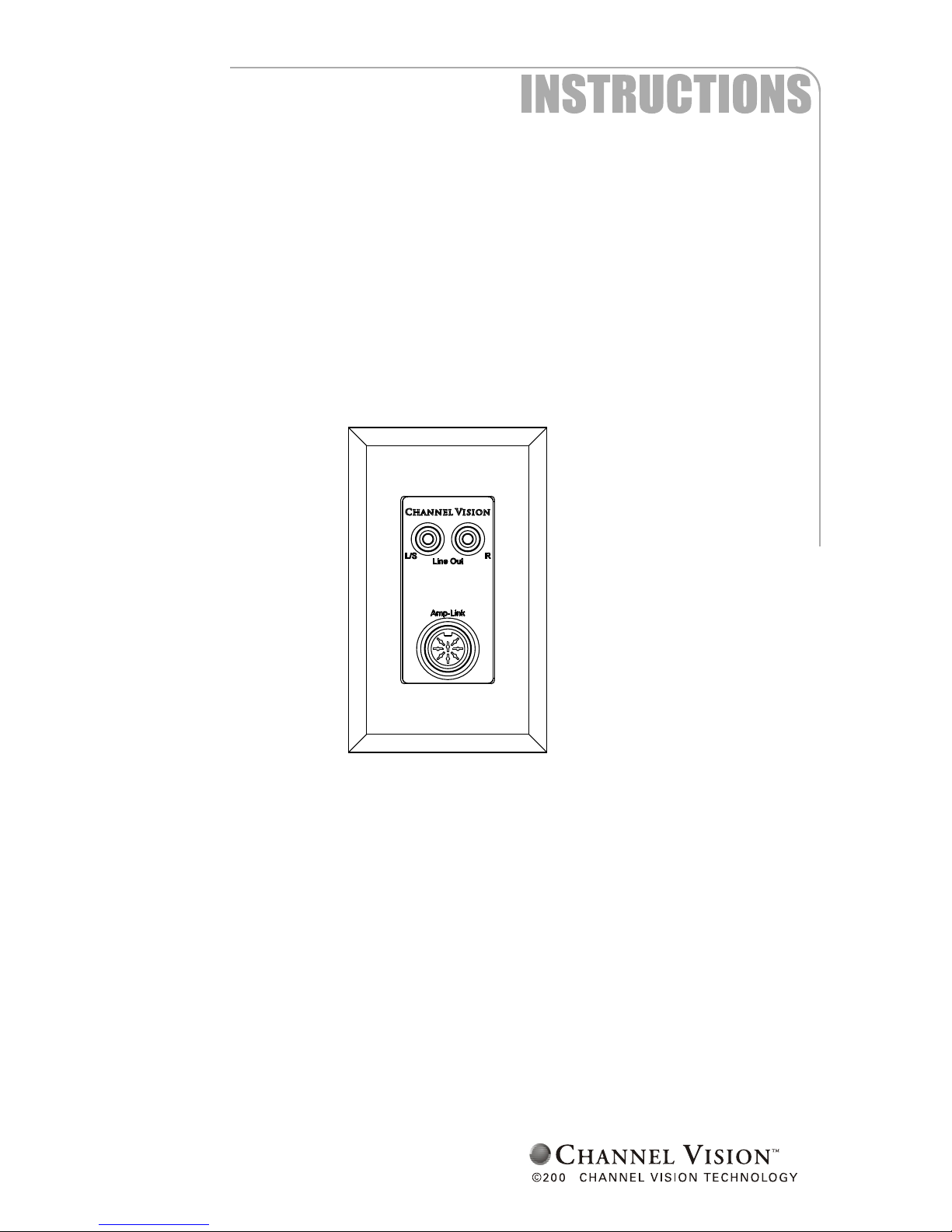
Specifications: (typical at 25 degrees C)
Maximum input power 100 Watts RMS
Nominal line out level 1.2VRMS @ max. input power
Maximum pass through power 100 Watts RMS
Frequency Range:
L/R mode 20Hz - 20kHz +/-0.5dB
Sub mode 20Hz - 150Hz +/-0.5dB (-6dB @ 200Hz)
Specifications subject to change without notice
A-BUS is a registered trademark of LeisureTech Electronics Pty Ltd

Other Channel Vision Media Converter manuals

Channel Vision B-204 User manual

Channel Vision

Channel Vision B-204 User manual

Channel Vision A0302 User manual

Channel Vision

Channel Vision A0302 User manual

Channel Vision CVT-2/4PIA-II User manual

Channel Vision

Channel Vision CVT-2/4PIA-II User manual

Popular Media Converter manuals by other brands

SIGNALCORE SC5405A Operating & programming manual

SIGNALCORE

SIGNALCORE SC5405A Operating & programming manual

Peavey MediaMatrix sWALL 2x2 quick guide

Peavey

Peavey MediaMatrix sWALL 2x2 quick guide

Harman AMX NMX-ENC-N2612S-C quick start guide

Harman

Harman AMX NMX-ENC-N2612S-C quick start guide

Carel Pc-GATE RS232 quick guide

Carel

Carel Pc-GATE RS232 quick guide

Thor Broadcast H-H.264IP-E manual

Thor Broadcast

Thor Broadcast H-H.264IP-E manual

LEVTECH LSP-CRS user manual

LEVTECH

LEVTECH LSP-CRS user manual

eks EL-1000-XSG-SFP manual

eks

eks EL-1000-XSG-SFP manual

Converters.TV 15385 Operation manual

Converters.TV

Converters.TV 15385 Operation manual

evertz 7800 manual

evertz

evertz 7800 manual

Axis AXIS Q7406 installation guide

Axis

Axis AXIS Q7406 installation guide

Converters.TV 15342 Operation manual

Converters.TV

Converters.TV 15342 Operation manual

Eurotherm 591H manual

Eurotherm

Eurotherm 591H manual

Fujitsu IP-9500e user guide

Fujitsu

Fujitsu IP-9500e user guide

Autonics SCM-US48I manual

Autonics

Autonics SCM-US48I manual

CTS CVT-2512 SERIES user guide

CTS

CTS CVT-2512 SERIES user guide

DAAB DB406 instruction manual

DAAB

DAAB DB406 instruction manual

iLive IHB617B user manual

iLive

iLive IHB617B user manual

Extron electronics Four Input Video and RGB Scaler DVS 304 user manual

Extron electronics

Extron electronics Four Input Video and RGB Scaler DVS 304 user manual

manuals.online logo
manuals.online logoBrands
  • About & Mission
  • Contact us
  • Privacy Policy
  • Terms and Conditions

Copyright 2025 Manuals.Online. All Rights Reserved.