HCS GDC D1 TECHNICAL DESCRIPTION
APRIL 2019
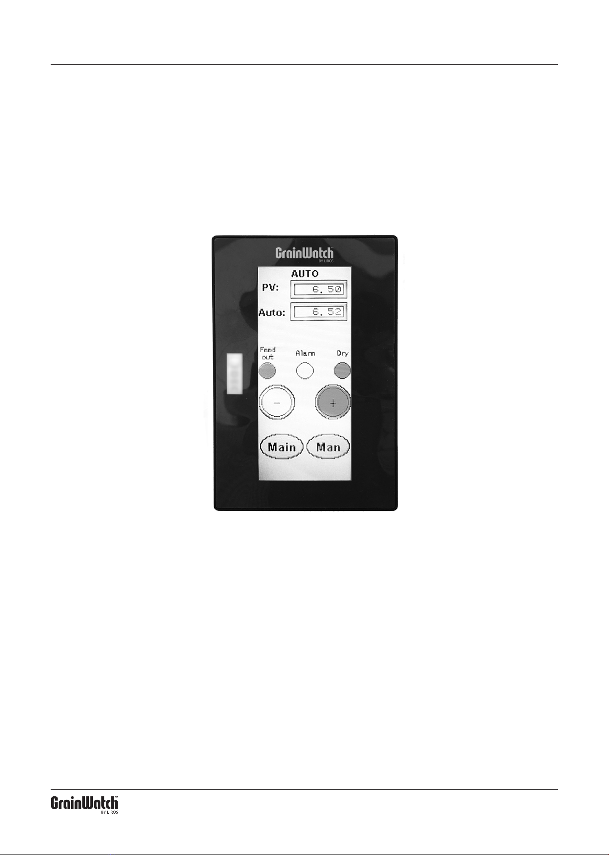
3. Auto Mode
5
With Auto mode, the control is given a value from the
transducer displayed in the “PV” box. The value is dif-
ferent for different types of cereals with the same mois-
ture content and changes according to the moisture
level of the cereals. Dry commodity = low value, wet
commodity = high value.
The Auto value setting is made either of an earlier
value used for the grain in the dryer, or from the “Auto-
Set” in a previous manual run (see chapter 2).
If, when checked, the water content is not the de-
sired, the autovalue can be changed with the plus and
minus buttons (Plus = higher value, wetter commodity,
Minus= lower value, drier commodity). However, never
change the autovalue more than 0.20 at a time.
After resetting values, let the dryer go for at least one
hour. Then check that the adjustments support the
desired result.
Normally, the Auto value should be between 5.00-
8.00 – Lowest value for dry commodity (oil seeds) or
commodity with a lot of shell (oats). Highest value for
wet commodity with little shell (wheat).
Feed Auto is lit when output is active. The output
time is normally 27 secs but it can be changed to 18
secs to get closer feedouts with less content each time.
Alarms are activated when the equipment has
made 6 feedouts on the longest drying time without
lowering the water content. When alarms are activated,
no further ejections are made.
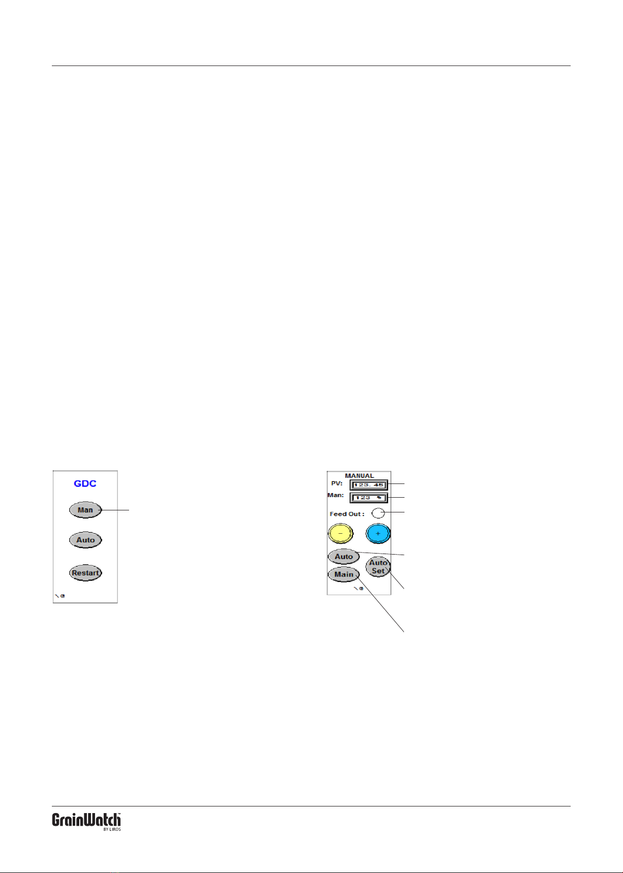
Press “Auto”
Step 1
PV: Shows the signal from the sensor.
Man: Shows the percentage set.
Feed Out: Lights up yellow when output is
active.
–: Decreases the set percentage (drier item).
+: Increases the set percentage (wetter item).
Dry: Lights up Green when the commodity is
drier than the set value.
Alarm: Red light when alarm is activated.
Man: To go to Manual mode.
Main: To go to Home screen.
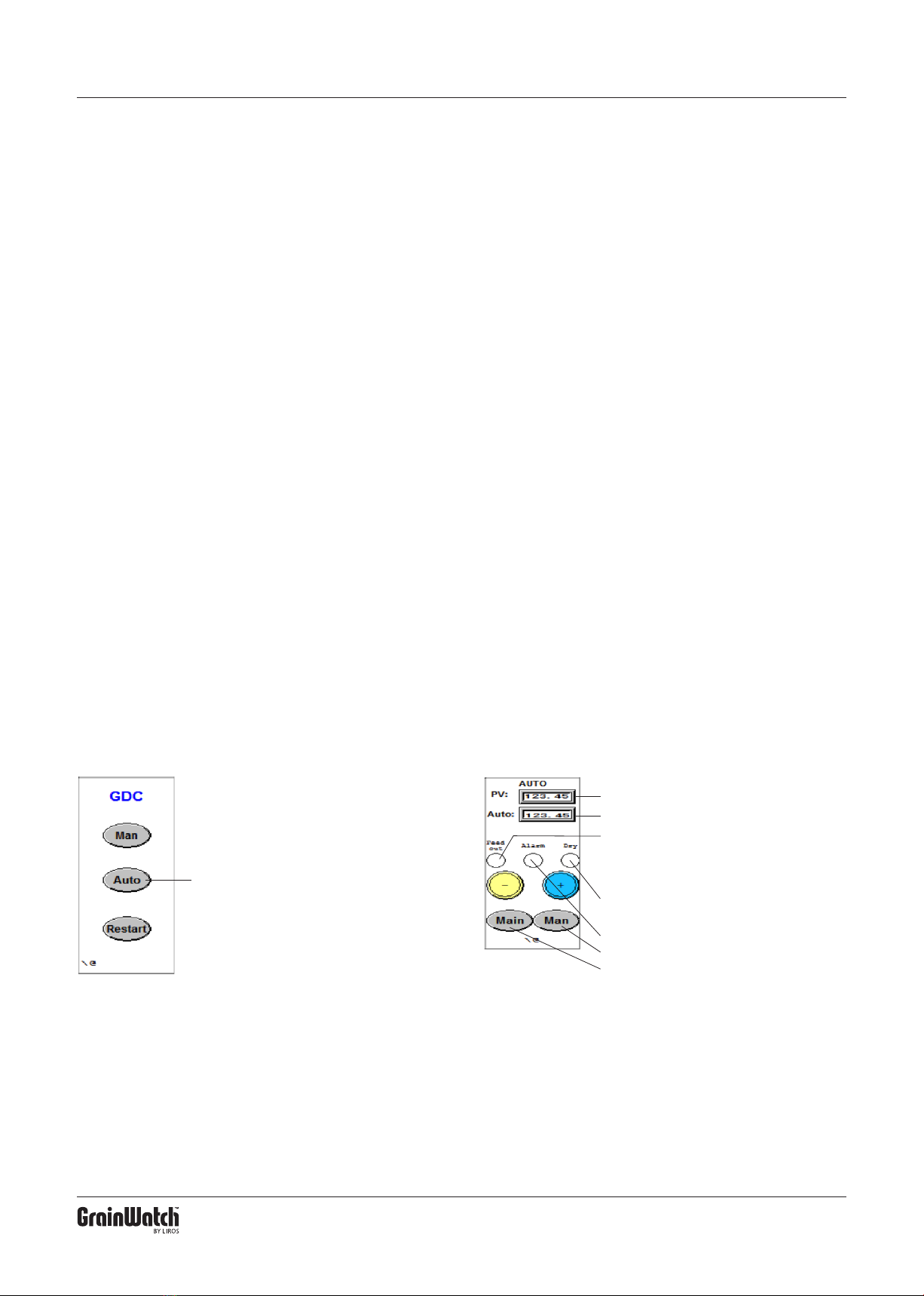
Step 2