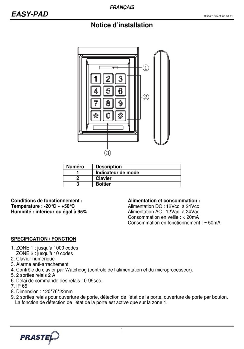
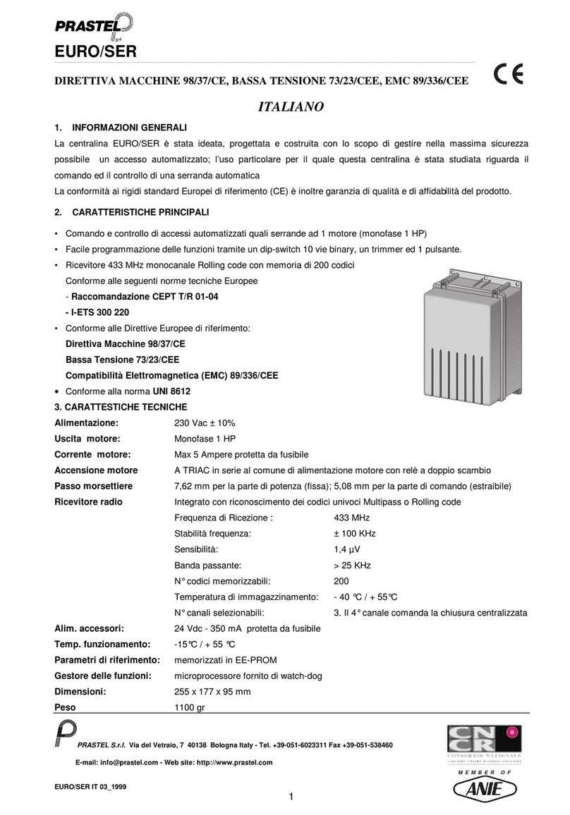
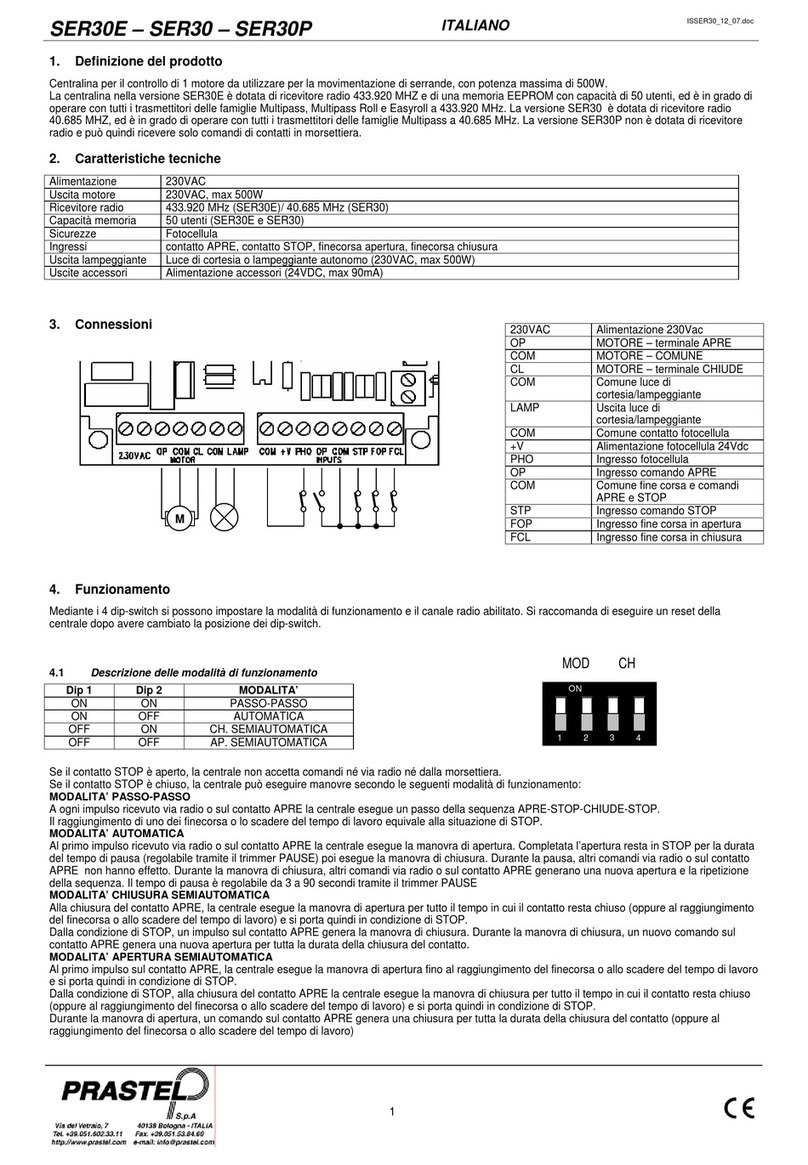
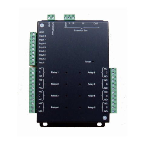
PRASTEL UNIK3I-V4 Safety guide

UNIK3I-V4 CONTROL UNIT
Programmable control board for sliding gates
with inverter technology
Manual for installation
WARNING!! DELTA CONNECTION OF THE MOTOR IS REQUIRED

ITA ENG FRA ESP
2 / 12
6-1622613 rev.2 14/01/2019
WARNING: DO NOT INSTALL THE CONTROL UNIT WITHOUT READING THE INSTRUCTIONS FIRST!
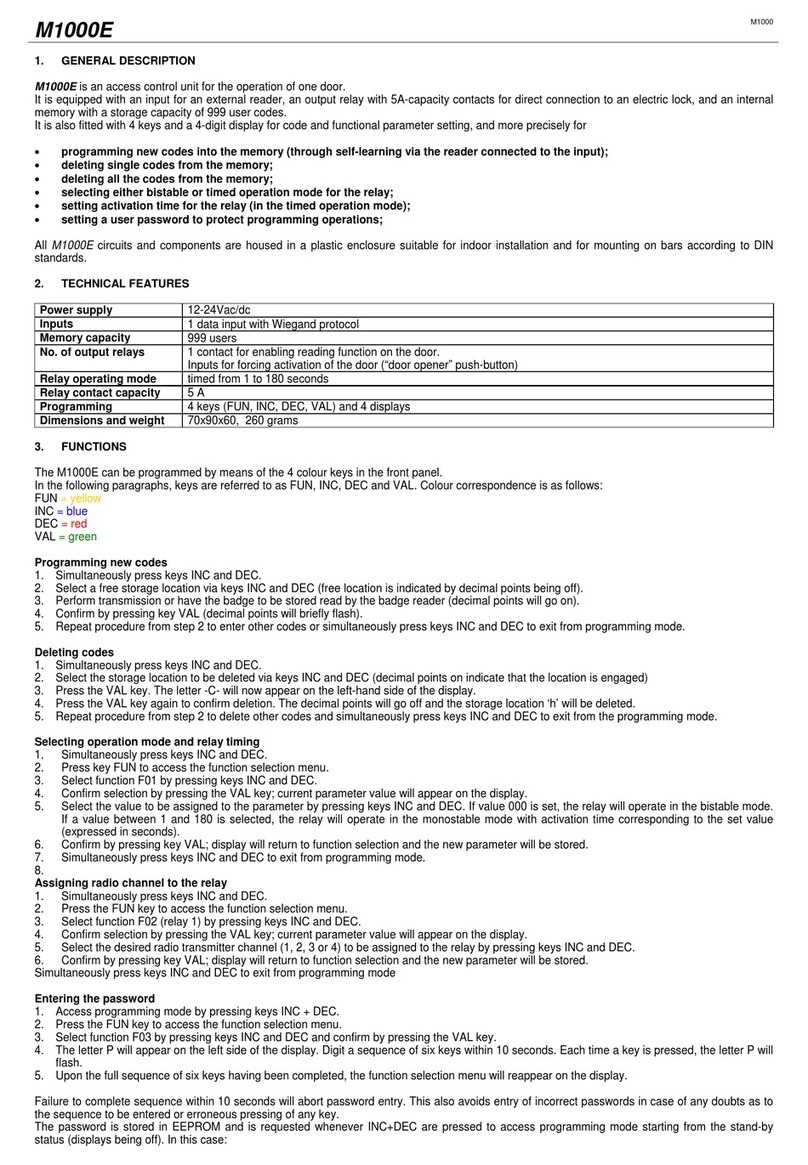
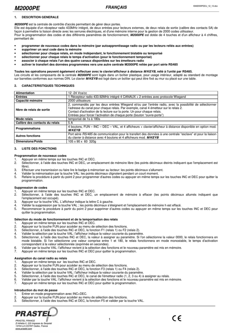
The Three-phase control unit UNIK3I-V4 three-phase is a device suitable for operating and controlling the sliding gate in a way easy and complete; it is
designed in order to satisfy all possible needs.
The inverter on board allows to set the maximum torque limits along with the possibility to modify the frequency (the speed of the motor).
The possibility to use motors with encoder allows the unit to detect possible obstacles along the run and reverse its direction of motion. It is suitable to
command and control automatics accesses equipped with three-phase motors 230/400Vac delta-connected max 1,5KW (current limited to 10A). Every
control board is equipped with a memory module that stores all personal settings and parameters needed for operating the control board (these data
can be transferred from one unit to another one). It is equipped with inputs for self-tested photocells, keys for SS (step-by-step), PED (partial opening),
OPEN and CLOSE, switch limits, security stops and a wide display with 3 keys for settings. It is also equipped with a molex connector for a plug-in
receiver, output for courtesy and flashing light. It is possible to connect an additional card (R1) to operate an electric lock.
1. Introduction
It is FUNDAMENTAL to connect the motor and the unit to the EARTH in order to operate the control unit correctly!
In case an encoder is applied, it is compulsory to use a shielded cable with the screening connected to the
EARTH only by one end of the cable itself.
WARNING!! DELTA CONNECTION OF THE MOTOR IS REQUIRED.
NOTE: EDGE, PHOTO and STOP inputs, normally closed contact (NC), if not used, they must be excluded
through the using of the dip switch. Move to ON the dip of the unused input.
ATTENTION: Before activating the installation, make sure that the installed safety devices are functioning
properly.
For the connection of the motor we recommend to use a screened cables 3 poles + earth 1.5 mm2 (type FD781CY).
For the connection of the possible encoder we recommend to use a screened cable 3 x 0,75mm2 (type OLFLEX-110CH).
OUT External brake or electric lock
COURTESY LIGHT Courtesy light
FLASH Flashing light
POWER SUPPLY Power supply
PE Ground
MOTOR Motor
24VAC Auxiliary power supply (24Vac)
24VDC PHOTO Photocell power supply (24Vdc)
EDGE Safety edge
PHOTO Photocell
LSC Closing limit switch
LSO Opening limit switch
STOP Stop
OPEN Opening command
CLOSE Closing command
PED Partial command
SS Step by Step command
ENCODER Encoder
ANTENNA Antenna
POWER ON Power supply LED
INPUTS LED Input LEDs
DISPLAY Display
MEMORY Memory
RADIO RECEIVER Radio receiver
Fuse:
F1: 230V line protection.
F2: inputs protection.
F3: photocells protection.
F4: 24Vac auxiliary protec-
tion.
Fuse features:
F1: T 10A
F2: F 250mA
F3: F 250mA
F4: F 500mA
WARNING: Be sure that the limit switches are connected and correctly adjusted.
NOTE: to use the obstacle sensitivity function, it is necessary to install a compatible Encoder.

ITA ENG FRA ESP
3 / 12
6-1622613 rev.2 14/01/2019
2. Electrical connections
1
PHOTOCELL INPUT
Connect the NORMALLY CLOSED contact
of the photocell (PHOTO) between the clamps
22 and 30 of the terminal board.
ATTENTION: if not used set the PHOTO dip
switch ON.
The functioning of the photocells can be modified in
the MENU A.
SAFETY EDGE INPUT
Connect the contact NORMALLY CLOSED of
the SAFETY EDGE between the clamps 21 and
30 of the terminal board.
ATTENTION: if not used set the EDGE dip
switch ON.
OUTPUT ELECTRIC BRAKE / ELECTRIC
LOCK
Connect the ELECTRIC BRAKE / ELECTRIC
LOCK between the clamps 1 and 2, if you need
a NORMALLY CLOSED dry contact (16A MAX).
Connect the ELECTRIC BRAKE / ELECTRIC LOCK
between the clamps 2 and 3, if you need a
NORMALLY OPEN dry contact (16A MAX).
2
COURTESY LIGHT
Connect the courtesy light to the clamps 4 and
5, 230Vac 100W MAX.
It is possible to light up the action area of the
automatism during each motion.
The functioning of the auxiliary light is controlled by
the MENU A.
3
FLASHING LIGHT
Connect the flashing light to the clamps 6 and 7. Use a flashing light without self flashing card
230Vac 60W MAX.
4
POWER SUPPLY
Connect the power supply cable to the clamps 8
and 9.
Use a cable with correct section according to the
current absorbed by the motor.
Do not connect the card directly to the electric
network. Put a device which can ensure the
disconnection of each pole from the power supply of
the control unit.
GROUND
Connect the ground to one of the clamps PE 10,
11 or 12.
5
6
MOTOR OUTPUT
Connect the phases of the motor to the clamps
13, 14 and 15.
ATTENTION !! THE MOTOR SHOULD BE
DELTA CONNECTED.
Before activating the automation make sure that all
the safey devices are correctly cabled and
functioning, refer to the preliminary checkings
section of chap.4
!! Risk of electric shock !!
For the connection of the motor we
recommend to use a screened cables 3
poles + earth 1.5 mm2 (type FD781CY).
7
ACCESSORIES OUTPUT
Accessories output 24Vac 10W.
8
PHOTOCELLS POWER SUPPLY
Connect the clamp 18 of the control unit to the
clamp + of the power supply of the photocells
receiver.
Connect the clamp 19 of the control unit to the
power supply clamp - of the photocells receiver
and of the transmitter.
Connect the clamp 20 of the control unit to the
power supply clamp + of the trasnmitter of the
photocells.
The photocells test test is activated by the MENU A.
ATTENTION: the control unit gives a voltage of
24 Vdc and can supply a maximum power of 5W.
For the safety edges test connect the test device of
the safety edge on the power supply pins of the TX
(test activated wiht low logic signal 0Vdc).
Please refer to the manual of the safety edge.
9
10
The functioning of the safety edge can be modified
in the MENU A.

ITA ENG FRA ESP
4 / 12
6-1622613 rev.2 14/01/2019
14
17
15
16
18
ANTENNA INPUT
Connect the signal cable of the antenna to the
clamp 34 of the terminal board.
Connect the ground of the antenna to the clamp
35 of the terminal board.
The presence of the metallic parts or humidity in the
walls could have negative influences on the range of
the system. We suggest therefore to not place the
receiving antenna and/or transmitters near big
metallic objects, near the floor or on the ground.
STEP BY STEP INPUT
Connect the STEP-BY-STEP button between
the clamps 29 and 30.
ATTENTION: leave it open if not used.
Under the dead man mode the STEP BY STEP
button operates as OPEN.
STOP INPUT
Connect the contact NORMALLY CLOSED of
the STOP between the clamps 25 and 30 of the
terminal board.
ATTENTION: if not used set the STOP dip switch
ON.
INPUT CLOSING LIMIT SWITCH
Connect the contact NORMALLY CLOSED of
the CLOSING LIMIT SWITCH (LSC) between
the clamps 23 and 30 of the control board.
Before activating the installation make sure that the
limit switches are functioning and correctly cabled.
INPUT OPENING LIMIT SWITCH
Connect the contact NORMALLY CLOSED of
the OPENING LIMIT SWITCH (LSO) between
the clamps 24 and 30 of the terminal board.
Before activating the installation make sure that the
limit switches are functioning and correctly cabled.
PARTIAL INPUT
Connect the PARTIAL button between the
clamps 28 and 30 of the terminal board.
ATTENTION: leave it open if not used.
Under the dead man mode the PARTIAL button
operates as CLOSE.
OPEN INPUT
Connect the OPEN button between the clamps
26 and 30 of the terminal board.
ATTENTION: leave it open if not used.
CLOSE INPUT
Connect the CLOSE button between the clamps
27 and 30 of the terminal board.
ATTENTION: leave it open if not used.
ENCODER INPUT
Connect the SIGNAL cable of the encoder to the
clamp 31 of the terminal board.
Connect the GND cable of the encoder to the
clamp 32 of the terminal board.
Connect the cable +Vdc of the encoder to the
clamp 33 of the terminal board.
ATTENTION: leave it open if not used.
The activation / desactivation of the encoder function
is controlled in the MENU A.
For the connection of the possible encoder we
recommend to use a screened cable 3x0,75mm2
(type OLFLEX-110CH).
11
12
13
19

ITA ENG FRA ESP
5 / 12
6-1622613 rev.2 14/01/2019
3 Programming Menu
This procedure must be carried out ONLY by the installer and ONLY during the installation of the system.
WARNING: the motor must be still, preferably in closed position, in order to access the programming menu!
8888888888888888
8888888888888888
3.1 Activation and selection of the programming menu
The control unit UNIK3I-V4 is equipped with THREE user menus (MENU A, MENU B, MENU C), by which it is possible to regulate, program and
modify all functional parameters. Follow the indications on the display during the programming phases.
MENU A - allows to activate the optional functions and to select the intervention modalities of the security systems.
MENU B - it is dedicated to the learning of the runs, to the operations related to the manual movement and to the regulation of the control
parameters of the motor.
MENU C - menu for auxiliary configurations for user’s support.
2
1Stop the motor and get in safety conditions. The display must not show any indications.
The display shows the
first entry available.
Select an entry of the menu (see following table); shortly press key
P3 to scroll down to the following index, or key P1 to go back to
the previous menu.
3The display shows the entry selected.
Some parts of the control unit are subject to dangerous voltages!
Pay attention during the phase of manual accessing to the control board.
4Confirm the entry selected by pressing key P2.
The first line of the display shows the present setting for
the function selected.
The second line of the display shows the possible
modification settings according to the parameter
selected (see specific paragraphs).
5Modify the status of the parameter by following the
indications written in the second line of the display by using
keys P1 e P3.
The first line of the display shows the present setting for
the function selected.
The second line of the display shows the possible
modification settings according to the parameter
selected (see specific paragraphs).
6Confirm the setting selected by pressing key P2. The display indicates the correct storage of data and then
shows the entry selected.
7It is possible to modify other parameters (go back to point 3) or to
exit the programming menu by selecting the option EXIT
(confirm by pressing key P2).
Exit from the menu is confirmed by the absence of
indications on the display.
AUTOMATIC EXIT FROM THE MENU: the menu exits automatically in case of long inactivity (longer than 15 seconds).
8888888888888888
8888888888888888
8888888888888888
8888888888888888
Press and keep pressed key P1 for 2 seconds in order to
activate MENU A.
Press and keep pressed key P2 for 2 seconds in order to
activate MENU B.
Press and keep pressed key P3 for 2 seconds in order to
activate MENU C.
LANGUAGE SETTING
Press key P3 for 2 seconds. Confirm with key P2. Select the language by pressing either P1 or P3.
Confirm with key P2.
It is suggested to select the language before any other operations.

ITA ENG FRA ESP
6 / 12
6-1622613 rev.2 14/01/2019
3.2 Programming menu A (key P1)- List of parameters
The following table lists the entries of menu A and reports a short description of the parameters that can be adjusted; refer to paragraph ADVANCED
FUNCTIONS for more details.
Auto
ReclosingTim
Timed closure of the gate (only from total or partial opening).
OFF: disabled.
HH:MM:SS: time of persistence in opening position.
PhotoAuto
Reclose
Immediate closing after the intervention of the photocell (only from total or partial opening).
OFF: disabled.
ON: the gate closes 3 seconds after the contact between photocell has restored.
Brake
Brake operation (for motors with high inertia).
OFF: disabled.
1: electronic brake.
2: activation of the contact for an external electric brake, active with still motor.
3: activation of the contact for an external electric brake, active when motor is moving.
Dead Man
“Dead Man” mode. The motor moves only by means of a permanent command.
OFF: disabled.
ON: enabled (WARNING: automatic motions are disabled).
Condominium
Condominium function. The commands SS and PED allow only the opening of the gate.
OFF: disabled.
ON: enabled (WARNING: enable the “Automatic Re-Closure” in order to close).
Photo Inv
Photocell intervention modality.
OFF: the gate stays still until the obstacle is removed, and then opens completely.
ON: the gate opens completely (this function does not apply in opening).
Photo Test
Functional test of the photocell; it is executed before the gate moves.
OFF: disabled.
ON: test activated (WARNING: supply the photocell with power as shown in the scheme).
Edge Inv
Modality of operation of the safety edge (sensible edge).
OFF: the gate stops.
ON: the gate opens completely (this function does not apply in opening).
Edge Test
Functional test of the safety edge; it is executed before the gate moves.
OFF: disabled.
ON: test activated (WARNING: supply the safety edge with power as specified in the chap. 2.8).
Pre-Blink
Short flash before the motion of the gate.
OFF: disabled.
ON: enabled.
Area light
Modality of functioning of the auxiliary output for lighting.
OFF: courtesy light.
ON: zone light (lit-off only when the gate is completely closed).
Aux Light Time
Auxiliary light’s switching-off delay for lighting.
OFF: Auxiliary light’s output disabled.
HH:MM:SS: switching-off delay - auxiliary light’s output enabled.
Clock
Programmed opening function.
OFF: disabled.
ON: the gate opens and stays open until the OPEN input is active.
Water Hammer
OP
Water hammer before the gate opens.
OFF: disabled.
XX,Xs: enabled. Adjustment of pressure time (in seconds) applied to the mechanical stop in closing.
Encoder
Functioning with encoder (only for motors equipped with a suitable encoder).
OFF: disabled.
ON: enabled (WARNING: the re-programming of the runs is needed).
Sensor level
Level of operation of the “motor still sensor” (with active encoder only).
OFF: sensor disabled.
NNN : sensor enabled - adjustment of operation’s sensitivity.
Sensor Inv
Modality of operation of the “motor still sensor” (with active encoder only).
OFF: the gate stops.
ON : reverses shortly in opening; opens completely in closing.
EXIT
MENU A

ITA ENG FRA ESP
7 / 12
6-1622613 rev.2 14/01/2019
3.3 Programming menu B (key P2) - List of parameters
The following table lists the entries of menu A and reports a short description of the parameters that can be adjusted; refer to paragraphs dedicated to
each function for more information.
Manual Motion
Allows to move the gate at low speed by using the keys located on the control board.
This function is fundamental in order to check the motion during the installation.
End position
Learning the full run of the gate, both in opening and in closing.
WARNING: this operation must start when the gate is completely closed.
Ped. Position
Learning of the opening partial run.
WARNING: this operation must start when the gate is completely closed.
High Speed OP
Regulation of the normal speed of the gate during the opening phase.
NNN: speed expressed in Hz (frequency of the wave supplied to the motor).
Low Speed OP
Regulation of the speed of the gate during the opening phase when approaching the end of the run.
NNN: speed expressed in Hz (frequency of the wave supplied to the motor).
High Speed CL
Regulation of the normal speed of the gate during the closing phase.
NNN: speed expressed in Hz (frequency of the wave supplied to the motor).
Low Speed CL
Regulation of the speed of the gate during the closing phase when approaching the end of the run.
NNN: speed expressed in Hz (frequency of the wave supplied to the motor).
High Torque OP
Torque supplied to the motor during the opening phase at normal speed.
NNN: percentage of torque supplied to the motor.
Low Torque OP
Torque supplied to the motor during the opening phase when approaching the end of the run.
NNN: percentage of torque supplied to the motor.
High Torque CL
Torque supplied to the motor during the closing phase at normal speed.
NNN: percentage of torque supplied to the motor.
Low Torque CL
Torque supplied to the motor during the closing phase when approaching the end of the run.
NNN: percentage of torque supplied to the motor.
EXIT
MENU B
3.4 Programming menu C (key P3) - List of parameters
The following table lists the entries of menu A and reports a short description of the parameters that can be adjusted; refer to paragraphs dedicated to
each function for more information.
Language
Select the language (where applicable).
Backlight
Backlighting of the display.
OFF: the light of the display is disabled.
ON: the light of the display is enabled and its automatic switching-off is timed (Energy saving).
Reset
Total reset of factory settings of the control board.
WARNING: all programming operations and the setting of the control board must be repeated after this
operation.
EXIT
MENU C

ITA ENG FRA ESP
8 / 12
6-1622613 rev.2 14/01/2019
4. Preliminary checks
6
Manually bring the gate to a total opening position and
check the status of led LSC.
Once all above operations are successfully terminated, close
the automation and lock the motor.
2
1
The preliminary checks must be carried out only by professionals and by paying maximum attention. The correct wiring of the motor and the limit
switches is very important for the correct functioning of the automation.
Unlock the motor and supply the system with power only
after controlling the wiring connections and checking the
absence of short circuits.
Check the status of the LEDs input by considering that all
normally closed (NC) inputs must have their corresponding
led alighted.
Led LSC is off. Correct functioning
Led LSC is on, but led LSC is off; check the connection
of the limit switches.
Manually bring the gate to a total closing position and
check the status of led LSC.
3
Led LSC is off. Correct functioning.
Led LSC is on, but led LSC is off; check the connection
of the limit switches.
Manually bring the gate to the middle of the run and then
lock the motor.
Enter the parameter Manual Movement of MENU B and
command the closure of the gate.
WARNING: pay attention with the moving gate!
4
The motor starts to move. Watch its sense of rotation:
If the gate opens, then stop the manual motion,
disconnect the system from the power and reverse the
motor connections. Then try again.
If the gate closes, then stop the manual motion and go to
the following phase
Enter the parameter Manual Movement of MENU B and
command the opening of the gate.
WARNING: pay attention with the moving gate!
5
The motor starts to move. Watch its sense of rotation:
If the gate closes, then stop the manual motion,
disconnect the system from the power and reverse the
motor connections. Then try again.
If the gate opens, then stop the manual motion and go to
the following phase
5. Manual motion (Menu B - Manual movement)
This operation must be carried-out only by qualified personnel and by paying maximum attention.
The manual motion is an operation planned only for the phase of installation; it allows to move the gate at a limited speed in both directions.
WARNING: the photocells and the safety edge are not monitored during this phase!
Access to parameter Manual Mov. of MENU
B and confirm by pressing key P2. Move the gate by using keys P1 and P3.
Press key P2 or wait 15 sec. in order to exit the menu.
6. Learning
Learning the run allows to define the parameters of the run of the gate, such as the width of the run at normal speed and at slowed speed.
Check that the adjustment of the torque and the speed of the gate are set before carrying out the learning phase.
Check that the gate is closed before starting the learning phase.
Be sure that the limit switches are connected and correctly adjusted.
6.1 Learning the run of the gate (Menu B - Final position)
Enter the parameter Final Position of MENU
B and confirm by pushing key P2.
Start moving the gate by pressing and releasing key P1 (START) or a Step-
by-Step key.
Push key P1 (START) or a Step-by-Step key when the gate reaches the
point where you want to start the slowdown in the opening phase.
The gate continues its run at reduced speed as far as it hits the opening
limit.
Once the opening limit has been reached, the gate starts to close.
Push key P1 (START) or a Step-by-Step key when the gate reaches the
point where you want to start the slowdown in the closing phase.
The gate continues its run at reduced speed as far as it hits the closing limit.
The programming is terminated once the closing limit is reached.
Note: in case no slowdown zones are set, then the control unit follows the
factory settings.
Exit the menu by scrolling the entries until you
find EXIT.
WARNING! Before executing the learning of the strokes, it is advisable to disable the safety devices by means of dip
switches, by moving them to the ON position. This avoids involuntary interventions of the safety devices during the
learning phases.

ITA ENG FRA ESP
9 / 12
6-1622613 rev.2 14/01/2019
Enter the parameter Ped. Position of MENU
B and confirm by pressing key P2.
Start moving the gate by pressing and releasing key P1 (START) or a
Step-by-Step key.
When the gate reaches the position of partial opening, then push key
P1 (START) or a step-by-step key.
The gate moves again in closing.
When the gate hits the limit in closing, then the programming is
terminated.
Exit the menu by scrolling the entries until you
find EXIT.
6.2 Learning the partial run (Menu B – Ped. Position)
Learning the partial run allows to define the position of partial opening that allows the partials accessing (PED command).
Check that the adjustment of the torque and the speed of the gate are set before carrying out the learning phase.
Check that the gate is closed before starting the learning phase.
Be sure that the limit switches are connected and correctly adjusted.
The entries of menu B - Speed and torque - once the parameters themselves are entered allow to adjust the corresponding parameters from a
minimum up to a maximum value, according to the indications shown on the display.
The versatility of the control board allows an infinity of possible combinations: however it is recommended to adjust the settings by keeping into
account the dimensions and weight of the gate. High speeds may be dangerous, as well as high torques.
Such regulations must be carried out only by professionals.
It is recommended to check the correct functioning of the automation after any regulation.
It is highly recommended to learn the runs of the gate each time these parameters are changed.
8. Advanced functions
Photocell test
This control unit is equipped with a function which allows to control the proper functioning of photocells before any operation of the motor is made.
The security of the system is therefore higher in case the photo-device breaks down (for example, if the relay of exit is stuck) or there is a
undesired short circuit on the input of the photocells. The control board indicates a possible fault by flashing only once when any key is pressed
and also by not moving at all. This check is made after the control board receives a command to move, but before the control board itself gives
power to the motor.
Edge Test
Functional test of the safety edge. Connect the safety edge as shown in the instructions by using the photocell test’s clamp.
Condominium
All commands given via radio or by a step-by-step and/or a partial keys involve only the opening of the gate. The closing is related to the function
of automatic closing, which MUST BE ABSOLUTELY ACTIVATED since every command of closing is ignored.
PhotoAutoReclose
The gate closes 3 seconds after the photocell intervenes in case the gate is in a totally open or in a partial open position.
These are functions and/or functional modalities that can be activated by the user through the programming menu.
Automatic closing
Timed closing of the gate from totally open position or partial opening position. The “stop” command disables the automatic closing until a new
command given by the user is received (SS, CLOSE, etc).
Motor brake
To be used with motors with a strong inertia and the necessity to quickly stop the automation. Pay attention as the mechanics must be sized
accordingly.
OFF: Brake disabled.
1: Electronic braking function.
2: Activation of the contact for an external electric brake, active with still motor.
3: Activation of the contact for an external electric brake, active when motor is moving.
Dead Man
The motor moves only with permanent a command and not with just impulses: the motor opens if the key “open” is kept pressed, and the opposite
operation applies with the key “close”. WARNING: this modality forbids all operations of automatic motion!
Inv. On photocells
Allows to set if, once the photocell beam is interrupted, the gate must reverse immediately (only in closing) or just after the removal of the obstacle
(it applies both in opening and in closing).
Edge Inv.
Allows to set if, once the safety edge alarms itself, the gate must stop or it must stop and then reverse (applies only in the phase of closing).
7 Adjustment of the speed and the torque (Menu B - Speed and torque)
WARNING! Before executing the learning of the strokes, it is advisable to disable the safety devices by means of dip
switches, by moving them to the ON position. This avoids involuntary interventions of the safety devices during the
learning phases.

ITA ENG FRA ESP
10 / 12
6-1622613 rev.2 14/01/2019
Reset of the unit according to the display indications; this reset the control board to its factory settings.
WARNING: all programming and personal settings must be repeated after the reset of the control board!
Clock function
Input OPEN becomes input clock in case it is possible to connect a timer for the programmed opening of the automation. The contact is
understood as a command to opening and to stay open as long as this status stays closed. When the contact is opened, then the unit reset its
normal functioning, waiting for a command given by the user (if the automatic closing is required, then it must be enabled from the menu).
Pre-flashing
This function commands a blinking BEFORE each movement in order to indicate the imminent movement itself.
Zone light
There is the possibility to use the auxiliary output as a courtesy light or as a light zone (always lit-on as long as the gate is open).
Auxiliary light timeout
There is the possibility to set the delay of switching-off of the auxiliary light after the automation stops.
Water hammer in opening
If the automation is equipped with an electronic lock, then it is advisable that, when the gate is closed, the motor shortly operates in closing before
it starts the opening phase (water hammer). This function allows to unlock the electronic lock in any case, even when the weather conditions are
very bad (for example in case of ice). The activation of this function enables also the electronic lock’s output.
Sensor level
If it is enabled, it allows to modify the intervention sensitivity of the “stop motor” sensor. Decrease the value that is set in order to have higher
sensitivity. If the sensitivity is too high and the sensor operates without any apparent reason, then increase the value.
Encoder
If the motor is equipped with a suitable encoder, then it is possible to enable the functionalities of the encoder. In such way the control board does
not work any longer “by time” but “with encoder” instead. It is possible to detect the possible blocking of the motor.
Sensor inversion
Allows to define the reaction of the gate in case the “stop motor” sensor applies. If the reversing is not activated, then the gate stops and waits for
a new command. If the reversing is activated, then the gate reverses shortly in case the sensor applies during the opening; it open completely in
case the sensor applies during the closing phase of the gate.
10 Backlighting of the display (Menu C - Display light)
Enter MENU C and follow the instructions shown on the display in order to enable/disable the backlighting of the display itself.
The control board operates the function Energy saving which automatically switches off the display after the unit is inactive since some minutes.
The backlighting is automatically reactivated (if this function is enabled) when the user operates on the control board.
11 Housing for radio receiver
The unit disposes of a molex connector to house an radio receiver. The first channel of the receiver is associated to the wired command SS,
whereas the second radio-channel (if it is present) is associated to wired command PED.
Follow the instructions of the receiver itself for learning the transmitters.
9 RESET of the control board (Menu C - Reset)
The functioning of the output depends on the setting of the parameter “Brake”:
Parameter “Brake” OFF-1: A dry contact (without voltage) is available on the output for the activation of the electric lock. The electronic lock can
be activated by previously enabling the Water Hammer in opening (parameter Water Hammer OP).
Parameter “Brake” 2-3: A dry contact (without voltage) is available on the output for the activation of an electric brake.
12 ELECTRIC BRAKE or ELECTRIC LOCK output

ITA ENG FRA ESP
11 / 12
6-1622613 rev.2 14/01/2019
9 Tips for a successful installation
9.1 High speed movements
9.3 Correct working
The correct setting of parameter is when you are not able to stop the automation when trying counteracting the movement.
The use of safety devices is absolutely necessary to ensure the safety of the automation.
PROBLEM SOLUTION
The motor stops for the effort during the movements.
It is easy to stop the automation during the movements
counteracting the movement.
The gate moves slowly despite having set an high speed.
Raise the torque supplied to the motor until problem is solved.
High Torque OP, High Torque OP.
Lower the speed of the motor until problem is solved.
High Speed OP, High Speed CL.
The motor stops and the control unit shows FAULT on the
display or 10 seconds of fast blinking.
Lower the torque supplied to the motor until problem is solved.
High Torque OP, High Torque OP.
Lower the speed of the motor until problem is solved.
High Speed OP, High Speed CL.
9.2 Low speed movements (slowing down)
PROBLEM SOLUTION
The motor stops for the effort during the movements.
It is easy to stop the automation during the movements
counteracting the movement.
The gate moves slowly despite having set an high speed.
Raise the torque supplied to the motor until problem is solved.
Low Torque OP, Low Torque CL.
Lower the speed of the motor until problem is solved.
Low Speed OP, Low Speed CL.

ITA ENG FRA ESP
12 / 12
6-1622613 rev.2 14/01/2019
WARNING AND ADVICES
Avoid putting the connection cables of buttons, security devices and inputs close to those of the power supply of the control unit and of the motor.
Some parts of the control unit are subject to dangerous voltage. The control unit must be installed and programmed only by qualified professionals.
Always use a device that ensures the disconnection of all poles of the control unit’s power supply.
This device can be a switch (connected directly to the power supply terminals) with a contact’s minimum distance of 3 mm for each pole, or it can be a
device connected to the power network.
For connecting the card and the motors we recommend to use cables with double isolation as in compliance to the laws in force; the minimum cross
section of the single conductor must not be less than 1,5 mm² and not more than 2.5mm².
TECHNICAL FEATURES - UNIK3I-V4
Power supply 230 Vac +15%, -15% ; 50Hz single-phase
Photocells power supply 24 Vdc 5W MAX
Accessories power supply 24Vac 10W MAX
Motor output 230Vac Three-phase 1,5KW (current limited to 10A) MAX cos > 0.8
Flashing light output 230 Vac 60W MAX for fixed light, without self-blinking.
Courtesy light output 230Vac 100W MAX
Electric brake or electric lock output 250Vac 16A Max, 24Vdc 16A Max
WARRANTY - In compliance with legislation, the manufacturer’s warranty is valid from the date stamped on the product and is restricted to the repair
or free replacement of the parts accepted by the manufacturer as being defective due to poor quality materials or manufacturing defects. The warranty
does not cover damage or defects caused by external agents, faulty maintenance, overloading, natural wear and tear, choice of incorrect product,
assembly errors, or any other cause not imputable to the manufacturer. Products that have been misused will not be guaranteed or repaired.
Printed specifications are only indicative. The manufacturer does not accept any responsibility for range reductions or malfunctions caused by
environmental interference. The manufacturer’s responsibility for damage caused to persons resulting from accidents of any nature caused by our
defective products, are only those responsibilities that come under European law.
PRASTEL France
ZI ATHELIA 2
225 IMPASSE DU SERPOLET
13704 LA CIOTAT CEDEX
Tél. +33(0)442980606
Fax +33(0)442045351
Disposal of the product
This product is an integral part of the automation, and therefore, they must be disposed of together. As for the installation operations, at the end of the
life of this product, the dismantling operations must be performed by qualified personnel. This product is made from different types of materials: some
can be recycled, others must be disposed of. Please inform yourselves on the recycling or disposal systems provided for by the laws in force in your
area, for this category of product.
CAUTION! – some parts of the product can contain polluting or dangerous substances which, if dispersed in the environment, may cause
serious harm to the environment and human health.
As indicated by the symbol at the side, it is forbidden to throw this product into domestic refuse. Therefore, follow the “separated collection”
instructions for disposal, according to the methods provided for by local regulations in force, or redeliver the product to the retailer at the
moment of purchase of a new, equivalent product.
CAUTION! – the regulations in force at local level may envisage heavy sanctions in case of abusive disposal of this product.
Table of contents
Other PRASTEL Control Unit manuals

PRASTEL
PRASTEL GT+ User manual

PRASTEL
PRASTEL UNIK1E User manual

PRASTEL
PRASTEL DOM1-L1SIM User manual

PRASTEL
PRASTEL MT15000/EXT-IO Owner's manual

PRASTEL
PRASTEL MT15000/2 Owner's manual

PRASTEL
PRASTEL CNCR EURO/SER User manual

PRASTEL
PRASTEL M1000 User manual

PRASTEL
PRASTEL M2000PE User manual

PRASTEL
PRASTEL M1000E User manual

PRASTEL
PRASTEL UNIK2E-V2 Technical document