Sicherheitshinweise
Vorsicht / Achtung / Warnung
Vorsicht / Achtung / Warnung
Vorsicht / Achtung / Warnung
Gefahr für Personen durch elektrischen Strom
Nichtbeachtung führt zur Zerstörung Gefährdung
für Material durch falsche Handhabung
Gefährdung für Personen durch Gefahren aus
dem Gerätebetrieb. Quetsch- und Klemmgefahr
INFO
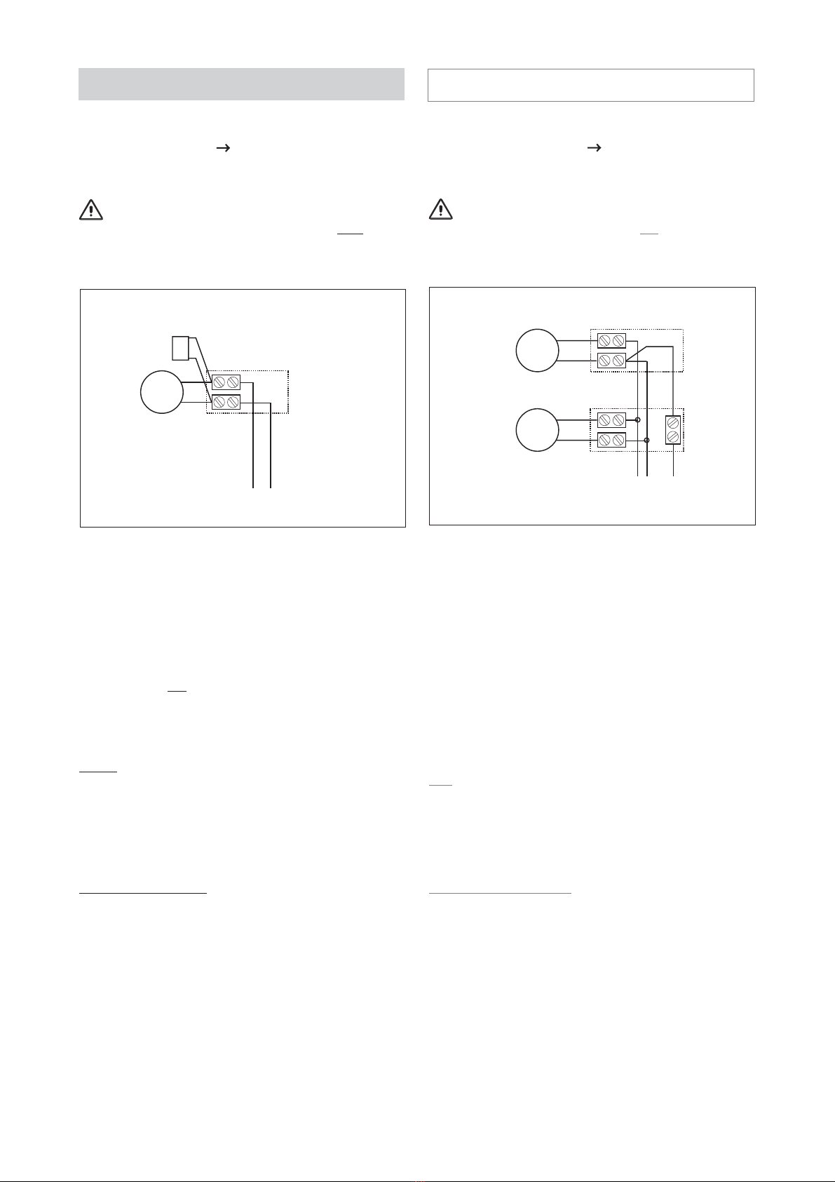
Warnung 230 V AC
Beachten Sie bei der Montage und Bedienung
Gefährliche Spannung. Kann Tod, schwere Körperverletzung oder
erheblichen Sachschaden verursachen. Trennen Sie das Gerät
allpolig von der Versorgungsspannung bevor Sie es öffnen,
montieren oder den Aufbau verändern. VDE 0100 für 230 V
Netzanschluss beachten.
Das Fenster schließt automatisch.
Beim Schließen und Öffnen stoppt der Antrieb über die
Lastabschaltung. Die entsprechende Druckkraft entnehmen Sie
bitte den technischen Daten. Die Druckkraft reicht aber auf jeden
Fall aus bei Unachtsamkeit Finger zu zerquetschen.
Bei der Montage und Bedienung nicht in den Fensterfalz und in
den laufenden Antrieb greifen!
Quetsch- und Klemmgefahr!
Sicherheitshinweise, die Sie beachten müssen,
werden
unbedingt
durch besondere Zeichen hervorgehoben
Caution / Attention / Warning
Caution / Attention / Warning
Caution / Attention / Warning
Danger to persons due to electricity
Non-observance leads to destruction
Danger to material due to incorrect handling
Danger to persons due to risks arising from the
operation of the equipment. Danger of crushing/trapping
INFO
Safety instructions
2
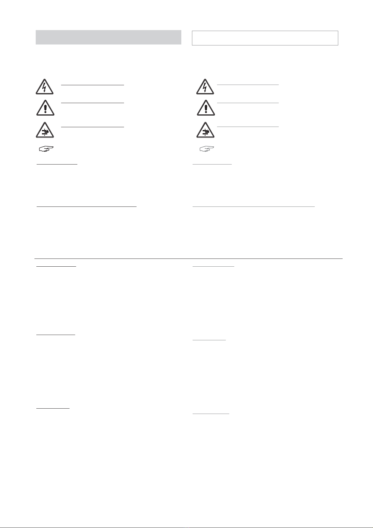
Warning 230 V AC
Dangerous voltage. Can cause death, serious injury or
considerable material damage. Disconnect the equipment from the
power supply at all poles before opening, assembling or carrying
out any structural alterations. Observe VDE 0100 for
230 V power connection.
Please observe the following for assembly and operation
The window closes automatically.
When opening and closing, the drive unit is stopped by the power
cut-off. The corresponding pressure force is listed in the technical
data. Take care - the pressure force is high enough to crush your
fingers.
During assembly and operation, do not interfere with the window
gap or the travelling drive
Danger of crushing/trapping!
Operating instructions
for professional assembly, installation and appropriate maintenance by
trained, qualified and safety-conscious electricians and/or skilled staff with
knowledge of electrical equipment installation.
Please observe the exact terminal assignment, the minimum and maximum
power ratings (see technical data) and the installation instructions.
It would be beyond the scope of these safety instructions to list all the valide
regulations and guidelines.
Always make sure that your system corresponds to the valid regulations. Pay
particular attention to: the aperture cross-section of the window, the opening
time and opening speed, the temperature resistance of the cables and
equipment, cross-sections of the cables in relation to the cable lengths and
power consumption.
Read and observe the information contained in these operating instructions
and respect the order of procedure stated therein.
Please keep these operating instructions for future reference and
maintenance. Reliable operation and the prevention of damage and risks are
only granted if the equipment is assembled carefully and the settings are
carried out according to these instructions and to the operating instructions
of the drives.
Exclusively for the automatic opening and closing of the stated types of
windows. For further application, please contact the manufacturer.
Required mounting material is to be adapted to the
frame and the corresponding load and is to be completed, if necessary. Any
supplied mounting material is only part of the required amount.
If the equipment is employed in smoke heat extraction systems (in short
SHE), they must be checked, serviced and, if required, repaired at least
once per year. This is also recommended for pure ventilation systems.
Free the equipment from any contamination. Check the tightness of fixing
and clamping screws. Test the equipment by trial run.
The gear system is maintenance free. Defective equipment must only be
repaired in our factory. Only original spare parts are to be used.
The readiness for operation has to be checked regularly. For this purpose a
service contract is recommended. All batteries provided with the SHE control
centre need to be regularly checked as part of the maintenance programme
and have to be replaced after their specified service life (approx. 4 years).
Please observe the legal requirements when disposing of hazardous
material - e.g. batteries.
Application range
Maintenance works
Bedienungsanleitung
Wartungsarbeiten
für die fachgerechte Montage, Installation und angemessene Wartung durch
den geschulten, sachkundigen und sicherheitsbewussten Elektro-Installateur
und / oder Fachpersonal mit Kenntnissen der elektrischen Geräteinstallation.
Lesen und Beachten Sie die Angaben in dieser Bedienungsanleitung und
halten Sie die vorgegebene Reihenfolge ein.
Diese Bedienungsanleitung für späteren Gebrauch / Wartung aufbewahren.
Ein zuverlässiger Betrieb und ein Vermeiden von Schäden und Gefahren ist
nur bei sorgfältiger Montage und Einstellung nach dieser Anleitung gegeben.
Bitte beachten Sie genau die Anschlussbelegung, die minimalen und
maximalen Leistungsdaten (siehe technischen Daten) und die
Installationshinweise.
Werden die Geräte in Rauch- und Wärmeabzugsanlagen (kurz RWA)
eingesetzt, müssen sie mindestens einmal jährlich geprüft, gewartet und ggf.
instand gesetzt werden. Bei reinen Lüftungsanlagen ist dies auch zu
empfehlen.
Die Geräte von Verunreinigungen befreien. Befestigungs- und Klemm-
schrauben auf festen Sitz prüfen. Die Geräte durch Probelauf testen. Das
Motorgetriebe ist wartungsfrei. Defekte Geräte dürfen nur in unserem Werk
instand gesetzt werden. Es sind nur Original-Ersatzteile einzusetzen. Die
Betriebsbereitschaft ist regelmäßig zu prüfen. Ein Wartungsvertrag ist
empfehlenswert. Alle serienmäßig mit der RWA-Steuerzentrale gelieferten
Akkus bedürfen einer regelmäßigen Kontrolle im Rahmen der Wartung und
sind nach der vorgeschriebenen Betriebszeit (ca. 4 Jahre) auszutauschen.
Bei der Entsorgung der verwendeten Gefahrstoffe - z.B. Akkus - Gesetze
beachten.
Anwendungsbereich
ausschließlich für automatisches Öffnen und Schließen der angegebenen
Fensterformen. Weitere Anwendungen im Werk erfragen.
Es würde den Rahmen dieser Bedienungsanleitung sprengen, alle gültigen
Bestimmungen und Richtlinien aufzulisten.
Prüfen Sie immer, ob Ihre Anlage den gültigen Bestimmungen entspricht.
Besondere Beachtung finden dabei: Öffnungsquerschnitt des Fensters,
Öffnungszeit und Öffnungsgeschwindigkeit, Temperaturbeständigkeit von
Kabel und Geräten. Benötigtes Befestigungsmaterial ist mit dem Baukörper
und der entsprechenden Belastung abzustimmen und, wenn nötig, zu
ergänzen. Ein eventuell mitgeliefertes Befestigungsmaterial entspricht nur
einem Teil der Erfordernisse.
Please observe the following safety which are emphasized
by special symbols