LisnaWaters LW-AU-S80-80x80-STEAM User manual

Installation and Operating Manual
INSTALLERS - PLEASE LEAVE THESE INSTRUCTIONS WITH
THE CUSTOMER
6 Years Part Warranty Upon Registeration within 120 days of Delivery:
Please visit to register your 6 years part warranty www.Lisnawaters.co.uk
LW-AU-S80-80x80-STEAM
LW-AU-S90-90x90-STEAM
LW-AU-S100-100x100-STEAM
LW-AU-S120-120x80 Le-STEAM
LW-AU-S120-120x80 Right-STEAM
Le-Hydro
Right-Hydro


C
B
B
A
EE
FJGJ
T
HL

x2
x2 x2
x4
x4 x4
x10
x4x4
x8
H1
H13
x2
x1
x2
x18
Ø5
x1
P
x1
K
x1
H7
x1
x2
H39 W
H2 H4
H5 H8
H10 H11 H12
H19 H20 H21 H22 H23
H35
x1
H6
x4
H3
x1
x1
3mm
5mm
Y
Y1
Y2 Y3 Y4
x2
H9
H14
St4x25 St4x16
St4x12
M5x16

1
x1
2
H35
C
H35
x1
C
x1
H22
x1
H23
2
1
3
3
H23
H22
H23
C
Step 1) Remove the transparent protection
film on shower tray.
Step 2) Refer to the steps to install drainer
onto shower tray. The drainer must
be fixed tight to shower tray to avoid
water leakage.
Step 3) Put the steamer drainer hose through
the corner hole on the tray, and connect it to the drainer.

2
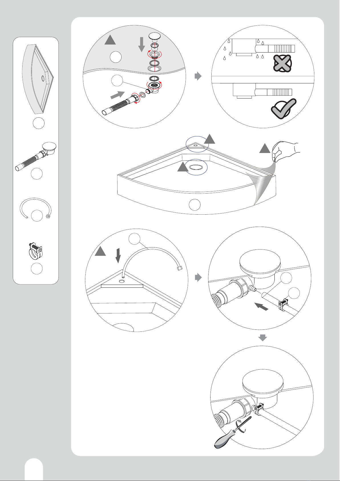
LEVELING AND FITTING THE TRAY
Step 1) Remove the protective film covering the base.
Step 2) Connect the soil pipe, trap and any couplings to the flexible waste under
the tub. You may choose to fit either a HEPV0 trap with the appropriate
couplings or choose to fit a McAlpine ST28M coupling to a McAlpine 28-NRV
trap.
Step 3) Position the tub base in what will be its final location and adjust the feet
until the base is level.
Step 4) You can raise/lower the feet under the tub and with a spirit level laid
across the tub, ensure the tub is level.
Step 5) Now fill the base with some water and check that the water flows
adequately to the plug and exits satisfactorily. If the water does not flow to the
plug fully, then you will need to increase the fall on the tray by adjusting the
legs. If the water does not exit the waste section fast enough, then ensure
there is suitable fall in the waste pipe and/or no blockage or kinks in the pipe
work.
Step 6) Check and attend to any leaks.
Step 7) Now slide the tub away from the wall to allow access all around the
shower as you assemble.
Step 8) This product is freestanding so you do not need to fix the feet to the
floor you will need to slide out for future maintenance.
Step 9) Take your time at this stage an ensure your levels are correct, this will
save a lot of time and effort throughout the build of your unit.

3
Step 1) Put the shower tray to corner of walls. Adjust legs of shower tray to
level the tray to complete horizontal.
Step 2) Pull out the tray to leave space for next steps installation.

4
T
H
T
HT
x1
HH
T
TG
TG
H
C
H
H
C
1
T
8
H
T
1
T
H
T
H
T
x1
Step 1) Put the middle column in position according to manual.
Step 2) One man holds the column steady, while 2nd person holds the side
panel ≥20mm higher than column. Follow the steps, to rotate the
profiles to correct position. Then put the side panel down to same
height like column.

5
8
1
TG
T
G
TG
TG
TG
G
T
G
T
TG
x1
G
G
H
C
1
T
Follow the same steps as in last page, to connect the other back panel glass.

6
12
20mm
40
20mm
4
0
1 2
x1
F
x1
L
FL
F L
GH
FL
GH
T
Step 1) Hold the aluminum wall profile≥20mm higher than back glass panel.
Follow the steps, to rotate the profile to correct position. Then put the
wall profile down to same height as back panel.
Step 2) Follow the Step 1) steps to install the other aluminum wall profile.
Mark: please note for cutting ends of wall profiles are direction to bottom.

x8
St4x25
B
B
H3
1
1
2
2
1
B
x2
x4
H3
H11
7
B
B
H11
H11
B2
H11
H11
B
5
3
F
F
B2
H11
H11
B
H11
H11
B
4
6
L
L
B
H3
2
34
B
56
B
L
F
Step 1) 2) Insert the PVC seals like in steps to both ends of aluminum profile
rails on top and bottom.
Step3) 4) 5) 6) Follow the manual steps to fix screws between profile rails and wall
profiles.
Mark: the wall profiles can be lifted≥20mm higher for easier fixing of the screws.

B2
B2
B2
B2
B
B
B
B
12
8
12
After up and bottom profiles rails are fixed. Lower down the front frame to the
same height as back panels.

9
x4
x4
x2
H8
H12
H12
H8
J
J
1
J
H8
H12
4
H8
H12
2
3
13
H12
H8 H8
H12
J
JJ
J
BS EN 12150
BS EN 12150
BS EN 12150
BS EN 12150
BS EN 12150
BS EN 12150
BS EN 12150
BS EN 12150
4
2
4
2J
J
J
J
BS EN 12150
Step 1)3) Hold the front small glass doors to correct direction with logo “BS EN 12150”.
Follow the steps to put small glass between up and bottom profiles. Then insert
the small glass to wall profiles.
Step 2)4) Install the plastic fixer where the holes are made on profiles.
St4x12

10
BS EN 121 50
BS EN 121 50
2
1
2
JJ
1
1
2
x2
H2
x2
H4
H2
H4
H4
H4
H2
H2
H2
Step 2) Install the water proof strips to small glass. Make
sure the waterproof strips in correct direction with
waterproof rim.
Step 1) Follow the steps to insert the seal strips into wall
profiles to fill the gap. This is to make the small glass
more steady not shaking. Then cut off the extra
length for seal strips.

11
K4 K1
K4
BS EN 121 50
BS EN 1215 0
1
3
1
2
T
3
P
M4x60
x1
Kx1
M4x20
M4x60
M4x60
x1
Y4
Y4
P
K
Step 1)2) Follow the steps to install glass shelf and sliding shower rail bar.
Step 3) Follow the steps to install the steam outlet.
ensure not to over tighten screws, as may cause glass to break

12
3
x2
E
H7
H7
1
H1
2
11
22
3
4
3
44
55
66
5
6
H7
x1
H1
x2
H5 x4
H6
H6
x4
H9
H9
H9
x1
E
EE
E
H5
Step 2) Fix waterproof seal strips H1 to sliding doors.
Step 1) Fix magnetic seal strips H7 to sliding doors.
Step 5)6) Please follow the steps to install the steam seal seals H9. Make sure to cut the
seals to length as in picture steps.
Step 3)4) Please follow the steps to install the up rollers and bottom rollers. 4 pieces of
rollers (2x up rollers, 2x bottom rollers) on each glass door.

2
H39
x2
13
33
14
BS EN 12150
BS EN 12150
3
3
11 1
2
44 44
2
Step 1) Hang the up rollers onto up profile rail. The bottom roller is different with
a button. Press the button to hook the bottom rollers onto down profile rail.
Step 3) Follow the steps to install door handles to glass doors.
Step 2) The up rollers are adjustable in height with a screwdriver, until the
magnetic seals are attached to each other without gap.
Mark:

13
14
II
H20
A
x1
x10
x10
Ø5
H13
H21
AA
A
x1
H
C
1
H20
H22
3mm
3mm
1
11
1
1
1
4
4
4
4
4
4
2
2
3
3
5
5
L
F
Y2
x1
H22
x1
H20
St4x16
Y2
Step 3) Fix top shower on acrylic roof. Then connect top shower hose to valve outlet.
Step 2) Follow the picture steps to install the ozone generator.
Step 1) Fix cabin body to shower tray at screw positions.
Step 4) Put acrylic roof on top and adjust roof to correct angle, fix the roof with
aluminum frame at screw holes.
This manual suits for next models
4
Popular Bathroom Fixture manuals by other brands

URIDAN
URIDAN ADMIRAL KH-10 installation instructions

noken
noken ACRO COMPACT 100080134 N380000003 manual

Canadian Timber Collection
Canadian Timber Collection CTC105 Parts Identification & Assembly Instructions

Signature Hardware
Signature Hardware BERWYN 953651 manual

T&S
T&S B-0133 Installation and maintenance instructions

Rohl
Rohl PERRIN & ROWE U.5886X/TO installation instructions