INSTALLATION INSTRUCTIONS
5461 W. Jefferson Blvd. Los Angeles, CA 90016 • P. 800-515-4880 • F. 800-972-4880 • www.liton.com Product specifications subject to change without notice. 08092021
CATALOG # : LCALD8 Adjustable Stem Assembly (STM6/12/24/36/48) Keep these instructions in a safe place for future use/reference.
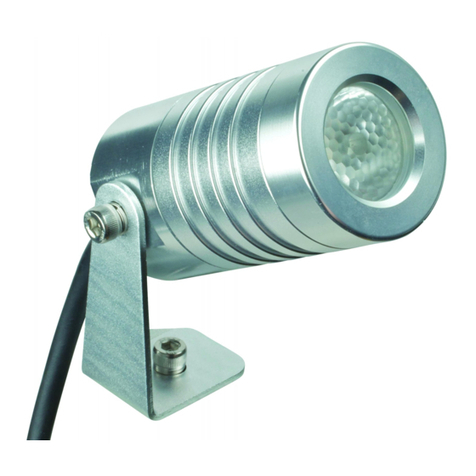
LCALD8 : 8" Lumen Cannon LED Pendant Architectural Downlight
For Damp and Dry Locations, alson for use with covered ceiling mount.
SAVE THESE INSTRUCTIONS
Page 3
• Warning Electrical Shock Hazard: All wiring should be done by a qualified electrical professional.
• Disconnect all power sources before attempting to install fixture.
• Adjustable Stem Assembly is rated for 50 lbs Maximum Static Loads Only (No dynamic or moving loads).
• Not for chemical or pool corrosive environments.
• To prevent the LCALD8 fixture with the Adjustable Stem Assembly from falling during installation secure the LCALD8 fixture with the Adjustable Stem Assembly
to the j-box with a cable (by others).
Warning: Make sure your junction box can support the combined weight of the LCALD8 (12lbs) and Adjustable Stem (-STM (FIG C).
Warning: Do not install the LCALD8 with the stem “-STM” (FIG C) on ceiling with a slope/slant of more than 40°. Check your
ceiling(s) slope./slant to make sure that that your ceiling is slanted less than 40° (FIG D). The LCALD8 with 8 Adjustable Stem
Assembly (-STM) can be on a ceiling with a maximum tilt of 40° (FIG D). Make sure to adjust/rotate the mounting bracket
(#2) on the junction box (by others) so the slot on the ball (#8) is facing the wall.
NOTE: The LCALD8 stem assembly “-STM” (FIG C) sits up in the 4” octagonal j-box (by others) 13/16” (FIG D). A deeper 4”
octagonal j-box (e.g.: by others) may be needed depending on your j-box wiring requirements.
Note: If shortening your supplied Stem (#14) to your desired length follow the instructions on page 4 before assembling and
installing the Adjustable Stem Assembly on the ceiling with the below instructions.
1) If not already installed then install the two (2) magnets (#6) with the two (2) 6-32 screws (#7) onto the Mounting Plate
(#2), (FIG A).
2) Mount the Mounting Plate (#2), using the four (4) slots (0.223“ wide x 0.890” long) to a 4” octagonal j-box (by others)
using j-box screws (by others). Tip: If you back off the j-box screws on the Mounting Plate (#2) then the Mounting Plate
(#2) will slide closer to j-box. Remember to tighten the j-box screws when the Half Ball Plate (#5), j–box and Mounting
Plate (#2) are in place.
3) Carefully pull wire conductors/cord (FIG C) through the fixtures Threaded fitting (FIG C), then through Adapter (#13, and
FIG C) and then out through the Adjustable Stem (#14). Make sure wire/cord is at least 6” longer out the Stem (#14 ) and
top of the canopy (FIG C) for easy installation.
4) Install the Adapter (#13) onto the Stem (#14) and tighten and then tighten the Adapter (#13) (on the Stem (#14))
onto the fixture's threaded fitting (FIG C).
5) Put the Canopy (#1) over the Stem (#14).
6) Place Half Ball Plate (#5) onto the Stem (#14).
7) Place Half Ball (#8) onto Stem (#14) and insert the Long 1/4”-20 Half Ball Socket Set Screw (#12), through the
tapped hole in the Half Ball (#8) & through the Stem's (#14) 1/8" hole. Then tighten the long 1/4”-20 Half Ball Socket
Set Screw (#12) using the supplied 1/8" allen wrench so the pin (on the end of the set screw (#12)) engages through
opposite 1/8” hole in the Stem (#14) and into the opposite Half Ball (#8) hole.
8) Insert the Bushing (4) into the U Retaining Bracket (#3) and slide onto the Half Ball Rectangular Plate (#5).
9) While securing fixture connect the power supply wiring (from j-box) to fixture wiring from the Stem #14). See "Wiring"
instructions below.
10) Hinge the Half Ball Rectangular Plate (#5), as shown, on the inside of the Mounting Plate (#2). Slide the Half Ball
Rectangular Plate (#5) in so that the tapped screw holes on the other side of the Half Ball Rectangular Plate (#5) align with
the Mounting Plate (#2). Secure in place with the 8-32 x 1/4” Long Screw (#9) (FIG A above).
11) Push the 5" Canopy (#1) up to Mounting Plate (#2) and onto the Magnets (#6) flush with the ceiling covering the
j-box.
Return fixture to Liton for servicing/replacing LED and LED drivers.
NOTE: Check fixture for input voltage before connecting power to fixture. Connect wiring in j-box. For dimming information
(wiring diagrams, chart, etc.) see LCALD8 web site page.
1. Connect ground wire (green or bare copper/aluminum) from the supply circuit to the ground wire (green or bare copper)
/screw/connector from the fixture.
2. Connect the neutral (common) wire from the power supply circuit to the neutral wire from the fixture.
3. Connect the main voltage supply wire (line/lead) from the power supply to the line (lead) wire from the fixture.
4. Secure connection using UL Listed wire nuts/connectors and then with UL Listed Electrical tape (by others), as required,
appropriate for the connection.
WIRING
RELAMPING
LCALD8 with STM installation
FIG D
LCALD8 (-STM) Maximum Fixture Tilt
The LCALD8 with stem (-STM) can mounting on a ceiling with a
40° Maximum slope/slant/tilt (see below).
FIG C
LCALD8 Wire/Cord
LCALD8 HOUSING
LCALD8 Wire/Cord
(6”+ out the top for
easy installation)
LCALD8
THREADED
FITTING
Adapter (#13)
Stem (#14)
40° MAX. TILT
(13/16”)
(4“ Oct. J-Box)
Ceiling
( 6”+)
2
6
7
3
5
10 9
FIG A FIG B
