Littelfuse Startco SE-330 Series User manual

Tel: +1-800-832-3873
E-mail: techline@littelfuse.com
www.littelfuse.com/SE-330
SE-330 SERIES (NEW REVISION) IEC 61850 INTERFACE
Revision 0-C-121117
Copyright 2018 Littelfuse Startco Ltd.
All rights reserved.
Document Number: PM-1206-EN

Page i
SE-330 Series (New Revision) IEC 61850 Interface Rev. 0-C-121117
This page intentionally left blank.

Page ii
SE-330 Series (New Revision) IEC 61850 Interface Rev. 0-C-121117
TABLE OFCONTENTS
SECTION PAGE
1 General ................................................................. 1
1.1 Configuration Software ......................................... 1
2 Network Configuration ....................................... 1
2.1 Ethernet Ports ........................................................ 1
2.2 IP Settings.............................................................. 1
2.3 SNTP Settings........................................................ 1
2.4 IEC 61850 Clients ................................................. 1
3 IEC 61850 Configuration.................................... 4
3.1 Server Configuration ............................................. 4
3.2 Report Control Blocks ........................................... 6
3.3 Data Sets ................................................................ 7
3.4 GOOSE Settings .................................................... 9
3.4.1 GOOSE Control Blocks ............................. 9
3.4.2 GOOSE Network Inputs............................. 9
4 MMS Data Model .............................................. 12
4.1 Device Information LLN0 ................................... 12
4.1.1 Report Control Blocks.............................. 12
4.1.2 Default Datasets ....................................... 13
4.1.3 GOOSE Control Blocks ........................... 13
4.2 Physical Device LPHD ........................................ 13
4.3 Metering UIRMMXU1........................................ 14
4.4 Ground Fault GFPTOC1 ..................................... 15
4.5 Resistor Fault RFPTOV1..................................... 16
4.6 Command CMDGGIO0 ...................................... 17
4.7 Event Record RECGGIO2................................... 18
5 Specifications...................................................... 19
Appendix A SE-330 Series (New Revision)
IEC 61850 Interface Revision History ........................ 20
LIST OFFIGURES
FIGURE PAGE
1 SE-MON330 Communications Settings................ 2
2 Top View of SE-330 (SE-330-X6-XX) with
Dual RJ-45 Ethernet Network Communications ... 2
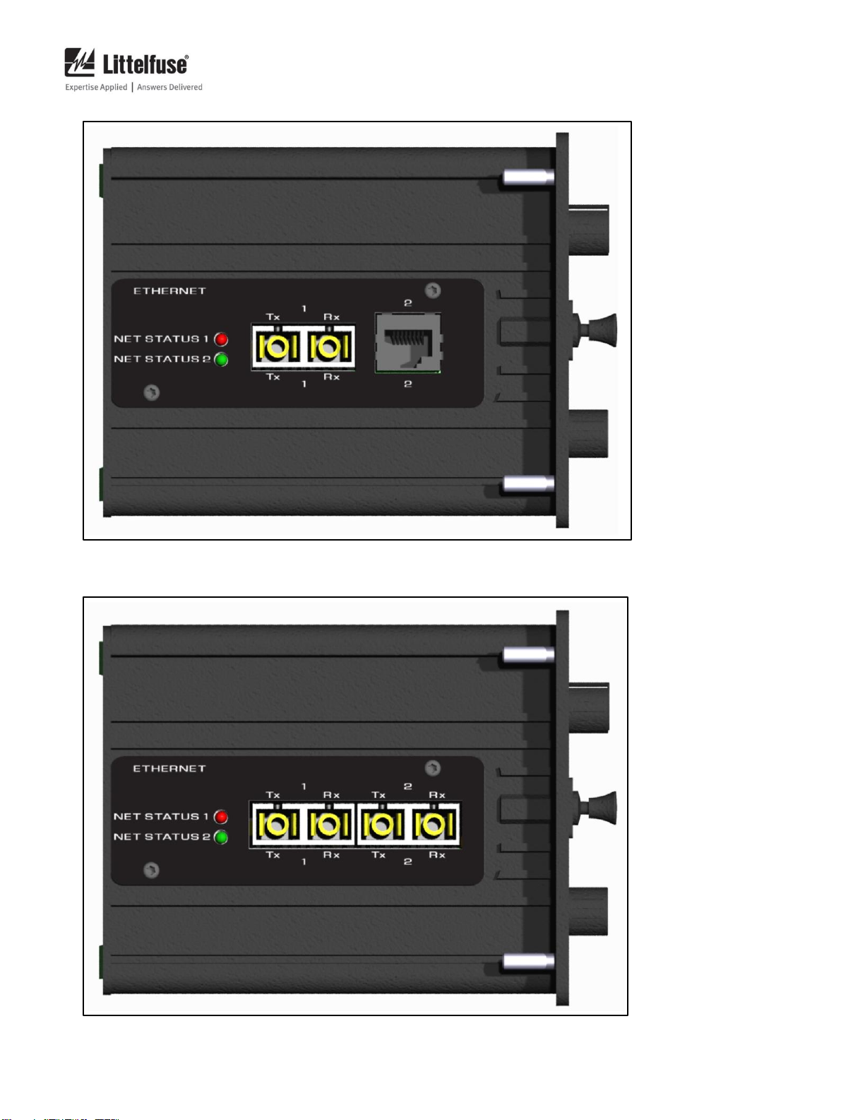
3 Top View of SE-330 (SE-330-X7-XX) with
Single Fiber SC and Single RJ-45
Ethernet Network Communications ...................... 3
4 Top View of SE-330 (SE-330-X8-XX)
with Dual Fiber SC Ethernet
Network Communications ..................................... 3
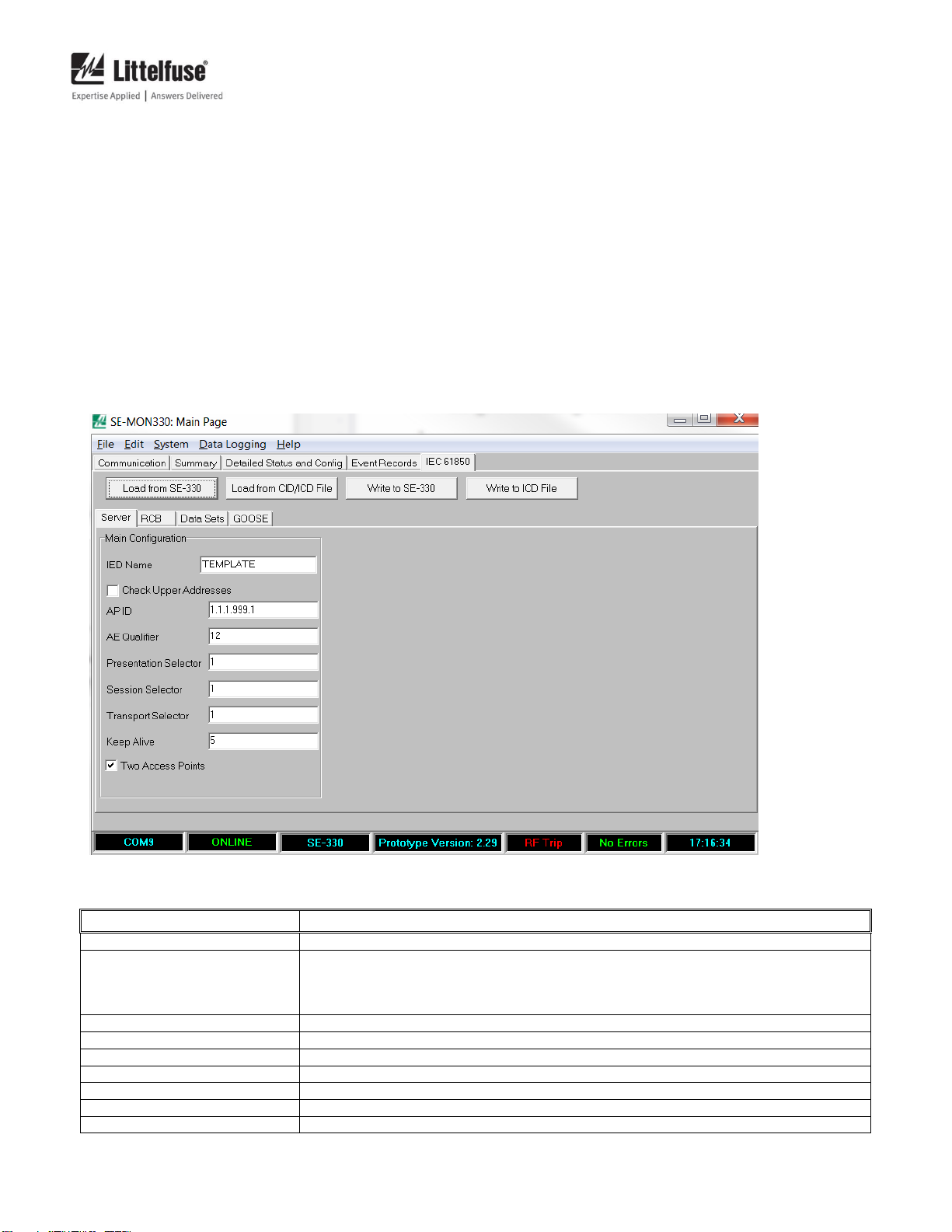
5 SE-MON330 IEC 61850 Server Configuration
Tab ......................................................................... 4
6 SE-MON330 IEC 61850 Report Control
Block (RCB) Configuration Tab ........................... 5
7 SE-MON330 IEC 61850 Data Sets Tab ................ 7
8 SE-MON330 IEC 61850 Data Set
Properties Window ................................................ 8
9 SE-MON330 IEC 61850 GOOSE Tab ................ 10
LIST OFTABLES
TABLE PAGE
1 Default IP Settings................................................. 1
2 Server Configuration Parameters .......................... 4
3 RCB Report Conditions......................................... 6
4 RCB Optional Fields ............................................. 6
5 GOOSE Network Input Status Values ................ 11
6 LLN0 –Logical Node Data................................. 12
7 LPHD –Logical Node Data ................................ 13
8 Metering UIRMMXU1........................................ 14
9 Ground Fault GFPTOC1 ..................................... 15
10 Resistor Fault RFPTOV1 .................................... 16
11 Command CMDGGIO0 ...................................... 17
12 Event Record RECGGIO2 .................................. 18
DISCLAIMER
Specifications are subject to change without notice.
Littelfuse Startco is not liable for contingent or consequential
damages, or for expenses sustained as a result of incorrect
application, incorrect adjustment, or a malfunction.

Page iii
SE-330 Series (New Revision) IEC 61850 Interface Rev. 0-C-121117
This page intentionally left blank.

Page 1
SE-330 Series (New Revision) IEC 61850 Interface Rev. 0-C-121117
1. GENERAL
This manual describes the features of the SE-330,
SE-330AU, and SE-330HV IEC 61850 interface. Unless
otherwise indicated, “SE-330”refers to all three monitor
series in general. The optional IEC 61850 interface
includes Manufacturing Message Specification (MMS)
and Generic Object Oriented Substation Events (GOOSE)
elements. MMS Buffered and Unbuffered Report Control
Blocks are supported with user-definable Data Sets. Two
GOOSE Control Blocks and 16 GOOSE Network Inputs
are available to provide high speed peer-to-peer signaling.
Three hardware configuration options are available to
provide redundant network connections: Dual RJ45, Dual
Fiber SC, and Single RJ45/Single Fiber SC.
The IEC 61850 interface is configured using the
SE-MON330 configuration software (version 3.2 or later).
Modbus/TCP is included to support configuration of the
SE-330 over the network. For more information on the
Modbus/TCP interface, refer to the SE-330 Series
Modbus/TCP manual.
1.1 CONFIGURATION SOFTWARE
The IP, SNTP and IEC 61850 settings are configured
using SE-MON330 through the front-panel USB interface.
To download SE-MON330, please visit
www.littelfuse.com/se-330. For information on how to
connect SE-MON330 to the SE-330, please refer tothe SE-
MON330 help file found in the Help –Contents menu.
2. NETWORK CONFIGURATION
IP and SNTP settings are configured on the
SE-MON330 Details Page tab as shown in Fig 1.
2.1 ETHERNET PORTS
Two Ethernet interface types are available for the
SE-330:
•10/100 BASE-Tx full/half duplex Auto-MDIX
RJ45
•100 Mbps fiber SC
Three combinations of these interface types are
available:
•Dual RJ45
•Dual Fiber SC
•Single RJ45 / Single Fiber SC
See Figs. 2, 3, and 4.
2.2 IP SETTINGS
When connected to the SE-330 with SE-MON330, the
IP settings can be found in the Details Page tab in the
Network Parameter section. The IP address, subnet mask
and gateway can be configured for each network interface.
Default values for these settings are listed in Table 1.
TABLE 1. DEFAULT IP SETTINGS
INTERFACE 1
IP Address
192.168.1.100
Subnet Mask
255.255.255.0
Gateway
0.0.0.0
INTERFACE 2
IP Address
192.168.2.100
Subnet Mask
255.255.255.0
Gateway
0.0.0.0
For troubleshooting network connections, the SE-330
supports ICMP ping requests.
Note: Ensure that each port is configured with a unique
IP address even if not used.
2.3 SNTP SETTINGS
When connected to the SE-330 with SE-MON330, the
SNTP Settings can be found in the Details Page tab in the
SNTP Parameter section. SNTP Enable, NTP Server IP
Address, Poll Period, and Timeout can be configured.
Enable the SNTP Client and set the NTP Server IP
Address to the address of the system NTP Server to
synchronize the SE-330 to the system time. For
troubleshooting connection problems with the NTP Server,
monitor the SNTP Client status. The status indicates
problems such as NTP Server not found, NTP Server not
running, and timeout.
The Poll Period is the time between queries to the NTP
server. The default value is 60 s, which is typically
sufficient to maintain time synchronization to 1 ms
accuracy, but it can be configured for periods as low as
1 s.
The Timeout is the maximum time that the SNTP Client
will wait for a response from the NTP Server. The default
value is 5 s, and the minimum time is 1 s. Ifa request fails,
no change is made to the SE-330 internal clock.
2.4IEC 61850 CLIENTS
The SE-330 IEC 61850 interface supports a total of four
simultaneous client connections. Client connection
requests are accepted in the order they are received and are
available on either network interface.

Page 2
SE-330 Series (New Revision) IEC 61850 Interface Rev. 0-C-121117
FIGURE 1. SE-MON330 Communications Settings.
FIGURE 2. Top View of SE-330 (SE-330-X6-XX) with Dual RJ-45 Ethernet Network Communications.

Page 3
SE-330 Series (New Revision) IEC 61850 Interface Rev. 0-C-121117
FIGURE 3. Top View of SE-330 (SE-330-X7-XX) with Single Fiber SC and Single RJ-45 Ethernet Network
Communications.
FIGURE 4. Top View of SE-330 (SE-330-X8-XX) with Dual Fiber SC Ethernet Network Communications.

Page 4
SE-330 Series (New Revision) IEC 61850 Interface Rev. 0-C-121117
3. IEC 61850 CONFIGURATION
The SE-330 IEC 61850 interface can be configured with
SE-MON330. The configuration can be loaded from an
SE-330 or from an ICD configuration file that has been
generated in an IEC 61850 system design tool. When the
IEC 61850 configuration is ready in SE-MON330, it can
be written to the SE-330 or to an ICD file.
IEC 61850 settings are visible in the IEC 61850 tab of
SE-MON330 when it is connected to an SE-330 with the
optional IEC 61850 interface. When SE-MON330 is first
connected, the IEC 61850 fields are empty. The
configuration can be loaded from the SE-330 by clicking
“Load From SE330” or from an ICD file by clicking “Load
From ICD File”. The configuration can then be
modified and written to the SE-330 by clicking “Write to
SE330”, or to an ICD file by clicking “Write to ICD File”.
After writing the configuration to the SE-330, cycle SE-
330 control power for the settings to take effect.
3.1 SERVER CONFIGURATION
The IEC 61850 server settings are configured through
the IEC 61850 Server tab in SE-MON330 as shown in Fig.
5.
The configuration includes the parameters listed in
Table 2.
FIGURE 5. SE-MON330 IEC 61850 Server Configuration Tab.
TABLE 2. SERVER CONFIGURATION PARAMETERS
PARAMETER
DESCRIPTION
IED Name
The user-definable name of the SE-330 on the IEC 61850 interface. Limited to 32 characters only.
Check Upper Addresses
Check this option to use the upper addresses including AE Qualifier, Application ID, Presentation
Selector, Session Selector and Transport Selector in addition to IP Address and TCP port for
connection validation. If unchecked, only the IP Address and TCP port will be used to validate the
connection.
AP ID
ACSE Application ID. Integer value between 0 and 65535.
AE Qualifier
OSI ACSE. AE Qualifier. Integer value between 0 and 65535.
Presentation Selector
OSI-PSEL. Presentation Selector. Integer value between 0 and 4294967295.
Session Selector
OSI-SSEL. Session Selector. Integer value between 0 and 65535.
Transport Selector
OSI-TSEL. Transport Selector. Integer value between 0 and 65535.
Keep Alive
The TCP Keep Alive period in seconds. The time it takes to detect a lost connection.
Two Access Points
Check this option to record both network interfaces to the ICD file.

Page 5
SE-330 Series (New Revision) IEC 61850 Interface Rev. 0-C-121117
FIGURE 6. SE-MON330 IEC 61850 Report Control Block (RCB) Configuration Tab.

Page 6
SE-330 Series (New Revision) IEC 61850 Interface Rev. 0-C-121117
3.2 REPORT CONTROL BLOCKS
The IEC 61850 interface includes four Buffered Report
Control Blocks (RCB) and four Unbuffered Report Control
Blocks. To configure the RCB’s, select the
IEC 61850 RCB tab in SE-MON330 as shown in Fig. 6.
RCB’s are used for data reporting to clients. Changes
made to the RCB configuration through SE-MON330
become the default settings. The RCB can be enabled or
disabled through the IEC 61850 interface.
The Data Set to be reported by the RCB is selected in the
Data Set field. Fixed or user-defined Data Sets can be
selected. See Section 3.3. The Report ID is a text
description of the RCB and has a maximum size of 64
characters.
The Config Revision allows the user to maintain control
of the configuration revision. In a commissioned system,
if the RCB configuration changes, the Config Revision
should be incremented.
For buffered RCB’s, the Buffering Time can be
configured. The default time is 1,000 ms. The minimum
time is 0 ms, and the maximum is limited only by the
64 kB buffer memory.
The RCB can be configured to generate a report at
specific intervals by setting the Integrity Period to a value
other than 0 ms and enabling the Integrity Triggering
Option.
RCB’s can be configured to generate data reports under
the conditions listed in Table 3.
Optional report contents can be configured in the
“Option fields”section. The optional fields are listed in
Table 4.
TABLE 3. RCB REPORT CONDITIONS
CONDITION
DESCRIPTION
Data Change
The report is sent when any of the Data Attributes of the Data Set associated with the
RCB have changed.
Quality Change
The report is sent when the Quality of any of the Data Attributes in the RCB’s Data
Set have changed.
Data Update
The report is sent when any of the Data Attributes are updated. Data may not change.
Timestamp will be updated.
Integrity
The report is sent at regular intervals.
General Interrogation
The client can request the present data values at any time.
TABLE 4. RCB OPTIONAL FIELDS
FIELD
DESCRIPTION
Sequence Number
The integer sequence number. Incremented after each transmission of the report
starting with 0 for the first report sent after the RCB is enabled.
Report Timestamp
Timestamp of the report at the time of transmission. Not necessarily the same as the
timestamp of the data within the report.
Reason for Inclusion
The trigger condition that caused the report to be sent.
Data Set Name
The name of the Data Set included in the report.
Data Reference
The data reference for the data included in the report.
Buffer Overflow
Indicates a buffer overflow occurred. Only available in Buffered RCB’s.
Entry ID
The ID of the report. Only available in Buffered RCB’s.
Configuration Revision
The revision of the RCB configuration.

Page 7
SE-330 Series (New Revision) IEC 61850 Interface Rev. 0-C-121117
3.3 DATA SETS
Data Sets are used to group elements of the MMS data
model for use in RCB’s and GOOSE Control Blocks
(GCB). Data Sets are viewed and edited using
SE-MON330 in the IEC 61850 Data Sets tab as shown in
Fig. 7.
The IEC 61850 interface includes three fixed Data Sets,
and 29 user-definable Data Sets. The three fixed Data Sets
are:
•LLN0$DS1_Measurement Data
•NGR Voltage
•NGR Impedance
•Ground-Fault Current Meter Values
•LLN0$DS2_Record Data
•Event Record Data for all events that are
recorded by the SE-330
•LLN0$DS3_GOOSE
•Ground-Fault Start
•Ground-Fault Operate
•Resistor-Fault Start
•Resistor-Fault Operate
•Remote Trip Status
The GCB’s are configured to use the LLNO$DS3
GOOSE Data Set. Refer to Section 3.4.1 for more
information on the GCB’s. For a detailed description of
the fixed Data Sets, refer to Section 4.1.2.
User-defined Data Sets can be added through SE-
MON330. To add a Data Set open the Data Sets tab and
click the “+” button. This will open the Data Set Properties
window as shown in Fig. 8. In the Data Set Properties
window, assign the Data Set to a Logical Node, give the
Data Set a unique name and choose data elements to
include in the Data Set. Data elements are chosen from the
data-model tree on the left, and can be added to the list on
the right by clicking the arrow buttons. Up to 30 data
elements can be added. Only data elements with a
functional constraint of ST orMX can be included in a Data
Set. When a data element has been added to the list on the
right, it can be moved up or down in the list with the up and
down arrow buttons, or removed from the list with the “X”
button.
FIGURE 7. SE-MON330 IEC 61850 Data Sets Tab.

Page 8
SE-330 Series (New Revision) IEC 61850 Interface Rev. 0-C-121117
FIGURE 8. SE-MON330 IEC 61850 Data Set Properties Window.

Page 9
SE-330 Series (New Revision) IEC 61850 Interface Rev. 0-C-121117
3.4 GOOSE SETTINGS
IEC 61850 GOOSE is used to provide network trip and
alarm signaling in place of or in addition to traditional relay
connections. The GOOSE configuration is viewed and
edited in the IEC 61850 GOOSE tab as shown in
Fig. 9.
GCB’s are configured to publish GOOSE data on the
system network. GOOSE Network Inputs are configured
to subscribe to GOOSE data that is available on the system
network.
3.4.1 GOOSE CONTROL BLOCKS
To support the redundant network interfaces on the
SE-330, two GCB’s are available. The GCB’s can be
independently enabled and can be configured to transmit
on one or both network interfaces.
Both GCB’s transmit the LLN0$DS3_GOOSE Data Set,
which includes the Ground-Fault Start, Ground-Fault
Operate, Resistor-Fault Start, Resistor-Fault Operate and
Remote Trip status. These data elements support network
signaling of all SE-330 trip conditions.
The GCB’s are configured independently with options
for the Destination MAC address, VLAN settings,
Application ID, GOOSE ID, Test flag, and Network
Interface. The Configuration Revision is not configurable
and is fixed at 1.
The Destination MAC address, Application ID and
GOOSE ID are used to uniquely identify the source of the
GOOSE data. Each of these values is assigned by the
system designer in consideration of all GOOSE publishers
and subscribers on the network.
The 48-bit MAC address is typically marked as a
multicast address by setting the least significant bit of the
most significant byte to 1.
The Application ID can be any integer value between 1
and 4095.
The GOOSE ID is a user-definable text identifier. It can
contain alpha-numeric characters and underscores and has
a maximum length of 64 characters.
VLAN ID and VLAN Priority configure Virtual LAN
routing of GOOSE messages through the network. VLAN
parameters are assigned by the system designer in
consideration of all other traffic on the system network. To
disable VLAN support, set the VLAN ID and VLAN
Priority to 0.
The GCB can be configured to assertthe Test flag which
informs subscribers totreat the GOOSE data as a test. How
test data is handled in the subscriber is dependent on the
specific device, but test data will typically not be used in a
trip decision.
The Network Interface can beset toInterface 1, Interface
2 or Interface 1 and 2. When set to Interface 1 and 2,
identical GOOSE messages are transmitted simultaneously
on both SE-330 network interfaces.
The reception of duplicate GOOSE messages by a
subscriber can cause undefined behavior, so the redundant
network topology must be considered when configuring
the GCB’s.
When connected to a subscriber with redundant network
interfaces through a fully redundant network, there is no
danger of duplicate GOOSE messages being received on
either of the subscriber’s network interfaces. In this case,
a single GCB can be configured to transmit messages on
Interface 1 and 2. This configuration can be supported in
the subscriber by configuring two Network Inputs, one for
each network interface.
When connected to a subscriber with redundant network
interfaces through a network on which the GOOSE
messages can cross to either side of the network and be
received on both network interfaces of the subscriber, the
GCB configuration depends on the behavior of the
subscriber. In this case, two GCB’s can be configured with
unique GOOSE configurations to be transmitted on
different network interfaces.
3.4.2 GOOSE NETWORK INPUTS
Up to 16 GOOSE Network Inputs are supported. The
Network Inputs drive the Remote Trip function within the
SE-330.
Network Input parameters must be configured to match
the desired GOOSE message. The Destination MAC
address, Application ID, Config Revision, and GOOSE ID
must all match the corresponding fields in the GOOSE
message.
The Network Inputs require a Boolean data attribute.
The Boolean data attribute can be received as a single
Boolean value, or as a member of a Boolean bit-string.
Configure the Data Index to the index of the desired
Boolean value in the GOOSE message. The first data
element is index 0. If the value is a Boolean bit-string,
configure the BitIndex tothe index ofthe desired bit within
the bit-string starting with index 0, otherwise set Bit Index
to 0.
The Boolean data can be inverted before it is used in the
trip decision by setting Inverted to Yes.
For troubleshooting Network Input configurations, the
status of each Network Input can be viewed in the
IEC 61850 GOOSE tab under NI Status. The Network
Input status values are listed in Table 5. The Network Input
is colored green when the received value will not cause a
Remote Trip, red when the received value will cause a
Remote Trip, and yellow when the received value will be
ignored due to the Network Input configuration.

Page 10
SE-330 Series (New Revision) IEC 61850 Interface Rev. 0-C-121117
FIGURE 9. SE-MON330 IEC 61850 GOOSE Tab.
The Network Inputs are combined in a logical OR
operation to drive the Remote Trip function within the SE-
330. Disabled Network Inputs and Network Inputs with a
status other than OK are not included in the trip decision.
The Boolean equation for the trip status of each Network
Input is shown in Equation 3.1:
Equation 3.2 is the Boolean equation for the
combination of the Network Inputs in the Remote Trip
decision:

Page 11
SE-330 Series (New Revision) IEC 61850 Interface Rev. 0-C-121117
TABLE 5. GOOSE NETWORK INPUT STATUS VALUES
STATUS
DESCRIPTION
OK
The GOOSE messages are being received within the Time To Live period or the
Network Input is disabled.
No Data
No GOOSE messages matching the Network Input configuration are being received.
Old
GOOSE messages have been received in the past, but they are no longer being
received.
Bad Type
The Data Attribute specified in the Data Index field is not a Boolean bit-string value.
Test
The Test flag is set on the GOOSE messages.
Needs Commissioning
The Needs Commissioning flag is set on the GOOSE messages.

Page 12
SE-330 Series (New Revision) IEC 61850 Interface Rev. 0-C-121117
4. MMS DATA MODEL
The SE-330 IEC 61850 interface includes a single
logical device that contains multiple logical nodes. The
logical nodes are described in this section.
4.1 DEVICE INFORMATION LLN0
The LLN0 Logical Node contains device information as
listed in Table 6.
4.1.1 REPORT CONTROL BLOCKS
The LLN0 Logical Node contains four bufferedand four
unbuffered RCB’s.
RCB’s can be configured with SE-MON330 or through
the IEC 61850 interface.
Buffered RCB’s are named brcb01, brcb02, brcb03, and
brcb04, and unbuffered RCB’s are named urcb01, urcb02,
urcb03, and urcb04.
TABLE 6. LLN0 –LOGICAL NODE DATA
DATA
OBJECT
NAME
DATA
OBJECT
TYPE
DATA
ATTRIBUTE
NAME
DATA
ATTRIBUTE
TYPE
DESCRIPTION
Mod
INC
stVal
INT8
Mode for whole logical device (status only):
1 ON
2 Blocked
3 Test
4 Test-blocked
5 OFF
Beh
INS
stVal
INT8
Behaviour reflecting mode for whole logical device:
1 ON
2 Blocked
3 Test
4 Test-blocked
5 OFF
Health
INS
stVal
INT8
The Health value reports the most severe error condition for all Logical
Nodes in the Logical Device:
1 OK –No Problems, Normal Operation
2 Warning –Minor Problems, but in Safe Operation Mode
-SD Card Full
3 Alarm –Severe Problem, No Operation Possible
-ADC Error
-NVRAM Error
-FLASH Error
-Hardware Fault
-CT Error
-Calibration Error
-Firmware Fault
NamPlt
LPL
vendor
swRev
d
configRev
ldNS
VS255
VS255
VS255
VS255
VS255
Vendor name: “Littelfuse Inc.”
Firmware Version
Description: “SE-330 Neutral Grounding Resistor Monitor”
Configuration Revision
Logical Device Name Space “IEC61850-7-4: 2003”

Page 13
SE-330 Series (New Revision) IEC 61850 Interface Rev. 0-C-121117
4.1.2 FIXED DATASETS
The LLN0 Logical Node contains two predefined Data
Sets with following contents:
Data Set DS1_Measurement
•UIRMMXU1.A (MX)
•UIRMMXU1.PhV (MX)
•UIRMMXU1.Z (MX)
Data Set DS2_Record
•GFPTOC1.Str (ST)
•GFPTOC1.Op (ST)
•RFPTOV1.Str (ST)
•RFPTOV1.Op (ST)
•RecGGIO2.AnIn1 (MX)
•RecGGIO2.AnIn2 (MX)
•RecGGIO2.AnIn3 (MX)
•RecGGIO2.Ind1 (ST)
•RecGGIO2.Ind2 (ST)
•RecGGIO2.Ind3 (ST)
•RecGGIO2.Ind4 (ST)
•RecGGIO2.Ind5 (ST)
•RecGGIO2.Ind6 (ST)
•RecGGIO2.Ind7 (ST)
•RecGGIO2.Ind8 (ST)
•RecGGIO2.Ind9 (ST)
•RecGGIO2.Ind10 (ST)
•RecGGIO2.Ind11 (ST)
•RecGGIO2.Ind12 (ST)
•RecGGIO2.Ind13 (ST)
•RecGGIO2.Ind14 (ST)
•RecGGIO2.Ind15 (ST)
•RecGGIO2.Ind16 (ST)
•RecGGIO2.Ind17 (ST)
•RecGGIO2.Ind18 (ST)
•RecGGIO2.Ind19 (ST)
•RecGGIO2.Ind18 (ST)
•RecGGIO2.Ind19 (ST)
•LLN0.Health (ST)
•LPHD1.PhyHealth (ST)
Data Set DS3_GOOSE
•RFTPOV1.StrVal.general (ST)
•RFTPOV1.Op.general (ST)
•GFTPOC1.StrVal.general (ST)
•GFTPOC1.Op.general (ST)
•CMDGGIO1.SPCSO.stVal (ST)
4.1.3 GOOSE CONTROL BLOCKS
The LLN0 Logical Node contains two GCB’s: gcb1 and
gcb2. The configuration for gcb1 and gcb2 includes the
DS3_GOOSE Data Set which cannot be changed.
4.2 PHYSICAL DEVICE LPHD
The LPHD Logical Node contains the physical device
information as listed in Table 7.
TABLE 7. LPHD –LOGICAL NODE DATA
DATA
OBJECT
NAME
DATA
OBJECT
TYPE
DATA
ATTRIBUTE
NAME
DATA
ATTRIBUTE
TYPE
DESCRIPTION
PhyNam
DPL
vendor
hwRev
swRev
serNum
model
VS255
VS255
VS255
VS255
VS255
Vendor Name: “Littelfuse Inc.”
The Hardware Revision
The Firmware Revision
The Unit Serial Number
“SE-330”or ”SE-330AU”or “SE-330HV”
PhyHealth
INS
stVal
INT8
Physical Device Health:
1 OK –No Problems, Normal Operation
2 Warning –Minor Problems, but in Safe Operation Mode
3 Alarm –Severe Problem, No Operation Possible
Proxy
SPS
stVal
BOOL
TRUE = indicates that the LN is a proxy.

Page 14
SE-330 Series (New Revision) IEC 61850 Interface Rev. 0-C-121117
4.3 METERING UIRMMXU1
The Metering Logical Node contains data objects for the
three metered values as listed in Table 8.
TABLE 8. METERING UIRMMXU1
DATA
OBJECT
NAME
DATA
OBJECT
TYPE
DATA
ATTRIBUTE
NAME
DATA
ATTRIBUTE
TYPE
DESCRIPTION
Mod
INC
stVal
ctlModel
INT8
Mode for whole logical node (status only):
1 ON
2 Blocked
3 Test
4 Test-blocked
5 OFF
Status-Only
Beh
INS
stVal
INT8
Behaviour reflecting mode for whole logical node:
1 ON
2 Blocked
3 Test
4 Test-blocked
5 OFF
Health
INS
stVal
INT8
Logical Node Health:
1 OK –No Problems, Normal Operation
2 Warning –Minor Problems, but in
Safe Operation Mode
3 Alarm –Severe Problem, No Operation Possible
NamPlt
LPL
vendor
swRev
d
VS255
VS255
VS255
Vendor Name: “Littelfuse Inc.”
Firmware Version
Description: “Neutral line measurements”
PhV
WYE
neut.cVal.ma
g.f
FLOAT
Neutral grounding resistor voltage in volts.
A
WYE
neut.cVal.ma
g.f
FLOAT
Neutral grounding resistor current in amps.
Z
WYE
neut.cVal.ma
g.f
FLOAT
Neutral grounding resistor resistance in ohms.

Page 15
SE-330 Series (New Revision) IEC 61850 Interface Rev. 0-C-121117
4.4 GROUND FAULT GFPTOC1
The Ground-Fault Logical Node contains data elements
that are associated with the ground-fault function of the
SE-330 as listed in Table 9.
TABLE 9. GROUND FAULT GFPTOC1
DATA
OBJECT
NAME
DATA
OBJECT
TYPE
DATA
ATTRIBUTE
NAME
DATA
ATTRIBUTE
TYPE
DESCRIPTION
Mod
INC
stVal
ctlModel
INT8
Mode for whole logical node (status only):
1 ON
2 Blocked
3 Test
4 Test-blocked
5 OFF
Status-Only
Beh
INS
stVal
INT8
Behavior reflecting mode for whole logical node:
1 ON
2 Blocked
3 Test
4 Test-blocked
5 OFF
Health
INS
stVal
INT8
Logical Node Health:
1 OK –No Problems, Normal Operation
2 Warning –Minor Problems, but in
Safe Operation Mode
3 Alarm –Severe Problem, No Operation Possible
NamPlt
LPL
vendor
swRev
d
VS255
VS255
VS255
Vendor Name: “Littelfuse Inc.”
Firmware Version
Description: “Io>”
Str
ACD
general
dirGeneral
BOOL
INT8
Start. Ground Fault Condition Detected.
Unknown
Op
ACT
general
BOOL
Operate. Ground Fault tripped.
StrVal
ASG
setMag.f
FLOAT
GF Trip Level [A] as configured through the front-panel GF Trip Level
dial.
OpDlTmms
ING
setVal
INT32
Operate Delay Time [ms] as configured through the front-panel GF Trip
Time dial.

Page 16
SE-330 Series (New Revision) IEC 61850 Interface Rev. 0-C-121117
4.5RESISTOR FAULT RFPTOV1
The Resistor Fault Logical Node contains data elements
associated with the Neutral Grounding Resistor (NGR)
monitoring function of the SE-330. The data elements are
listed in Table 10.
TABLE 10. RESISTOR FAULT RFPTOV1
DATA
OBJECT
NAME
DATA
OBJECT
TYPE
DATA
ATTRIBUTE
NAME
DATA
ATTRIBUTE
TYPE
DESCRIPTION
Mod
INC
stVal
ctlModel
INT8
Mode for whole logical node (status only):
1 ON
2 Blocked
3 Test
4 Test-blocked
5 OFF
Status Only
Beh
INS
stVal
INT8
Behavior reflecting mode for whole logical node:
1 ON
2 Blocked
3 Test
4 Test-blocked
5 OFF
Health
INS
stVal
INT8
Logical Node Health:
1 OK –No Problems, Normal Operation
2 Warning –Minor Problems, but in
Safe Operation Mode
3 Alarm –Severe Problem, No Operation Possible
NamPlt
LPL
vendor
swRev
d
VS255
VS255
VS255
Vendor Name: “Littelfuse Inc.”
Firmware Version
Description: “Uo>”
Str
ACD
general
dirGeneral
BOOL
UINT8
Start. Resistor Fault condition detected.
Unknown
Op
ACT
general
BOOL
Operate. Resistor Fault tripped.
StrVal
ASG
setMag.f
FLOAT
Resistor Fault trip voltage [V] as configured through the front panel VN
Trip Level dial.
OpDlTmms
ING
setVal
INT32
Operate Delay Time [ms]. Fixed at 12,000 ms.
Other manuals for SE-330 Series
1
This manual suits for next models
3
Table of contents