ENGLISH
2P/N 192061515 Rev AA April 2019
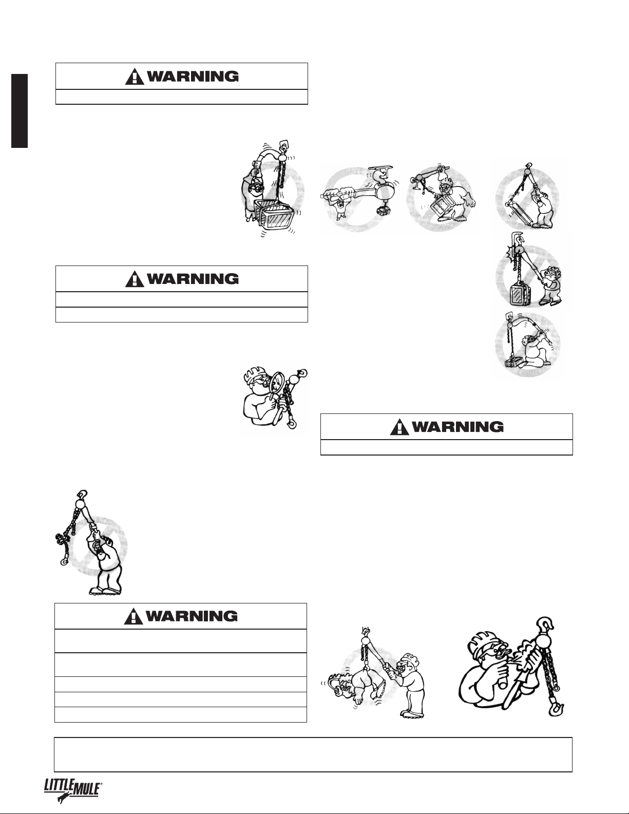
Improper operation of a hoist can create a potentially hazardous
situation which, if not avoided, could result in death, or serious
injury. To avoid such a potentially hazardous situation, the
operator shall:
1. NOT operate a malfunctioning or unusually performing hoist.
2. NOT operate the hoist until you have thoroughly read and
understood this manual.
3. NOT operate a hoist which has been modied without the
manufacturer’s approval or certication to be in conformity
with applicable OSHA regulations.
4. NOT lift or pull more than rated load for the hoist.
5. NOT use damaged hoist or hoist that is not working properly.
6. NOT use hoist with twisted, kinked, damaged,
or worn strap.
7. NOT operate with any lever extension (cheater bar).
8. NOT attempt to "free wheel" the hoist while a load is applied.
9. NOT use the hoist to lift, support, or transport people.
10. NOT lift loads over people and make sure all personnel
remain clear of supported load.
11. NOT attempt to lengthen the hoist strap or repair damaged
hoist strap.
12. Protect the hoists strap from weld splatter or other damaging
contaminants.
13. NOT operate a hoist when it is restricted from forming a
straight line from hook to hook in the direction of loading.
14. NOT use hoist strap as a sling or wrap hoist strap around load.
15. NOT apply the load to the tip of the hook or to the hook latch.
16. NOT apply load unless hoist strap is properly seated in the
drum.
17. NOT apply load if bearing prevents equal loading on all load
supporting chains.
18. NOT operate beyond the limits of the load chain travel.
19. NOT leave load supported by the hoist unattended unless
specic precautions have been taken.
20. NOT allow the strap hoist or hook to be used as an electrical
or welding ground.
21. NOT allow the strap hoist or hook to be touched by a live
welding electrode.
22. NOT remove or obscure the warnings on the hoist.
23. NOT operate a hoist which has Not been securely attached
to a suitable support.
24. NOT operate a hoist unless load slings or other approved
single attachments are properly sized and seated in the
hook saddle.
25. NOT lift loads that are Not balanced and the holding action
is Not secure, taking up slack carefully.
26. NOT operate a hoist unless all persons are and remain clear
of the supported load.
27. Report malfunctions or unusual performances of a hoist,
after it has been shut down until repaired.
28. NOT operate a hoist on which the safety placards or decals
are missing or illegible.
29. Be familiar with operating controls, procedures and warnings.
Improper operation of a hoist can create a potentially hazardous
situation which, if not avoided, could result in minor or moderate
injury. To avoid such a potentially hazardous situation, the
operator shall:
1. Maintain a rm footing or be otherwise secured when
operating the hoist.
2. Check ratchet and pawl function by tensioning the hoist prior
to each lift or pulling operation.
3. Use hook latches. Latches are to retain slings, chains, etc.
under slack conditions only.
4. Make sure the hook latches are closed and not supporting
any parts of the load.
5. Make sure the load is free to move and will clear all
obstructions.
6. Avoid swinging the load or hook.
7. Avoid lever “y-back” by keeping a rm grip on the lever until
operating stroke is completed and lever is at rest.
8. Inspect the hoist regularly, replace damaged or worn parts,
and keep appropriate records of maintenance.
9. Use Columbus McKinnon parts when repairing the unit.
10. NOT use the hoist load limiting or warning device to measure
load.
11. NOT operate except with manual power.
12. NOT permit more than one operator to pull on lever at the same
time. More than one operator is likely to cause hoist overload.
13. NOT allow your attention to be diverted from operating
the hoist.
14. NOT allow the hoist to be subjected to sharp contact with
other hoists, structures, or objects through misuse.
15. NOT adjust or repair the hoist unless qualied to perform
such adjustments or repairs.
The hoists are intended for general industrial use for
moving loads within their load ratings. Prior to installation
and operation, the user should review the application for
abnormal environmental or handling conditions.
GENERAL SAFETY INFORMATION
Each LITTLE MULE Lineman's Hoist is built in accordance with
the specications contained herein and at the time of manufacture
complied with our interpretation of applicable sections of the
*American Society of Mechanical Engineers Code B30.21. Columbus
McKinnon Corporation cannot be responsible for applications other
than those for which Little Mule equipment is intended. *Copies of
this standard can be obtained from ASME Order Department, 22
Law Drive, Box 2300, Faireld, NJ 07007-2300, U.S.A.
WARNING
This symbol points out important safety instructions which
if not followed could endanger the personal safety and/
or property of yourself and others. Read and follow all
instructions in this manual and any provided with the
equipment before attempting to operate your lodestar hoist.
MOVING HAZARDOUS LOADS
The hoists are not recommended for lifting materials that could
cause widespread damage if dropped. The lifting or moving of
materials that could explode or cause chemical or radioactive
contamination requires fail-safe, redundant supporting devices that
are not incorporated into these hoists.