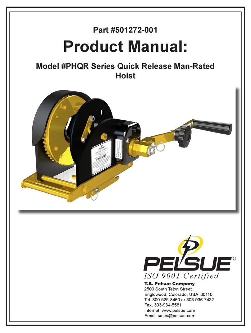
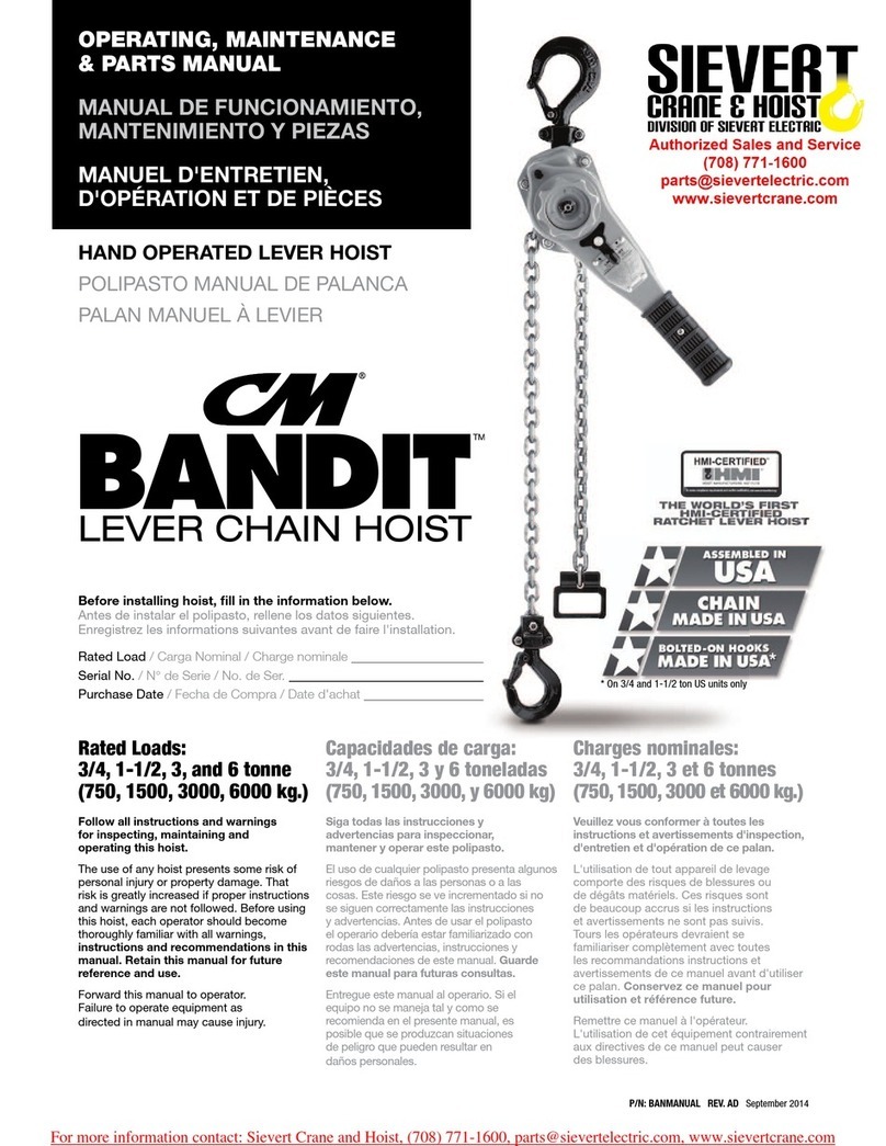
little mule 2000A Manual

Li
®
an'
oists
Model
2000A
2000DA
perating and
aintenance
Instructions
PUBLICATION PART NO. RLB-680
IMPORTANT
-IACAUTION
I
This manual contains
important
information
for
the
correct
installation,
operation
and
maintenance
of
the equipment described herein. All
persons
involved
in
such
installation, operation, and maintenance
should
be
thoroughly
familiar with the contents.
To
safeguard againstthe
possibility
of
personal
injury
or
property
damage,
follow
the
recommendations
and
instructions
of
this
manual and keep
it
for
further reference.
IAWARNING!
The equipment shown
in
this
manual
is
intended
for
industrial
use
only
and
should
not
be
used
to
lift,
support,
or
otherwise
transport
people,
or
to
suspend
unattended loads
over
people.

lA-WARNING
\-
To
Avoid Injury
Do
not
operate
damaged
or
malfunctioning hoist.
Do
not
lift more
than
rated
load.
Do
not
lift people
or
loads over people.
Do
not
operate
with twisted, fouled
or
damaged
web
strap.
Do
not
use a
handle
extension.
Do
not
operate
hoist unless hoist body, web
strap
and
load
block
or
hook
are
in a
straight
line.
Do
not
operate
hoist until load is properly seated
in
hook.
Do
not
attempt
to free wheel web
strap
with
a
load
on
hoist.
Do not use hoist web
strap
for
a sling
or
drag
strap
under
load.
Do
not
operate
except
with
hand
power.
Do
not
remove
or
obscure
the
warning
decal.
Do
not
allow web
strap
and
hoist to
be
dirty
-clean
and
dry
thoroughly.
Relubricate
hoist.
IA-
DANGER
1-
To
Avoid Electrical Shock
The
web
strap
on
this hoist is NOT
an
insulating
member.
When
clean
and
dry, the
strap
may
have
dielectric properties typical
of
nylon
or
polyester
fibers.
Use
an
appropriate
insulating
member
in series
with hoist
and
web
strap
to achieve
proper
working
distances
per
OSHA Regulation
Subpart
V,
1926.950
or
your
company
work
practices.
When
handle
swings closer to energized
conductors
than
permis-
sible OSHA safe
working
distances
or
company
practices, use
appropriate
clothing
and
rubber
gloves
for
rated
voltages.
OSHA REGULATION SUBPART
V,
1926.950 TABLE V-I
Alternating Current -Minimum Distances
Voltage Range Minimum VoltageRange
Minimum
(Phase
to
Phase) Working Distance (Phase
to
Phase)
Working
Distance
Kilovolt Kilovolt
2.1
to 15 2 ft. 0 in.
161
to 169 3 ft. 8 in.
15.1 to 35 2 ft. 4 in. 230 to 242 5 ft. 0 in.
35.1 to 46 2 ft. 6 in. 345 to 362 7 ft. 0 in.
46.1 to 72.5 3 ft. 0 in. 500 to 552
11
ft. 0 in.
72.6 to
121
3 ft. 4 in.
700
to 765 15 ft. 0 in.
138 to 145 3 ft. 6 in.
3

INTRODUCTION
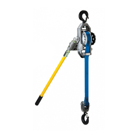
This Lineman's web strap hoist utilizes a friction type
holding brake to provide more precise positioning than is
available with ratchet-and-pawl design hoists. The
nonmetallic webbing and handle provide an extra
measure
of
safety for use around energized power lines.
The hoist should not be used as a substitute for approved
insulators when tensioning energized lines. The model
2000A has pawls that are operable with hot sticks. In
addition, the model 2000DA has hot stick rings on all
hooks and the operating handle.
2000A Specifications
Single Line Double Line
Capacity 10001bs. 2000 Ibs.
Min. Distance Between Hooks ,
17
1h in. 22 in.
Maximum Lift Distance
11
ft. ! 5 ft.
Rated Web Strength 4000 Ibs. 80001bs.
Weight 121/41bs. 121/41bs.
Holdfng Pawl:
Lif! to Freewheel
Figure
1
Handle
Pawl
OPERATION
Safety Notes:
1.
Be sure hoist is clean and dry before using. This is
important to assure proper brake action in addition to
maintaining the hoist's dielectric qualities.
2.
Be sure webbing is wound smoothly on the drum and
is not twisted at any point.
3.
Do not side pull; make sure hoist can align itself with
the direction
of
loading.
4. Do not wrap the webbing around the
load-use
a
proper sling.
5.
Raise the load only enough to make the webbing
tight
then double check the rigging to see that hooks are
securely seated before continuing the lift.
6.
Do not lift people or loads over people.
7. Do not use a damaged or malfunctioning hoist.
8.
Do not overload. Any crack in the handle is evidence
of
serious overloading.
4
lifting
or
Pulling
Place handle pawl in the "raise" position by pulling
straight out on the handle pawl ring and rotating it until
the word "UP" faces the operator (see Fig. 1). Wind the
handwheel until the web is tight. The handle may be
stroked through any convenient angle to lift the load.
Lowering
Place handle pawl in the "lower" position by pulling out
and rotating the handle pawl ring until the letters
"DN"
show (see Fig.
1).
Again, the handle may be moved
through any desired angle to lower the load.
Free Wheeling (No
load
on
hoist)
Place handle pawl in the middle position between
"UP"
and "DN." Lift and hold the holding pawl clear
of
the
ratchet teeth (see Fig. 1). The strap may now be pulled
freely from the drum. Excess slack can be quickly
rewound on the drum by turning the handwheel, with
or without the holding pawl raised.

MAINTENANCE
General
Maintenance
of
the hoist is normally limited to cleaning
and lubrication. Care should be taken
in
either
of
these
procedures to avoid wetting
of
the brake with water or
solvents.
Cleaning
Unless the hoist has been disassembled, cleaning
of
its
mechanism should be limited to wiping with a damp
cloth or a dry, stiff brush,
in
order to avoid brake disc
contamination.
If
the webbing requires a thorough
cleaning, it should be removed (see below), washed in a
mild detergent and water and thoroughly dried before
using hoist.
lubrication
Relubrication should not be required unless
the
hoist has
had original lubrication removed during cleaning
of
parts. Lubricate the following points with a very light
coat
of
a good multi-purpose grease: (a) square thread on
end
of
drum shaft, (b) inside
of
handle where it turns on
hub, (c) holding pawl pivot bushing, (d)
bottom
idler pin.
Relubricate the porous bronze main frame bushings by
applying one or two drops
of
clean motor oil, allowing
to
soak in, and wiping away any excess.
REPAIR
General
Instructions given here are limited to replacing parts that
are most likely to wear during normal use. Replacement
of
any other parts are straight forward removal and
replacement.
Strap Replacement
Unwind strap from drum. Remove bottom yoke by
removing yoke pin and remove idler block. Use a lis"
drive punch to remove pin from the handwheel and
remove handwheel. Withdraw the drum shaft, handle,
and ratchet as a complete unit. Remove old strap from
slot in drum. Insert one end
of
the new strap assembly in
the drum slot so that the cut end
of
the webbing will
wind
up
against the drum. Use the drive punch to open
5
the eye in the strap and reinstall the drum shaft,
handwheel, and pin. Slip idler block over end
of
strap
and replace bottom block, being sure retaining rings are
secure.
Brake Disc Replacement
Holding handwheel, remove screw from otherend
of
drum
shaft. Remove handle cap, thread stop, and handle. Turn
handle hub clockwise to remove.
Replace brake discs andlor ratchet being careful to keep
parts clean and free
of
grease
or
oil. Replace hub and
handle, regreasing
if
needed. Replace thread stop so that
hub can back off only enough to release brake. With hub
screwed down tight, the clearance between the thread stop
ear and the hub shoulder should be l/S" to
5/]6".
Replace
handle cap and screw.

2000A
2000DA
12
14~
15 ,
27
13
26
__
'[\
\'
41
30
43
_~'"
\
43
6
4,
6
28
29
32
37
~.

PARTS LIST
Item
Description
Part
No. Item i Description
Part
No.
1 Hook with Latch 24 25 Pawl Trigger RLB-25
2 Slotted
Nut
16
3 Pin H-5250
4 I Pin 73-1
26 Fiberglass Handle I 350
27 Fiberglass Handle with Ring 350SPL
28 Drum RLB-16
I
5 Pin H-5273 29 Strap 3471112
6 Handwheel 32R 30 Retaining Ring 322RR
7 Frame RLB-18
31
Shaft
396R
8
Bearing
RLB-530 32 Swivel Shackle 3433
9 Bearing RLB-531 33 Shackle Assembly 335
10 Spring RLB-310 with #36 Hook 335D
11
Bushing RLB-201 34 Roller 3495
12
Pawl MA-25Z 35 Yoke 391
13
Hex Screw H-2308P
14 Pin H-5261 36 . Hook with Ring 324D
37 Yoke Assembly ! 399
15
i Shaft I RLB-134
I with #36
Hook
and 399D
16
Thrust Washer MA-33Z Quick Disconnect Shaft
17
Brake Disc
MA-580-IA
38 Handle Body
RLB-I-J
18
Brake Disc . MA-580-A 39 Retainer
51
,
19
Ratchet
MA-7-IZ
20 Bushing MA-530 40 Spring I MA-311
41
Pawl
Rod
RLB-4-\
21
Hub MA-35Z 42 Pawl Ring , RLB-31
22 Thread Stop MAL-251-1 43 Rollpin H-5249
23 Handle Cap MA-lOO 44 Handle Body with Pawl RLB-908
24 Screw I H-2989P
7

LITTLE
MULE®
PRODUCTS WARRANTY
LITTLE MULE products warrants to the original using purchaser
thereof that hoisting equipment and parts thereof will, when
properly assembled (if such
is
required), and installed by such
purchaser,
be
and remain free under normal conditions of use and
operation from all malfunctions arising out
of
delects
in
material or
workmanship for a period of
one
year from the date of delivery to
such original using purchaser (except for the LMES electric chain
hoist, which
is
warranted for
90
days
from the date of delivery to
the original purchaser). This warranty
is
further subject to the
conditions noted herein.
Such warranty shall not apply to hoists, hoisting equipment or parts
thereof subjected to operation
in
excesses of design limitations,
negligent maintenance, or abuse, or damage
by
casualty, or
unauthorized alteration.
All warranty claims shall
be
made to LITTLE MULE Products,
P.O.
Box 779, Wadesboro,
NC
28170, and shall be supported
by
satisfactory evidence
in
respect of conditions herein noted.
As
a
condition precedent to the allowance
of
such claim, the hoist,
hoisting equipment or part involved shall, if requested by us be
returned by freight prepaid for examination.
We
reserve the right
in
our sole discretion to repair or replace I.o.b. Wadesboro, any hoist,
hoisting equipment, or parts found to be defective upon examina-
tion
by
its authorized personnel, and with respect to parts not
of its own manufacture, such division limits its obligation hereunder
to the adjustment, if
any.
We
undertake
no
responsibility for work done or expense incurred
in
connection with repair or replacement except
on
specific
authority.
We
accept no liability hereunder, whatsoever, for
consequential damages or for the negligence of others.
The
foregoing
warranties
are
exclusive
and
there
are
no
warranties
which
extend
beyond
the
description
on
the
face
hereof. These
express
warranties
are
in
lieu
of
all
other
warranties
whether
written,
oral
or
implied
and
LITTLE MULE
hereby
expressly
excludes
the
implied
warranties
of
merchant-
ability
and
fitness
for
a
particular
purpose.
Except
as
stated herein, subject to the conditions noted, we neither
make nor authorize to be made any other warranty expressed or
implied, oral or written.
Improvements:
LITTLE MULE
is
constantly striving to improve its products.
Changes
in
design and improvements will be made whenever the
manufacturer believes the efficiency of the product will be improved
without incurring any obligation to incorporate such improvements
in
any products which have been shipped or are
in
service.
Important
Notice:
Use of chain, wire rope, or replacement parts other than as
suppiied as original equipment
on
LITTLE MULE hoists may lead
to dangerous operation. Accordingly, we cannot be responsible
in
such cases and our warranty would be voided.
For more information write LITTLE MULE Products,
P.O.
Box 779 Wadesboro, NC 28170.
WARNING: The
hoist
equipment
shown
in
this
bulietin
is
intended
for
industrial
use
only
and
should
110t
be used
to
lift,
support
or
otherwise
transport
people.
Country Club Road • PO. Box 779
Wadesboro, NC 28170 USA
Phone:
(800) 477-5003 (704) 694-2156
FAX: (800) 374-6853 (704) 694-6829
B
Cuff-Norton
HOIST
DIVISION
1M RLB-680 10-95
Printed
in
USA
!g)1995,
Duff-Norton Company
This manual suits for next models
1
Table of contents
Other little mule Chain Hoist manuals