Littlefuse Startco EL731 User manual

3714 Kinnear Place Saskatoon, SK Canada S7P 0A6 Ph: (306) 373-5505 Fx: (306) 374-2245 www.littelfuse.com/relayscontrols
EL731 DEVICENET INTERFACE
Revision 0-B-121614
Copyright 2014 Littelfuse Startco
All rights reserved.
Document Number: PM-1010-EN
Printed in Canada.

Page i
EL731 DeviceNet Interface Rev. 0-B-121614
This page intentionally left blank.

Page ii
EL731 DeviceNet Interface Rev. 0-B-121614
TABLE OFCONTENTS
SECTION PAGE
1 General................................................................. 1
2 Installation........................................................... 1
3 DeviceNet............................................................. 1
3.1 Configuration Software......................................... 1
3.2 Configuration Settings .......................................... 1
3.3 Termination........................................................... 1
3.4 Power Consumption.............................................. 1
3.5 EDS File................................................................ 1
3.6 LED Indication...................................................... 1
4 Classes.................................................................. 2
Appendix A EL731 DeviceNet Interface
Revision History ............................................................. 6
LIST OFFIGURES
FIGURE PAGE
1 LED Indicators....................................................... 1
LIST OFTABLES
TABLE PAGE
1 EL731 DeviceNet Connections............................. 1
2 NS – Network Status LED.................................... 1
3 MS – Module Status LED..................................... 1
DISCLAIMER
Specifications are subject to change without notice.
Littelfuse Startco is not liable for contingent or
consequential damages, or for expenses sustained as a
result of incorrect application, incorrect adjustment, or a
malfunction.

Page iii
EL731 DeviceNet Interface Rev. 0-B-121614
This page intentionally left blank.

Page 1
EL731 DeviceNet Interface Rev. 0-B-121614
1. GENERAL
This document describes the AC700-CUA-01
Communications Upgrade Adapter DeviceNet features
supported by the EL731.
2. INSTALLATION
To field-install an AC700-CUA Communications
Upgrade Adapter, disconnect the EL731 supply voltage,
remove the adapter-access cover, insert the adapter, and
retain with the supplied screws. Apply the supply
voltage.
3. DEVICENET
3.1 CONFIGURATION SOFTWARE
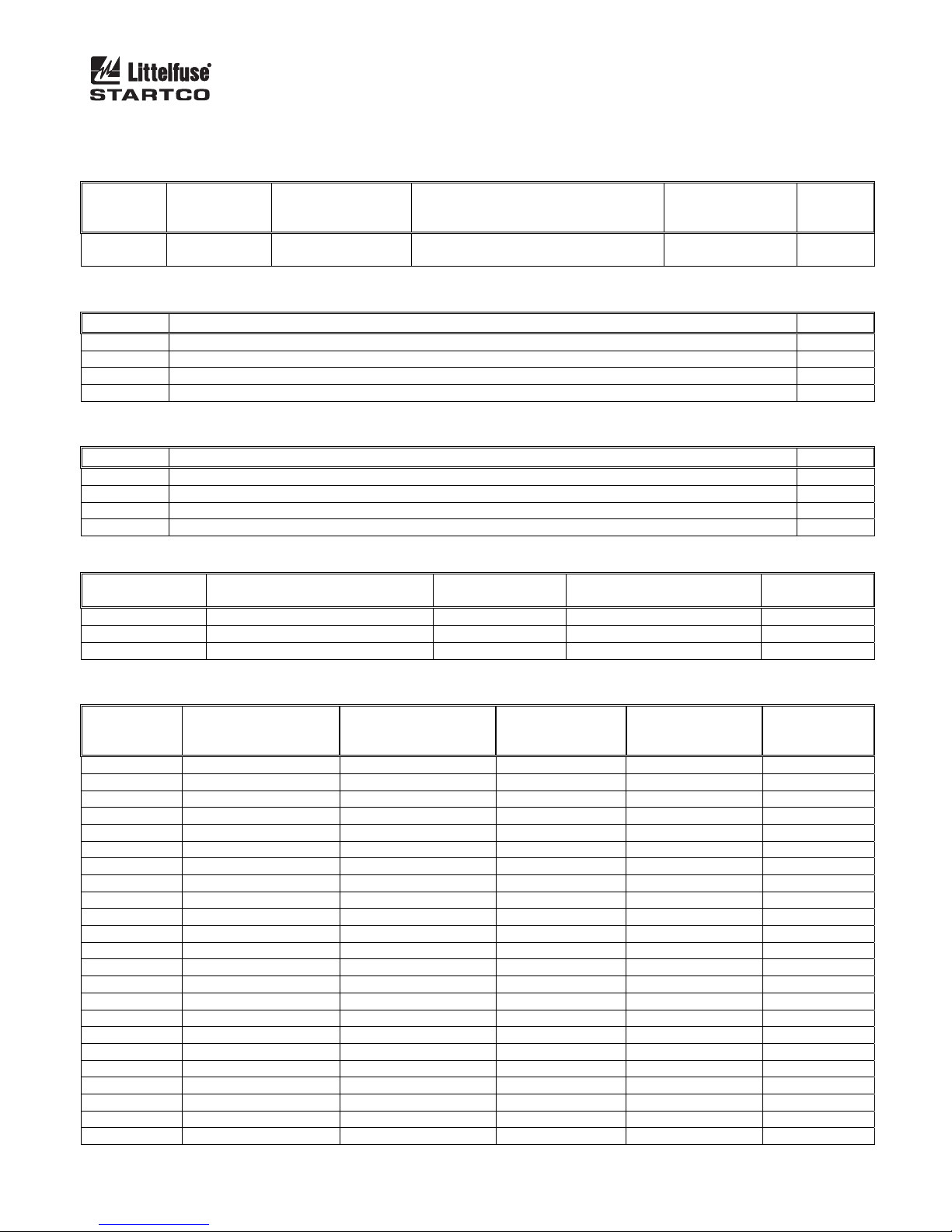
TABLE 1. EL731 DEVICENET CONNECTIONS
TERMINAL DESCRIPTION
1 V -
2 CAN_L
3 SHIELD/DRAIN
4 CAN_H
5 V +
3.2 CONFIGURATION SETTINGS
The EL731 supports 125, 250, and 500 Kbit/s. The
MAC ID is adjustable from 0 to 63. The baud rate and
MAC ID are set using DeviceNet commands or the
RSNetworx Node Commissioning tool.
3.3 TERMINATION
DeviceNet requires a 120 resistor at each end of the
network.
3.4 POWER CONSUMPTION
The DeviceNet module requires 125 mA maximum
from an external 24 Vdc supply to power the driver
circuits.
3.5 EDS FILE
The EDS file is an Electronic Datasheet file that
defines the characteristics of the EL731. It is used by
configuration software such as RSNetWorx to setup the
EL731 on the network and allows DeviceNet scanners to
map EL731 I/O Data to PLC/PAC memory.
Only one I/O Polling assembly is supported,
consisting of four bytes for output and four bytes for
input. See Section 4.
3.6 LED INDICATION
Network
Status LED
DeviceNet
Interface
Module
Status LED
Retaining
Screws
FIGURE 1. LED Indicators.
TABLE 2. NS - NETWORK STATUS LED
STATE DESCRIPTION
Steady Off Not Online / No Power
Steady Green Online, One Or More
Connections Are Established
Flashing Green Online, No Connections
Established
Steady Red Critical Link Failure
Flashing Red One Or More Connections
Timed-Out
Alternating Red/Green Self Test
NOTE: A test sequence is performed on this LED during
startup.
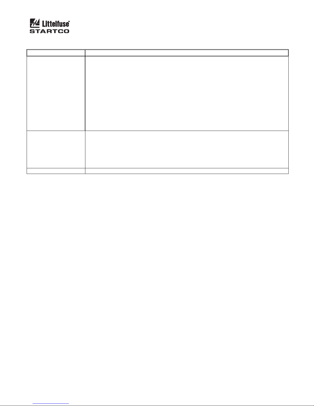
TABLE 3. MS - MODULE STATUS LED
STATE DESCRIPTION
Steady Off No Power
Steady Green Operating In Normal Condition
Flashing Green Missing Or Incomplete
Configuration, Device Needs
Commissioning
Steady Red Unrecoverable Fault(s)
Flashing Red Recoverable Fault(s)
Alternating Red/Green Self Test
NOTE: A test sequence is performed on this LED during
startup.

Page 2
EL731 DeviceNet Interface Rev. 0-B-121614
4. CLASSES
Assembly Class (4), Instance (0) Attributes
ATTRIBUTE
NUMBER ATTRIBUTE
NAME SERVICES DESCRIPTION DEFAULT,
MINIMUM,
MAXIMUM
DATA
TYPE
1
0x01 Revision Get_Attribute_Single Revision of this object. 1, 1, 1 UINT
Assembly Class (4), Instance (100), Attribute (3)
BYTE DESCRIPTION TYPE
0 Trip State T12
1
2 Alarm State T13
3
Assembly Class (4), Instance (150), Attribute (3)
BYTE DESCRIPTION TYPE
0 CT1 Enable T3
1 Command Register T14
2 CT2 Enable T3
3 Command Register T14
Application Data Class (162), Instance (0) Attributes
ATTRIBUTE
NUMBER ATTRIBUTE
NAME SERCVIES VALUE DATA
TYPE
1 Revision Get 1 UINT
2 Max Instance Get 76 UINT
3 Number Of Instances Get 76 UINT
Application Data Class (162)
INSTANCE
NUMBER ATTRIBUTE 1
NAME ATTRIBUTE 2
DATA TYPE
ATTRIBUTE 3
NUMBER OF
ELEMENTS
ATTRIBUTE 4
SERVICES ATTRIBUTE 5
VALUE
1 Model Code UINT16 1 Get T1
2 Firmware Revision UINT16 1 Get T1
3 Serial Number UINT32 1 Get T2
4 Model Option UINT32 1 Get T2
5 Reserved Get
6 CT1 Enable UINT16 1 Get/Set T3
7 CT1 Primary Turns UINT16 1 Get/Set T1
8 CT1 Trip Time UINT32 1 Get/Set T2
9 CT1 Trip Level UINT32 1 Get/Set T2
10 Reserved Get
11 CT1 Alarm Level UINT32 1 Get/Set T2
12 CT1 Calibrate UINT16 1 Set T4
13 Reserved Get
14 Reserved Get
15 CT2 Enable UINT16 1 Get/Set T3
16 CT2 Primary Turns UINT16 1 Get/Set T1
17 CT2 Trip Time UINT32 1 Get/Set T2
18 CT2 Trip Level UINT32 1 Get/Set T2
19 Reserved Get
20 CT2 Alarm Level UINT32 1 Get/Set T2
21 CT2 Input Filter UINT16 1 Get/Set T5
22 Reserved Get
23 Reserved Get

Page 3
EL731 DeviceNet Interface Rev. 0-B-121614
Application Data Class (162) (continued)
INSTANCE
NUMBER ATTRIBUTE 1
NAME ATTRIBUTE 2
DATA TYPE
ATTRIBUTE 3
NUMBER OF
ELEMENTS
ATTRIBUTE 4
SERVICES ATTRIBUTE 5
VALUE
24 Reserved Get
25 Reserved Get
26 PTC Trip Action UINT16 1 Get/Set T3
27 PTC Alarm Action UINT16 1 Get/Set T3
28 Reserved Get
29 Reserved Get
30 RTD Trip Action UINT16 1 Get/Set T3
31 RTD Trip Level UINT32 1 Get/Set T2
32 RTD Alarm Action UINT16 1 Get/Set T3
33 RTD Alarm Level UINT32 1 Get/Set T2
34 Reserved Get
35 Reserved Get
36 Relay 1 Function UINT16 1 Get/Set T6
37 Relay 1 Mode UINT16 1 Get/Set T7
38 Relay 2 Function UINT16 1 Get/Set T6
39 Relay 2 Mode UINT16 1 Get/Set T7
40 Relay 3 Function UINT16 1 Get/Set T6
41 Relay 3 Mode UINT16 1 Get/Set T7
42 Reserved Get
43 Reserved Get
44 Analog Out CT Select UINT16 1 Get/Set T8
45 Analog % Select UINT16 1 Get/Set T3
46 Output Filter UINT16 1 Get/Set T3
47 Reserved Get
48 Reserved Get
49 Temp. Sensor UINT16 1 Get/Set T10
50 Reserved Get
51 Reserved Get
52 Display Filter UINT16 1 Get/Set T3
53 Reserved Get
54 Reserved Get
55 CT1 Current SINT32 1 Get T11
56 CT2 Current SINT32 1 Get T11
57 Full Current SINT32 1 Get T11
58 Internal Temp. SINT32 1 Get T11
59 PTC Temp. SINT32 1 Get T11
60 RTD Temperature SINT32 1 Get T11
61 Reserved Get
62 Reserved Get
63 Clear Counters UINT16 1 Set T4
64 Load Defaults UINT16 1 Set T4
65 Restart System UINT16 1 Set T4
66 Reserved Get
67 Reserved Get
68 Trip State UINT16 1 Get T12
69 Alarm State UINT16 1 Get T13
70 Trip Counter UINT16 1 Get T1
71 Alarm Counter UINT16 1 Get T1
72 System Uptime UINT32 1 Get T2
73 Reserved Get
74 Reserved Get
75 Running Time (s) UINT32 1 Get T2
76 External Reset UINT16 1 Set T4

Page 4
EL731 DeviceNet Interface Rev. 0-B-121614
Attribute Data Types
ATTRIBUTE TYPE
1 Short String
2
USINT
0 = Boolean
1 = Signed 8 Bit Integer
2 = Signed 16 Bit Integer
3 = Signed 32 Bit Integer
4 = Unsigned 8 Bit Integer
5 = Unsigned 16 Bit Integer
6 = Unsigned 32 Bit Integer
3 USINT
4 USINT
5 Type Is Defined by Attribute 2
Attribute 5 Data Format
TYPE DESCRIPTION
T1 16-Bit Integer
T2 32-Bit Unsigned Integer
T3 0 = Disable
1 = Enable
T4 Command
1 = Send Command
T5
CT2 Input Filter
0 = None
1 = Full Range
2 = 90 Hz Low Pass
3 = 190 Hz High Pass
4 = 3 kHz Low Pass
T6
Relay Functions
0 = Trip
1 = Alarm
2 = Watchdog
3 = Current
T7 Relay Mode
0 = Non-Fail-Safe
1 = Fail-Safe
T8
Analog Out CT Select
0 = CT1
1 = CT2
2 = Both CT’s
T9 Analog % Level
0 = 0 – 5A Normal Mode
1 = 0 – Trip Level (% Trip Level Mode)
T10
Temp. Sensor
0 = Disabled
1 = RTD Sensor
2 = PTC Sensor
T11 32-Bit Signed Integer, (High) Bits 31..16, (Low) Bits 15..0

Page 5
EL731 DeviceNet Interface Rev. 0-B-121614
Attribute 5 Data Format (continued)
TYPE DESCRIPTION
T12
Trip Status
Bit0: 1 = System Running
Bit1: 1 = Trip Current CT1
Bit2: 1 = Trip Current CT2
Bit3: 1 = Trip User Test
Bit4: 1 = Trip CT1 Detect
Bit5: 1 = Trip CT2 Detect
Bit6: 1 = Trip NVRAM Error
Bit7: 1 = Calibrate
Bit8: 1 = Calibrate Init
Bit9: 1 = Trip Calibrate
Bit10: 1 = Trip PTC Sensor
Bit11: 1 = Trip RTD Sensor
Bit12: 1 = System Disabled
T13
Alarm Status
Bit0: 1 = No Alarms
Bit1: 1 = CT1 Current
Bit2: 1 = CT2 Current
Bit3: 1 = PTC Sensor
Bit4: 1 = RTD Sensor
Bit5: 1 = System Disabled
T14 Command Register: Sends Command when Charged from 0 to 3.

Page 6
EL731 DeviceNet Interface Rev. 0-B-121614
APPENDIX A
EL731 DEVICENET INTERFACE REVISION HISTORY
MANUAL RELEASE DATE MANUAL REVISION
December 16, 2014 0-B-121614
July 9, 2014 0-A-070914
MANUAL REVISION HISTORY
REVISION 0-B-121614
S
ECTION 4
Attribute 5 data format, T13 (Bit0) updated.
REVISION 0-A-070914
Initial release.

Mouser Electronics
Authorized Distributor
Click to View Pricing, Inventory, Delivery & Lifecycle Information:
Littelfuse:
AC700-CUA-01
Other manuals for EL731
1
Table of contents