LK Minishunt M60n User manual

1 (10)
Table of contents
Design 1
Supplied with product 1
Accessories 1
LK Minishunt M60n, Overview 2
Function and requirements 3
Assembly 3
Installation cabinets 5
Start up 5
Circulationspump 7
Troubleshooting 9
Technical data 9
Flow chart 9
Dimensions drawing 10
Design
LK Minishunt M60n is a shunt group intended for use
when smaller underoor heating areas are to be con-
nected to an existing heating system. LK Minishunt
M60n adapts the heating system temperature to the
lower temperature necessary for the underoor heat-
ing system. Its capacity can normally be set at a heat-
ing need of 50 W/m² to a maximum 60 m² underoor
heating area. Capacity is however dependent on pri-
mary temperature, pressure, laying method etc.
• For underoor heating areas up to 60 m2.
• Compact design.
• Energy efcient circulation pump.
• Thermostat-controlled maximum limit of supply
temperature.
• Switchable between single or twin pipe systems.
• VF valve.
• Easy lling & air bleeding.
• Expandable to 2, 3 or 4 underoor heating cir-
cuits.
Supplied with product
• Circulation pump Wilo Para RSB 15/6 SC, with
automatic speed control.
• Thermostat with capillary tube sensor, length 2 m.
• Thermometer to place in one of the shunt group's
thermometer pockets.
• Hose 0.5 m for air bleeding.
• Primary connector ¾" EuroCone and 2 connectors
for CU15.
• Bracket.
Accessories
• Accessories for the primary connector include
connectors for CU12 mm and PEX-/PAL pipes
dim. 16x2, 20x2 and 20x2.8.
• The LK Elbow Pipes M60n for connecting the
primary connector when the feed pipe is from
below or above. The elbow pipes enables compact
assembly.
• Connection couplings for underoor heating
pipes dim. 8, 12, 16 and 20 mm.
• The LK Mini Manifold for 2, 3 or 4 underoor
heating circuits.
• Installation cabinets for built-in or wall mounting,
see heading Installation cabinets.
• The LK Heater 350 is an electric comfort heater
for underoor heating installations using the
LK Minishunt M60n. The electric heating car-
tridge output is 350W and is sufcient under
normal conditions for underoor heated areas
up to 12 m².
LK Minishunt M60n circulation pump
Wilo Para RSB 15/6 SC
EN.33.C.204.2022-02-10
Assembly instructions | LK Minishunt M60n

2 (10)
12. Temperature limiter (TEMP). Maximum
limit for feed temperature to underoor
heating. Factory setting at 45 ºC.
13. Bracket.
14. VF valve (dim. 8 mm hex) only used in
installations with low available drive pres-
sure from the primary side of the circulation
pump.
15. Return valve (V1) for closing the primary
side's return (dim. 8 mm hex).
16. Connector return underoor heating ½"
female.
17. Air bleeding/lling valve ½" for lling the
system during installation. The cover can
be used to manoeuvre the valve.
18. Switch between single or twin pipe system.
The Minishunt is supplied set for a twin
pipe system. You can switch to a single
pipe system by screwing out the valve cone
(hex 8 mm) until the desired temperature is
reached to the radiators.
19. Primary return connection ¾" EuroCone.
Connection couplings for 15 mm CU are
supplied.
20. Thermometer pocket to measure the pri-
mary return temperature.
21. Primary feed connection ¾" EuroCone.
Connection couplings for 15 mm CU are
supplied.
LK Minishunt M60n, overview
1. The LK Elbow Pipes M60n (accessory)
for connecting the primary connector when
the feed pipe is from below or above. The
elbow pipes enables compact assembly.
2. Thermometer pocket to measure the
primary supply temperature.
3. LK Valve Housing.
4. Thermostat with capillary tube connected
room sensor, length 2 m.
5. Supply valve (V2) for shutting off/
adjusting feed/ow of underoor heating
(dim. 8 mm hex).
6. Thermometer and thermometer pocket for
measuring the underoor heating's supply
temperature. A thermometer is supplied
and can be placed/moved to the thermo-
meter pocket of your choice.
7. Air bleeding valve with hose nipple.
Hose 0.5 m is supplied.
8. Circulation pump, Wilo Para RSB 15/6 SC
with automatic speed control.
9. Electrical connection of the circulation
pump, see heading Electrical connection
of circulation pump.
10. Connector feed underoor heating ½",
female.
11. LK Mini Manifold (accessory) for connec-
ting 2, 3 or 4 underoor heating circuits
dim. 8, 12, 16 or 20 mm.
EN.33.C.204.2022-02-10
Assembly instructions | LK Minishunt M60n
8
79
10
11
2019
18
1716
15
14
12
13
21
5
4
3
2
1

3 (10)
Function and requirements
In order for the correct operation of the LK Mi-
nishunt M60n and underoor heating system,
the existing heating system must be tted with a
circulation pump and weather dependent supply
temperature. The LK Minishunt M60n adapts the
heating system temperature to the lower tempe-
rature necessary for the underoor heating sys-
tem. The heating system must before assembly be
ushed through and must not contain any impu-
rities or additives that can damage the product.
Assembly
The LK Minishunt M60n must be mounted at a
higher level than the underoor heating installa-
tion in order to assist air bleeding. When choo-
sing a suitable location for installation, pay atten-
tion to any possible structure-borne noise. The
shunt group should preferably be placed in a spe-
cially designed cabinet in accordance with indu-
stry practices, see heading Installation cabinets.
Pipe connection
The minishunt's primary connection is tted with
an external ¾" EuroCone thread. Pipe connection
to the primary side is made using the enclosed
ttings for 15 mm CU. Accessories include con-
nectors for CU12 mm and PEX-/PAL pipes dim.
16x2, 20x2 and 20x2.8 . LK Elbow Pipes M60n (ac-
cessory) facilitates assembly when the feed pipe
is from below or above and needs to be angled
into the shunt group. The minishunt's underoor
heating connections have ½" females. A single
underoor heating circuit is connected using LK
Connection Coupling ½" male for pipe dim. 8, 12,
16 or 20 mm directly to the minishunt. For more
circuits, the LK Mini Manifold is used to connect
2, 3 or 4 circuits to pipe dim. 8, 12, 16 or 20 mm.
Electrical connection of circulation pump
Electrical connection of the pump must be carried
out by a qualied electrician in accordance with
applicable regulations. The pump is tted with a
xed 3-core cable and a Wilo-connector with in-
tegrated strain relief. The Wilo-connector repla-
ces the requirements for a 2-pole circuit breaker.
Connect the supply cable L, N, PE to the Wilo-
connector according to the following picture se-
quence. The electrical connection must be fused
with Max. 10 A slow blow fuse.
Note!
Before any maintenance/repair work the pump power
supply must be disconnected. Motor protection for the
circulation pump is not required.
Assembly of electrical connection
1.
32 mm
7 mm
2.
PE
L
N
3. 4.
Click!
5. 6.
Dismantling electrical connection
1
2
3
EN.33.C.204.2022-02-10
Assembly instructions | LK Minishunt M60n

4 (10)
Assembly of supplied thermostat
To install the supplied thermostat, unscrew the
hand wheel and assemble the thermostat then.
The capillary tube connected sensor is preferably
placed on an interior wall.
1. Unscrew the hand wheel.
2. Remove the hand wheel.
3. Assemble the thermostat.
4. Screw on the hand wheel.
Assembly of LK Actuator
Wireless or wired electronic room control for the
LK Minishunt M60n are available as accessories.
The enclosed thermostat is then replaced with an
electric LK Actuator and is installed according to
the picture sequence.
1. Unscrew the hand wheel.
2. Remove the hand wheel.
3. Remove the adapter using a screw driver.
4. Click the adapter that is supplied with
actuator into place, and assemble the
actuator then.
EN.33.C.204.2022-02-10
Assembly instructions | LK Minishunt M60n

5 (10)
Installation cabinets
The installation can be concealed using specially
designed cabinets in accordance with industry
practices. Cabinets are available for either built-
in or wall mounting. The cabinets are made from
1 mm powder coated steel plate and have a sea-
led base with rubber pipe inlets. The base of the
cabinet is tted with an outlet for leakage indi-
cation so that any leakage water can be drained.
LK Minishunt M60n assembled in LK Minishunt
Cabinet M60n XL.
Article no. Name Intended for
243 53 70 LK Shunt Cabinet M60n LK Minishunt M60n
243 53 69 LK Shunt Cabinet M60n
XL
LK Minishunt M60n
with assembled LK
Mini Manifold, or LK
Heater 350
243 53 67 LK Frame/hatch M60n
INB
Built-in LK Shunt
Cabinet M60n VT
243 46 80 LK Frame/hatch UFH INB Built-in LK Shunt
Cabinet M60n XL
243 53 68 LK Frame/hatch M60n
UTV
Wall mounted LK
Shunt Cabinet
M60n
243 46 81 LK Frame/hatch UFH
UTV
Wall mounted LK
Shunt Cabinet
M60n XL
188 13 02 LK Base M60n Wall mounted LK
Shunt Cabinet
M60n
243 53 72 LK Base M60n XL Wall mounted LK
Shunt Cabinet
M60n
Start up
Air bleeding
Flush through the system with hydraulic pres-
sure in order to air bleed it and remove any im-
purities. The circulation pump should be turned
off during this work, follow the process described
below:
1. Close against the primary side using the
thermostat valve pos. 4. Continue to close
the primary side's return by checking that
the switch valve from single to twin pipe
system pos. 18 is screwed in and that the
primary return valve V1 pos. 15 is closed.
2. Close the valve V2 pos. 5.
3. Ensure that the VF valve pos. 14 is fully
open.
4. Assemble the hose connection to the lling
valve pos. 17.
5. Flush the oor heating side via the lling
valve pos. 17 and air bleed/drain through
the air bleed valve pos. 7 until the water
runs clear.
6. Close the air bleed valve pos. 7 and lling
valve pos. 17 and disassemble the hose
connection.
7. Open the primary side by resetting the
thermostat valve pos. 4 and open the
valve V2 pos. 5.
8. Air from the primary side can now be
bled out via the air vent pos. 7.
9. Open the return valve V1 pos. 15. If the
minishunt is connected to a single pipe
radiator system the switch for single or
twin pipe system pos. 18 should be ad-
justed.
10. Start the circulation pump and use the
pump's automatic venting routine to
remove accumulated air in the pump.
See heading Circulation pump.
EN.33.C.204.2022-02-10
Assembly instructions | LK Minishunt M60n

6 (10)
Adjustment
As the LK Minishunt M60n is intended for con-
nection to existing heating systems, the available
drive pressure and ow on the primary side are
often unknown. Without this information the
theoretical adjustment values of the minishunt
cannot be calculated. Adjustment should then be
carried out as described below.
If the available drive pressure and ow on the
primary side are known, the theoretical adjust-
ment for the minishunt can be calculated, refer
to the Project planning and design guidance for
LK Underoor heating.
1. Carry out air bleeding of the oor heating
system and the minishunt, as shown above.
2. Start the circulation pump. Upon start up,
use the pump's automatic venting routine
to remove accumulated air in the pump.
The automatic venting routine starts after 3
seconds and proceeds for 10 min. The ven-
ting routine is indicated with a fast ashing
green diode light.
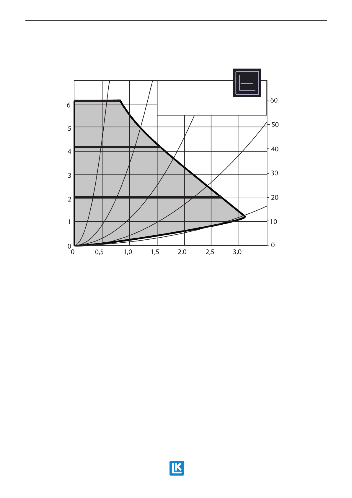
After completing the venting process, the
constant pressure curve that best matches
the requirements of the system is chosen,
see the capacity chart.
3. Set the switch 2/1 pos. 18 for single or twin
pipe radiator systems (twin pipe radiator
system is factory set at delivery). For single
pipe systems the valve is gradually ope-
ned until the correct heating capacity and
temperature is achieved to the following
radiators.
4. Set the primary temperature from the hea-
ting source to the minishunt temporarily to
approx. 55 °C.
5. Set the temperature limiter TEMP to pos. 12
in accordance with the table below. Normal
setting is about 45 ºC.
6. Set the thermostat valve pos. 4 in accord-
ance with the table below.
7. Allow the system to stabilise for about 10
min. The feed temperature should now be
35-45 ºC.
NOTE!
If the temperature is too low, see
Troubleshooting. Note that at start up a
system in an unheated concrete slab,
can take up to 24 hours before the feed
temperature has reached the correct level.
NOTE!
If the temperature is too high, adjust
the feed temperature using the temperature
limiter pos.12 in accordance with the table
below.
8. Finish by resetting the primary temperature
from the heat source to normal temperature.
Settings for the temperature limiter (TEMP)
For limiting the feed temperature for underoor
heating.
Settings for the tempera-
ture limiter (TEMP)
Max. temperature
0 22 ºC
1 25 ºC
2 35 ºC
3 40 ºC
4 45 ºC
5 55 ºC
Settings for the thermostat with a capillary
tube connected sensor
Settings for the thermo-
stat
Room temperature
1 8 ºC
2 14 ºC
3 20 ºC
4 26 ºC
5 32 ºC
Circulation pump
The circulation pump has automatic speed con-
trol, which reduces power consumption and gi-
ves a quieter operation as the pump adjusts the
ow according to the requirements of the system.
A cast arrow on the pump housing indicates the
direction of the ow.
EN.33.C.204.2022-02-10
Assembly instructions | LK Minishunt M60n

7 (10)
For underoor heating it is recommended that the
pump is set to constant pressure control. Choose
the constant pressure curve that best matches the
requirements of the system, see capacity chart.
Ensure that the pump never runs dry and the
system is well vented before use. Use the pump´s
automatic venting routine at start up.
Setting the pump function selector
Wilo Para RSB 15/6 SC set to the default factory setting.
The green push button is used for changing the
settings. See the Quick Guide from Wilo's site.
Automatic venting routine
When the oor heating system is lled, ushed
and vented the circulation pump can be started.
At start up, use the pump's automatic venting
routine to remove accumulated air in the pump's
rotor chamber.
The automatic venting routine starts after 3 se-
conds and proceeds for 10 min. The venting rou-
tine is indicated with a fast ashing green diode
light.
After completing venting, choose the constant
pressure curve that best matches the require-
ments of the system, see capacity chart below. If
no choice is made, the pump operation automati-
cally switches to constant pressure with max. ca-
pacity. See the Quick Guide from Wilo's site.
Settings for the automatic venting routine.
Constant pressure curve
For underoor heating it is recommended that
the pump is set to constant pressure control.
Choose the constant pressure curve that best
matches the requirements of the system, see the
capacity chart.
The symbol for constant pressure.
Wilo Para RSB 15/6 SC set to constant pressure.
Proportional pressure curve
Proportional pressure setting is normally not
used for underoor heating.
The symbol for proportional pressure.
EN.33.C.204.2022-02-10
Assembly instructions | LK Minishunt M60n

8 (10)
Capacity chart
Capacity chart LK Minishunt M60n V2 with Wilo Para
RSB 15/6 SC.
Troubleshooting
The underfloor heating circuit does not
get warm
• Check that the Thermostat pos. 4 is set to
desired room temperature.
• Check that the shut-off valves pos. 5 (V2)
and pos. 15 (V1) are open.
• Check that the setting on the temperature limiter
pos. 12 (TEMP) is correct, see table Settings for
the temperature limiter.
• Check the connection, operation and setting of
the circulation pump.
If the above adjustments have been performed and
there is still no heat reaching the underoor heating
circuit, this can be an indication of low available drive
pressure from the primary side. Begin by checking
that the circulation pump of the primary side can be
stepped up.
EN.33.C.204.2022-02-10
Assembly instructions | LK Minishunt M60n
∆p-c (Constant)
H/mp/kPa
Q/m³/h
Wilos Para
15/6, 25/6, 30/6
1 −230 V −Rp ½, Rp 1, Rp 1¼
∆p-c
max
I
II
III
If this does not rectify the situation, the circulation
pump of the minishunt can help to ”draw” the water
from the primary side to the underoor heating side
by gradually closing (clockwise) the VF valve pos. 14
(VF) until the correct temperature has been achieved.
Return temperature of the underfloor heating
circuit is too low
• Open the supply valve pos. 5 (V2).
• Increase the speed of the circulation
pump using the function selector.
The radiators after the minishunt do not get
warm for single pipe radiator systems
The LK Minishunt M60n is supplied in the twin pipe
design. For the single pipe system, switching will need
to be carried out, see heading Start up and adjustment.

9 (10)
Technical data
Article number 243 52 15
Max. operating pressure 0.6 MPa
Max. pressure dierential
in operation.
0.1 MPa
Operational temperature
secondary
+12 - +55 ºC
Operational temperature
primary
Max. 80 ºC
Ambient temperature Max. +60 ºC
Circulation pump Wilo Para RSB 15/6 SC
Voltage 1 phase 230 V AC +10%/-
15% 50/60 Hz, PE
Output Max. 43 W
Current Max. 0.44 A
Cable protection class IP X4D
Insulation class F
Max. valve capacity Kvs 1.05
Max. valve capacity with
self-acting thermostat at
the maximum setting.
At room temperature
approx. 20 ºC.
Kv 0.9
Approved pump CE, EC Low Voltage Di-
rective (2006/95/ EC) incl.
additions
EN.33.C.204.2022-02-10
Assembly instructions | LK Minishunt M60n
Flow diagram
2/1 TEMP
A
18
12
5
8
4
14
15
B
VF
V2
V1
2/1
TEMP
A
18
12
5
8
4
14
15
B
VF
V2
V1
A. Primary side with main pump.
B. Secondary side underoor heating system.
18. Switching from twin to single pipe system
(2/1).
4. Control valve with thermostat and room
sensor.
15. Isolation valve (V1) primary return.
12. Temperature limiter (TEMP). Max. limit for
feed temperature to underoor heating.
5. Supply valve (V2) for shutting off/adjusting
feed/ow of underoor heating .
8. Circulation pump.
14. VF Valve.

10 (10)
Dimensions drawing
Right
Left
EN.33.C.204.2022-02-10
Assembly instructions | LK Minishunt M60n
LK Systems AB, Box 66, 161 26 Bromma | www.lksystems.se
Table of contents
Other LK Water Pump manuals
Popular Water Pump manuals by other brands

EBARA
EBARA WINNER Operating and maintenance manual

Stübbe
Stübbe ETL Series operating manual

Pentair
Pentair MYERS MSK75 Installation and operator's manual

Spowdi
Spowdi Pro MKII manual

Grundfos
Grundfos PS.R Series Installation and operating instructions

PROCESSTEC
PROCESSTEC ViscoTwin 130 Series instruction manual

MYERS
MYERS BP5 owner's manual

Bizon Pumps
Bizon Pumps BPN-330C installation instructions

Stuart Turner
Stuart Turner Showermate U2.6 bar Single Installation, operation & maintenance instructions

Pentair
Pentair SHURFLO 4029-110-X02 Installation & operation manual

Lincoln
Lincoln CENTRO-MATIC 84944 manual

Wilo
Wilo BM Installation and operating instructions