ELECTRICAL REQUIREMENTS
- Be certain you connect the unit to the proper power supply.
- Using incorrect voltage will cause server damage to the motor.
- The voltage requirement is printed on the serial number label.
- All pump models are supplied with a junction box and cover.
- To reduce the risk of electric shock, be certain that a grounding conductor is
connected to the green grounding located inside the junction box.
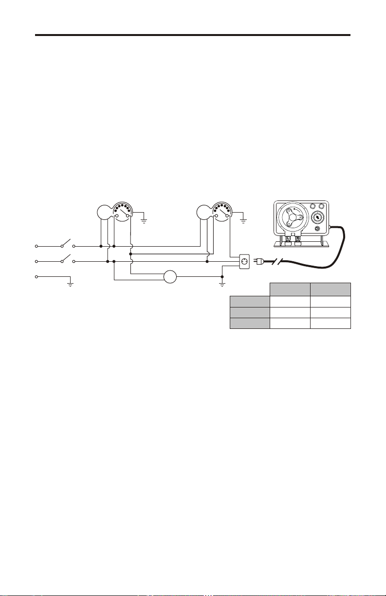
The electrical hook up is very important to operation. The injector must never
operate when treated line is shut down. The diagram above shows th injector
wired within a cycle of a circulation pump or any system where chemical is
used within a cycle but does or does not run al full system. If your system is
complicated, be sure your electrician knows what is required. Remember
chemicals fed to a stopped system can ruin it.
The pump is designed to perform in a wide variety of installations. However, the
service life of the pump will vary, depending on many factors such as; fluid ,
temperature, pressure, etc. Because of the wide variety of installations, the pump
has been factory tested for pressure and performance using water only. Do not
use chemicals if you are not satisfied they are compatible with the pumps
construction.
The pump tube assemblies are designed for maximum service life. However, the
service life can be adversely affected by the chemicals used, the amount of back
pressure, the motor R.P.M., and temperature.
The pump tube assemble should be inspected frequently. Replace the tube if any
cracking, leaking or loss of feed rate occurs.
THREADLESS AND THREADED INJECTORS
The most common problem is calcium and/or lime build up inside the injector, foot valve
and tubing. This is basic material and can easily be removed by running a weak
solution of muriatic acid through it. After flushing the pump with clear water, place the
injector filling and foot valve with the tubing attached in a container of weak (1-5)
solution of commercial grade muriatic, them pump it around and around. After flushing
out the wetted parts with clear water again, return pump to service. CAUTION do not
allow acid and chlorine products to come together. This is VERY DANGEROUS to your
health!
OUTPUT ADJUSTMENTS
The pause control knob adjusts the cycle timer’s time on. The model A-100 standard
cycle timer is set at one minute. Other cycle lengths are available. To adjust the
amount of time on, turn the pause control knob to the correct setting. ½ equals
approximately 30 seconds on. 3/4 equals approximately 45 seconds on, etc.
MEASURING THE OUTPUT
SUPPLY TANK FOR CHEMICALS
Plastic containers must be designed and manufactured for this purpose. Your
container must be designed for whatever chemical you are using. Do not
place the container in direct sunlight. Ultraviolet (UV) rays attack many
materials which can cause them to become brittle.
OPERATION - MAINTENANCE
Once every week inspect tubing, and accessory valves and fittings. Inspect
all parts for signs of leaks, swelling, cracking, corrosion or discoloration. Also,
inspect the tubing for elasticity.
Cracking, crazing, discoloration, etc., during the first week of operation are
signs of severe chemical attack. If this occurs, immediately remove the fluid
from the injector. Determine which parts are being attacked and replace with
parts that have been manufactured using more suitable material.
NOTE: Sketches and Diagrams for information only. Qualified personnel,
must be used when altering the electrical cord in any way. Qualified
personnel, must also be used for installation of mechanical connections.
Injector
Common
Hot
Ground
M M
M
Time Clocks
Breaker
Switches
Ground
Circulation
Pump
Injector Motor Wire Color Code
HOT
COMMON
GROUND
Black
White
Green
Brown
Blue
Green-Yellow
USA
115V 60HZ
Europe
220V 50HZ
Note: On CE models, wiring will have
double pole - single throw switches
A-100 Page 4 A-100
Page 5
RECOMMENDTUBECHANGE WHEN DISPLAY BLINKS
ADJUSTMENT
CYCLETIME
TUBELIFEWARNING TIMER
RESET
99SEC.CYCLE
PRIME
Suction
Tubing
Discharge
Tubing
Graduated
Container
(not provided)
Blue-White
Injection Fitting
Pump
Blue-WhiteR
This volumetric test will take into account
installation factors such as line pressure,
fluid velocity, specific gravity, etc. This
test is the most accurate for measuring
the injector’s output in an individual
installation.
1. With the injector installed under
normal operating conditions, place the
foot valve/strainer in a large graduated
container.
2. Fill the container with the chemical to
be injected and run the unit until all air is
removed from the suction line.
3. Refill the container, if necessary, and
with the foot valve in the solution, not the
amount of chemical in the container.
4. Run the injector for a measured
amount of time and note the amount of
chemical injected.


