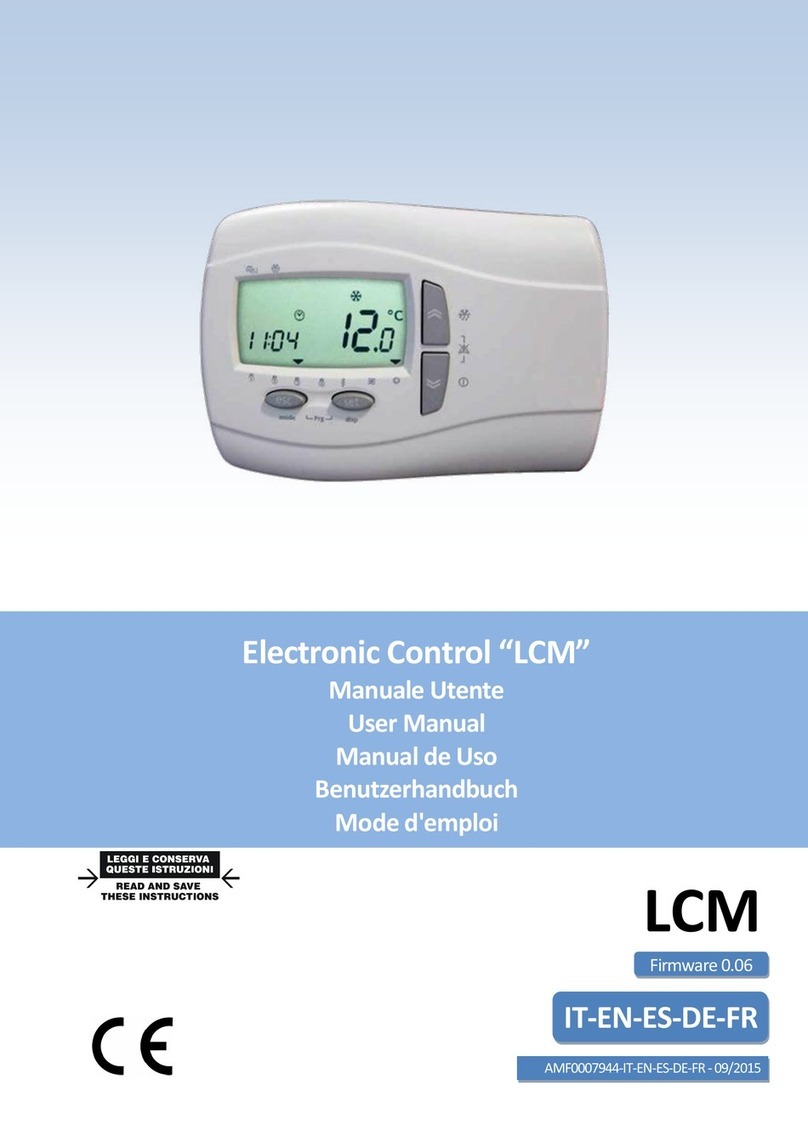
LMF Clima LCE User manual

Electronic Control LCE
Manuale Utente
User Manual
Benutzerhandbuch
LCE
IT-EN-DE
MC00003_04-IT-EN-DE - 10/2015
Le unità regolate
Units regulated
Unidades reguladas
Einheiten geregelt
RKB
RKE 3V
RKE-BP
RKH
RKS 3V
Firmware 2.4
True life inside
airandwaterhandling
foraconfortablelife

Light Electronic Control LCE Manuale Utente
Light control manual-ITA-neutro_03.docx Rev. 04 IT 1/ 6
firmware 2.4
IT
Specifiche controllo:
Selezione automatica / manuale delle velocità
Gestione valvola freddo / promiscua
Gestione valvola calda
Gestione resistenza ON-OFF
Post ventilazione
Gestione serranda free-cooling
Gestione allarmi
oErrore sonda
oSurriscaldamento resistenza
oAllarme filtro sporco
Programmazione settimanale
ON-OFF remoto
Display remoto con sensore interno
Logica di controllo
Nei seguenti diagrammi viene illustrata la logica di controllo estiva-invernale
Heating
Heating logic
Ventilation
+
2°C
Tsp-Te
Tsp-Treg
Cooling logic
Ventilation
By-pass
+ By-pass
Cooling
2°C
Tsp-Te
Tsp-Treg
Cooling modulation
By-pass
Cooling modulation
+
Heating modulation
Ventilation
2°C
1°C
1°C
Heating
Heating modulation
+ By-pass
By-pass
2°C
Ventilation
Cooling
By-pass
0.5°C
0.5°C
Treg = temperatura sonda di regolazione (di mandata o ambiente su display remoto)
Tsp = temperatura di set point
Te = temperatura sonda aria esterna

Light Electronic Control LCE Manuale Utente
Light control manual-ITA-neutro_03.docx Rev. 04 IT 2/ 6
firmware 2.4
IT
Programmazione settimanale
Per ogni giorno della settimana è possibile scegliere tra 4 programmi:
Programma P1: l’uità viee accesa i due fasce orarie ad esepio ua al attio e ua alla sera
Programma P2: l’uità viee accesa i ua sola fascia oraria
Programma P3: l’uità viee accesa tutto il giorno
Programma P4: l’uità viee speta tutto il gioro
Display
Icone:
A3-A6: Programma settimanale attivo
A7-A10: Velocità ventilatore
A11: ON: OFF manuale
LAMPEGGIANTE: OFF da programma settimanale
A12, A13, A15: modo operativo / durante settaggio: set visualizzato
A16: ON: allarme attivo
LAMPEGGIANTE: allarme riamabile
A17: Free cooling / Free heating attivo
A19: Ora visualizzata
A29-A35: Giorno della settimana
On-Off
On-Off è gestito nei seguenti modi:
Off da ingresso digitale ha priorità su tutto
Off da tastiera remota:
1) Se le fasce orarie sono disabilitate, l'on/off da tastiera remota è definitivo
2) Se le fasce orarie sono abilitate, l'on/off da tastiera remota è temporaneo fino al successivo
evento (in questo caso il profilo selezionato lampeggia). Il set utilizzato è l’ultio selezioato
dalle fasce orarie. In caso di black-out l’uità riparte co le fasce orarie.
Off da BMS via MODBUS
Off da fasce orarie

Light Electronic Control LCE Manuale Utente
Light control manual-ITA-neutro_03.docx Rev. 04 IT 3/ 6
firmware 2.4
IT
Tastiera
Pressione breve:
Set orologio
Pressione lunga:
Cambio On/Off
Pressione lunga:
Abilita disabilita fasce orarie
Pressione breve:
Cambio velocità ventilatore
Pressione lunga:
Cambio modo
Pressione breve:
Menù setpoint
e allarme.
Pressione breve:
Menù ““
Pressione lunga:
Temperatura esterna
giorni della settimana (1= lunedì)
Lista Menu Prg
Premere isiee Esc e “et
Prof: in questa sezione vi sono le impostazioni per la programmazione settimanale:
oST1: ora inizio 1° fascia 1° programma
oEN1: ora fine 1° fascia 1° programma
oSE1 (estate): set-point 1° fascia 1° programma
oSE1 (inverno): set-point 1° fascia 1° programma
oST2: ora inizio 2° fascia 1° programma
oEN2: ora fine 2° fascia 1° programma
oSE2 (estate): set-point 2° fascia 1° programma
oSE2 (inverno): set-point 2° fascia 1° programma
oST: ora inizio 2° programma
oEND: ora fine 2° programma
oSET (estate): set-point 2° programma
oSET (inverno): set-point of 2° programma
Day: in questa sezione si associa il giorno al programma
oMon: Programma Lunedì, possibili valori
P1 l’uità viee accesa i due fasce orarie
P2 l’uità viee accesa i una sola fasce orarie
P3 l’uità viee accesa tutto il gioro
P4 l’uità viee speta tutto il gioro
oTue: Programma Martedì
oWed: Programma Mercoledì
oThu: Programma Giovedì
oFri: Programma Venerdì
oSat: Programma Sabato
oSun: Programma Domenica
Auto: Set cambio modo estate inverno
oSAUT: Set cambio modo estate inverno in automatico da temperatura esterna
odAUT: Differenziale cambio modo estate inverno in automatico da temperatura esterna

Light Electronic Control LCE Manuale Utente
Light control manual-ITA-neutro_03.docx Rev. 04 IT 4/ 6
firmware 2.4
IT
Serv: in questa sezione si va a configurare il controllo
oPWD: in serire password per service (1)
oPcfg: configurazione impianto
0= sistema a 2 tubi, batteria unica promiscua
1= sistema a 2 tubi, batteria fredda + resistenza
2= sistema a 4 tubi, batteria fredda + batteria calda
oRprop: sonda di regolazione
0= sonda mandata aria
1= sonda interna al display
Menu Set
Premere Set
Set-point estivo manuale
Set-point invernale manuale
Cartella allarmi:
oEr01: Errore sonda di regolazione:
L’uità viee speta
Allarme a riarmo automatico
oEr02: Allarme sonda aria esterna:
Free-cooling disattivato
Allarme a riarmo automatico
oEr03: Errore sonda Display:
“e Rprop= l’uità viee speta
“e Rprop= l’allare o viee visualizzato
oEr04: Allarme filtro sporco:
Sola visualizzazione
oEr05: Surriscaldamento resistenza elettrica:
Resistenza disattivata
Ventilatori attivati
Modbus
Tipo di modbus Holding Register
Commando di lettura: 03 (03Hex)
Commando di scrittura: 16 (10Hex)
Come modificare i protocolli di comunicazione Modbus:
collegarsi via Modbus tramite la RS-485 con i protocolli di default:
indirizzo= 1
baud rate= 9600
parità= EVEN
Bit di dati= 8 (non modificabile)
Bit di stop= 1 (non modificabile)
modificare secondo le necessità i protocolli ai seguenti indirizzi:
53274= indirizzo (1-255)
53275= baud rate
3= 9600 baud (default)
4= 19200 baud
5= 38400 baud
6= 58600 baud
7= 115200 baud
53276= parità
1= EVEN (default)
2= NONE
3= ODD
per memorizzare è necessario riavviare il dispositivo.
Esempio cablaggio rete
Cable
Grigio: GND
Bianco: +
Nero: -

Light Electronic Control LCE Manuale Utente
Light control manual-ITA-neutro_03.docx Rev. 04 IT 5/ 6
firmware 2.4
IT
1.1. Variabili utente:
MODBUS Tipo: HOLDING REGISTER
Commando di lettura: 03 (03Hex)
Commando di scrittura: 16 (10Hex)
Indirizzo
Scrittura/Lettura
Descrizione MOD BUS
Valore
Um
Default
Min
Max
53274
Modbus protocol controller address
1
1
1
255
53275
Modbus baud rate protocol
3= 9600 baud (default)
4= 19200 baud
5= 38400 baud
6= 58600 baud
7= 115200 baud
3
3
3
7
53276
Modbus parity protocol
1= EVEN (default)
2= NONE
3= ODD
1
1
1
3
Indirizzo
Scrittura/Lettura
Descrizione SET
Valore
Um
Default
Min
Max
16389
3 Point Valve Cooling
Proportional Band
2
°C
20
1
100
16390
3 Point Valve Heating
Proportional Band
2
°C
20
1
100
16391
Fan Auto:
Differential Medium Speed
2
°C
20
1
100
16392
Fan Auto:
Differential Maximum Speed
2
°C
20
1
100
16393
Heater Differential
2
°C
20
1
100
16394
Heater Post Ventilation Time
60
Sec
60
10
500
16395
FreeCooling Differential
1
°C
10
1
100
16396
FreeHeating Differential
1
°C
10
1
100
16397
Free Cooling Hysteresis
0.5
°C
5
1
15
16398
Cambio modo:
0 = Cool; 1 = Heat; 2 = Auto
2
2
0
2
16399
Stato On Off (Memorized into
EEprom)
0 = Off; 1 = On
0
0
0
1
16400
Controllo ventilatore
0 = Min; 1 = Med; 2 = Max; 3 =
Auto
3
3
0
3
16401
Setpoint Freddo
26.0
°C
260
50
350
16402
Setpoint Caldo
20.0
°C
200
50
350
16403
Profilo 1: Inizio banda 1
08:00
HH:MM
480
0
Profilo 1: Fine Banda 1
16404
Profilo 1: Fine banda 1
12:00
HH:MM
720
Profilo 1: Inizio banda 1
1439
16405
Profilo 1: Inizio banda 2
14:00
HH:MM
840
0
Profilo 1: Fine Banda 2
16406
Profilo 1: Fine banda 2
17:00
HH:MM
1020
Profilo 1: Inizio banda 2
1439
16407
Profilo 2: Inizio banda
08:00
HH:MM
480
0
Profilo 2: Fine Banda
16408
Profilo 2: Fine banda
17:00
HH:MM
1020
Profilo 2: Inizio banda
1439
16409
Profilo 1: Set Banda Freddo 1
26.0
°C
260
Profilo 1: Set Banda Caldo 1
350
16410
Profilo 1: Set Banda Freddo 2
26.0
°C
260
Profilo 1: Set Banda Caldo 2
350
16411
Profilo 2: Set Banda Freddo
26.0
°C
260
Profilo 2: Set Banda Caldo
350
16412
Profilo 1: Set Banda Caldo 1
20.0
°C
200
50
Profilo 1: Set Banda Freddo 1
16413
Profilo 1: Set Banda Caldo 2
20.0
°C
200
50
Profilo 1: Set Banda Freddo 2

Light Electronic Control LCE Manuale Utente
Light control manual-ITA-neutro_03.docx Rev. 04 IT 6/ 6
firmware 2.4
IT
16414
Profilo 2: Set Banda Caldo
20.0
°C
200
50
Profilo 2: Set Banda Freddo
16415
Selezione Profilo Lunedì
1 = P1; 2 = P2; 3 = P3; 4 = P4
1
1
1
4
16416
Selezione Profilo Martedì
1 = P1; 2 = P2; 3 = P3; 4 = P4
1
1
1
4
16417
Selezione Profilo Mercoledì
1 = P1; 2 = P2; 3 = P3; 4 = P4
1
1
1
4
16418
Selezione Profilo Giovedì
1 = P1; 2 = P2; 3 = P3; 4 = P4
1
1
1
4
16419
Selezione Profilo Venerdì
1 = P1; 2 = P2; 3 = P3; 4 = P4
1
1
1
4
16420
Selezione Profilo Sabato
1 = P1; 2 = P2; 3 = P3; 4 = P4
2
2
1
4
16421
Selezione Profilo Domenica
1 = P1; 2 = P2; 3 = P3; 4 = P4
4
4
1
4
16422
Abilitazione Profilo
0 = Off; 1 = On
0
0
0
1
16423
Setpoint antigelo (rev 2.1)
5.0
°C
50
-50
150
16424
Differenziale antigelo (rev 2.1)
1.0
°C
10
1
50
Indirizzo Lettura
Descrizione Ingressi-Uscite
Valore
Um
Default
Min
Max
8192
State On-Off digital input (DI1)
0 = On; 1 = Off
0
0
0
1
8960
Sonda temperatura di regolazione
17.5
°C
0
-500
1100
8961
Velocità attuale del ventilatore
0 = Off; 1 = Min; 2 = Med; 3 = Max
0
0
0
3
8962
Posizione valvola tre vie fredda o
promiscua
0.0
%
0
0
1000
8963
Posizione valvola tre vie caldo
0.0
%
0
0
1000
8964
Stato batteria elettrica
0 = Off; 1 = On
0
0
0
1
8965
Stato serranda Bypass
0 = Off; 1 = On
0
0
0
1
8966
Temperatura esterna
11.2
°C
0
-500
1100
8968
Stato On Off
0
0
0
1
Indirizzo Lettura
Descrizione
Allarmi
0= Non attivo
1= Attivo
2=Reset manuale
Valore
Um
Default
Min
Max
9000
Errore sonda temperatura di
regolazione
0
0
0
1
9001
Errore sonda temperatura esterna
0
0
0
1
9002
Errore sonda temperatura tastiera
0
0
0
1
9003
Allarme filtri ostruiti
0
0
0
1
9004
Allarme batteria elettrica (Reset
Manuale)
0
0
0
2
9005
Allarme antigelo (rev 2.1)
0
0
0
1
Indirizzo Lettura
Descrizione Versione
Valore
Um
Default
Min
Max
9471
Versione applicativo (Software)
2.1
21
Note:
(diviso 10, °C) dividere il valore per 10, il risultato sarà in gradi centigradi con una cifra decimale (Es: 175= 17.5°C)
(diviso 10, %) dividere il valore per 10, il risultato sarà in percentuale con una cifra decimale (Es: 505= 50.5%)
(HH:MM) minuti a partire da mezzanotte dove 0= 00:00 e 1439= 23:59 (Es: 120= 02:00; 1170= 19:30)

Light Electronic Control DzLCEdzUser Manual
Light control manual-ENG-neutro_03.docx Rev. 04 EN 1/ 6
firmware 2.4
EN
Control features:
Automatic / Manual 3 speed fan
3 point cooling / changeover floating valve
3 point heating floating valve
ON-OFF Electric heater
Post ventilation
Free cooling - Free heating damper
Alarm management and diagnostic
oSensor failure
oHeater over temperature
oDirty filter alarm
Clock program management
Remote ON-OFF
Remote display with internal sensor
Control logic
In the following diagrams is explained the summer-winter control logic
Heating
Heating logic
Ventilation
+
2°C
Tsp-Te
Tsp-Treg
Cooling logic
Ventilation
By-pass
+ By-pass
Cooling
2°C
Tsp-Te
Tsp-Treg
Cooling modulation
By-pass
Cooling modulation
+
Heating modulation
Ventilation
2°C
1°C
1°C
Heating
Heating modulation
+ By-pass
By-pass
2°C
Ventilation
Cooling
By-pass
0.5°C
0.5°C
Treg = regulation probe temperature
Tsp = Set point temperature
Te = External probe temperature

Light Electronic Control DzLCEdzUser Manual
Light control manual-ENG-neutro_03.docx Rev. 04 EN 2/ 6
firmware 2.4
EN
Weekly program
For each day of the week it is possible to select between 4 programs:
Program P1: the unit is turned ON in two different time range (for example one in the morning and
one in the afternoon)
Program P2: the unit turned ON in a single time range
Program P3: the unit is turned ON all the day
Program P4: the unit is turned OFF all the day
Display
Icons:
A3-A6: Active weekly program
A7-A10: Fan speed
A11: ON: Manual OFF
BLINKING: Weekly program OFF
A12, A13, A15: Working mode / while setting: visualizing set point
A16: ON: active alarm
BLINKING: resettable alarm
A17: Freecooling/Freeheating
A19: Clock time viewing
A29-A35: Day of the week
On-Off
The unit can be turned On-Off in the following way:
Off by digital input, main priority
Off by Remote keyboard:
1) While weekly program is not active, the unit is definitively On/Off
2) While weekly program is active, the unit can be temporarily turned On/Off till next event (in case
of this the active profile led blinks). The set point is the same of the last time range. In case of
blackout the unit restarts with the weekly program activated.
Off by BMS via MODBUS
Off by weekly program

Light Electronic Control DzLCEdzUser Manual
Light control manual-ENG-neutro_03.docx Rev. 04 EN 3/ 6
firmware 2.4
EN
Keyboard
Short press:
Fan speed change
Short press:
Clock Set
Long press:
Toggle On/Off
Long press:
Enable / disable clock program
Short press:
Setpoint and
alarm menu
Long press:
Actual setpoint
Short press:
menu
days of the week (1 = Monday)
Long press:
Summer / winter
change
Menu Prg List
Press together utto Es ad “et
Prof: in this section there are the settings for the weekly program
oST1: start time of1st range of 1st program
oEN1: end time of 1st range of 1st program
oSE1 (summer): set-point of 1st range of 1st program
oSE1 (winter): set-point of 1st range of 1st program
oST2: start time of 2nd range of 1st program
oEN2: end time of 2nd range of 1st program
oSE2 (summer): set-point of 2nd range of 1st program
oSE2 (winter): set point of 2nd range of 1st program
oST: start time of 2nd program
oEND: end time of 2nd program
oSET (summer): set-point of 2nd program
oSET (winter): set-point of 2nd program
Day: i this setio there’s the progra assiget for each day
oMon: Monday program, possible value
P1 the unit is turned ON in two different time range
P2 the unit turned ON in a single time range
P3 the unit is turned ON all the day
P4 the unit is turned OFF all the day
oTue: Tuesday program
oWed: Wednesday program
oThu: Thursday program
oFri: Friday program
oSat: Saturday program
oSun: Sunday program
Auto: Automatic summer/winter changeover parameters
oSAUT: Fresh air temperature set point for automatic changeover
odAUT: Season changeover differential

Light Electronic Control DzLCEdzUser Manual
Light control manual-ENG-neutro_03.docx Rev. 04 EN 4/ 6
firmware 2.4
EN
Serv: in this section there is the controller configuration
oPWD: insert service password (1)
oPcfg: plant configuration
0= 2 pipes system, unique changeover coil
1= 2 pipes system, cooling coil + electric heater
2= 4 pipes system, cooling coil + heating coil
oRprop: regulation probe
0= supply air sensor
1= display sensor
Menu Set List
Press button Set
Manual summer set-point
Manual winter set-point
Alarm folder:
oEr01: Regulation sensor failure; effects:
The unit is turned off
Automatic reset alarm
oEr02: External air sensor failure; effects:
Free-cooling mode disabled
Automatic reset alarm
oEr03: Display sensor failure; effects:
If Rprop=1 the unit is turned off
If Rprop=0 alarm not shown
oEr04: Dirty filter alarm; effect
None
oEr05: Electric heater over-temperature; effects:
Electric heater disabled
Fan activated
Modbus
Modbus type Holding Register
Read command: 03 (03Hex)
Write command: 16 (10Hex)
To modify the modbus communication protocols do as follows:
connect via Modbus through the RS-485 port with default protocols:
address= 1
baud rate= 9600
parity= EVEN
Word length= 8 (not editable)
Stop bits= 1 (not editable)
modify as you need the protocols writing the following address:
53274= address (1-255)
53275= baud rate
3= 9600 baud (default)
4= 19200 baud
5= 38400 baud
6= 58600 baud
7= 115200 baud
53276= parity
1= EVEN (default)
2= NONE
3= ODD
To activate the changes reboot the controller.
Net wiring example
Cable
Gray: GND
White: +
Black: -

Light Electronic Control DzLCEdzUser Manual
Light control manual-ENG-neutro_03.docx Rev. 04 EN 5/ 6
firmware 2.4
EN
1.1. User variables:
MODBUS Point Type: HOLDING REGISTER
Read command: 03 (03Hex)
Write command: 16 (10Hex)
Address
write/read
Description
MODBUS
Value
Um
Default
Min
Max
53274
Modbus protocol controller
address
1
1
1
255
53275
Modbus baud rate protocol
3= 9600 baud (default)
4= 19200 baud
5= 38400 baud
6= 58600 baud
7= 115200 baud
3
3
3
7
53276
Modbus parity protocol
1= EVEN (default)
2= NONE
3= ODD
1
1
1
3
Address
write/read
Description
SET
Value
Um
Default
Min
Max
16389
3 Point Valve Cooling
Proportional Band
2
°C
20
1
100
16390
3 Point Valve Heating
Proportional Band
2
°C
20
1
100
16391
Fan Auto:
Differential Medium Speed
2
°C
20
1
100
16392
Fan Auto:
Differential Maximum Speed
2
°C
20
1
100
16393
Heater Differential
2
°C
20
1
100
16394
Heater Post Ventilation Time
60
Sec
60
10
500
16395
FreeCooling Differential
1
°C
10
1
100
16396
FreeHeating Differential
1
°C
10
1
100
16397
Free Cooling Hysteresis
0.5
°C
5
1
15
16398
User Working Mode:
0 = Cool; 1 = Heat; 2 = Auto
2
2
0
2
16399
On Off Status (Memorized into
EEprom)
0 = Off; 1 = On
0
0
0
1
16400
Fan Control
0 = Min; 1 = Med; 2 = Max; 3 =
Auto
3
3
0
3
16401
Setpoint Cooling
26.0
°C
260
50
350
16402
Setpoint Heating
20.0
°C
200
50
350
16403
Profile 1: Start band 1
08:00
HH:MM
480
0
Profile 1: End band 1
16404
Profile 1: End band 1
12:00
HH:MM
720
Profile 1: Start band 1
1439
16405
Profile 1: Start band 2
14:00
HH:MM
840
0
Profile 1: End band 2
16406
Profile 1: End band 2
17:00
HH:MM
1020
Profile 1: Start band 2
1439
16407
Profile 2: Start band
08:00
HH:MM
480
0
Profile 2: End band
16408
Profile 2: End band
17:00
HH:MM
1020
Profile 2: Start band
1439
16409
Profile 1: Set Cool Band 1
26.0
°C
260
Profile 1: Set Heat Band 1
350
16410
Profile 1: Set Cool Band 2
26.0
°C
260
Profile 1: Set Heat Band 2
350
16411
Profile 2: Set Cool Band
26.0
°C
260
Profile 2: Set Heat Band
350
16412
Profile 1: Set Heat Band 1
20.0
°C
200
50
Profile 1: Set Cool Band 1

Light Electronic Control DzLCEdzUser Manual
Light control manual-ENG-neutro_03.docx Rev. 04 EN 6/ 6
firmware 2.4
EN
16413
Profile 1: Set Heat Band 2
20.0
°C
200
50
Profile 1: Set Cool Band 2
16414
Profile 2: Set Heat Band
20.0
°C
200
50
Profile 2: Set Cool Band
16415
Monday Profile Selection
1 = P1; 2 = P2; 3 = P3; 4 = P4
1
1
1
4
16416
Tuesday Profile Selection
1 = P1; 2 = P2; 3 = P3; 4 = P4
1
1
1
4
16417
Wednesday Profile Selection
1 = P1; 2 = P2; 3 = P3; 4 = P4
1
1
1
4
16418
Thursday Profile Selection
1 = P1; 2 = P2; 3 = P3; 4 = P4
1
1
1
4
16419
Friday Profile Selection
1 = P1; 2 = P2; 3 = P3; 4 = P4
1
1
1
4
16420
Saturday Profile Selection
1 = P1; 2 = P2; 3 = P3; 4 = P4
2
2
1
4
16421
Sunday Profile Selection
1 = P1; 2 = P2; 3 = P3; 4 = P4
4
4
1
4
16422
Profile Enabled
0 = Off; 1 = On
0
0
0
1
16423
Antifreeze Setpoint (rev 2.1)
5.0
°C
50
-50
150
16424
Antifreeze Differential (rev 2.1)
1.0
°C
10
1
50
Address
read
Description
Input-Output
Value
Um
Default
Min
Max
8192
State On-Off digital input (DI1)
0 = On; 1 = Off
0
0
0
1
8960
Regulation Sensor Temperature
17.5
°C
0
-500
1100
8961
Current Fan Speed
0 = Off; 1 = Min; 2 = Med; 3 = Max
0
0
0
3
8962
Three Point Cold or Changeover
Valve Estimated Position
0.0
%
0
0
1000
8963
Three Point Hot Valve Estimated
Position
0.0
%
0
0
1000
8964
Heater Status
0 = Off; 1 = On
0
0
0
1
8965
External Bypass Status
0 = Off; 1 = On
0
0
0
1
8966
Fresh Air Temperature
11.2
°C
0
-500
1100
8968
On Off Status
0
0
0
1
Address
read
Description
Allarm
0= Not Active
1= Active
2=Manual Reset
Value
Um
Default
Min
Max
9000
Suplpy Air Sensor Error
0
0
0
1
9001
Fresh Air Sensor Error
0
0
0
1
9002
SKW Display Sensor Error
0
0
0
1
9003
Filter Alarm
0
0
0
1
9004
Heater Overheating Alarm
(Manual Reset)
0
0
0
2
9005
Antifreeze Alarm (rev 2.1)
0
0
0
1
Address
read
Description
Version
Value
Um
Default
Min
Max
9471
Application version
2.1
21
Note:
(divided 10, °C) divide the value by 10, the result is in degree Celsius with one decimal place (Es: 175= 17.5°C)
(divided 10, %) divide the value by 10, the result is in percentage with one decimal place (Es: 505= 50.5%)
(HH:MM) minutes starting from midnight where 0= 00:00 e 1439= 23:59 (In example: 120= 02:00; 1170= 19:30)

Light Electronic Control LCE Benutzerhandbuch
Light-control manual-DE Rev. 04 DE 1/ 6
firmware 2.4
DE
EE
Steuerungen:
Automatischer/ manueller 3 Geschwindigkeiten Lüfter
3-PunktKühlung/ Wechselventil
3-Punkt Heizung Schwimmerventil
ON-OFF Elektroheizer
Nachlüftung
Free Cooling/Free HeatingSchieber
Alarmmanagement und-diagnose
oFehler Temperaturfühler
oÜberhitzung Heizer
oAlarm verschmutzter Filter
Uhr-Programmierung
ON-OFF Fernbedienung
Fernanzeige auf Display mit Innensensor
Steuerlogik
In den folgenden Diagrammen wirden die Sommer-Winter Steuerlogik gezeigt
Heating
Heating logic
Ventilation
+
2°C
Tsp-Te
Tsp-Treg
Cooling logic
Ventilation
By-pass
+ By-pass
Cooling
2°C
Tsp-Te
Tsp-Treg
Cooling modulation
By-pass
Cooling modulation
+
Heating modulation
Ventilation
2°C
1°C
1°C
Heating
Heating modulation
+ By-pass
By-pass
2°C
Ventilation
Cooling
By-pass
0.5°C
0.5°C
Treg = Regulierung Messtemperatur
Tsp = Eingestellte Temperatur (Set Point)
Te = gemessene Außentemperatur

Light Electronic Control LCE Benutzerhandbuch
Light-control manual-DE Rev. 04 DE 2/ 6
firmware 2.4
DE
EE
Wochenprogrammierung
Man kann für jeden Tag der Woche aus 4 Programmen vorwählen:
Programm P1: Das Gerät wird zu zwei Zeitbereichen eingeschaltet(Z. B. am Morgen und am Abend)
Programm P2: Das Gerät wird nur zu einem Zeitbereich eingeschaltet
Programm P3: Das Gerät bleibt den ganzen Tag eingeschaltet
Programm P4: Das Gerät bleibt den ganzen Tag ausgeschaltet
Bildschirmanzeige
Ikonen:
A3-A6: Wochenprogramm aktiviert
A7-A10: Geschindigkeit Ventilator
A11: ON: Handeinstellung OFF
BLINKEND: Wochenprogramm OFF
A12, A13, A15: Betriebsmodus / während Einstellung: Anzeige der Set Points
A16: ON: Alarm aktiviert
BLINKEND: Alarmzurücksetzbar
A17: FreeCooling/ Free Heating aktiviert
A19: Uhrzeit-Anzeige
A29-A35: Wochentag
Ein-Aus
Die Ein-Aus wird auf folgende Weise verwaltet:
Aus den digitalen Eingang hat Vorrang vor allen
Aus von Remote-Tastatur:
1) Wenn die Zeitschlitze deaktiviert sind, ist der Ein / Aus durch Ferntastatur endgültige
2) Wenn die Zeitschlitze aktiviert ist, ist das Ein / Aus von Fernbedien bis zum nächsten Ereignis (in
diesem Fall das ausgewählte Profil blinkt) vorübergehend. Der verwendete Satz der letzten
Zeitschlitze ausgewählt. Im Falle eines Stromausfalls startet das Gerät mit den Bändern.
Aus BMS über Modbus
Aus Zeitbänder

Light Electronic Control LCE Benutzerhandbuch
Light-control manual-DE Rev. 04 DE 3/ 6
firmware 2.4
DE
EE
Tastatur
Short press:
Fan speed change
Short press:
Clock Set
Long press:
Toggle On/Off
Long press:
Enable / disable clock program
Short press:
Setpoint and
alarm menu
Long press:
Actual setpoint
Short press:
menu
days of the week (1 = Monday)
Long press:
Summer / winter
change
Menüprogrammliste
Gleichzeitig Esc und “etdrücken
Prof: In diesem Abschnitt finden Sie die Einstellungen für die Wochen-Programmierung
oST1: Uhrzeit Beginn 1. Zeitbereich 1. Programm
oEN1: Uhrzeit Ende 1. Zeitbereich 1. Programm
oSE1 (Sommer): Set Point 1.Zeitbereich 1. Programm
oSE1 (Winter): Set Point 1. Zeitbereich 1. Programm
oST2: Uhrzeit Beginn 2. Zeitbereich 2. Programm
oEN2: Uhrzeit Ende2. Zeitbereich 2. Programm
oSE2 (Sommer): Set Point 2. Zeitbereich 2. Programm
oSE2 (Winter): Set Point 2. Zeitbereich 2. Programm
oST: UhrzeitBeginn 2. Programm
oEND: UhrzeitEnde 2. Programm
oSET (Sommer): Set Point 2. Programm
oSET (Winter): Set Point 2. Programm
Day: In diesem Abschitt finden Sie die Programmzuweisung für jeden Tag
oMon: ProgrammMontag, mögliche Werte
P1 Das Gerät wird zu zwei Zeitbereichen eingeschaltet
P2 Das Gerät wird nur zu einem Zeitbereich eingeschaltet
P3 Das Gerät bleibt den ganzen Tag eingeschaltet
P4 Das Gerät bleibt den ganzen Tag ausgeschaltet
oTue: Programm Dienstag
oWed: Programm Mittwoch
oThu: Programm Donnerstag
oFri: Programm Freitag
oSat: Programm Samstag
oSun: Programma Sonntag
Auto: Sollwert Modus-Schalter Sommer Winter
oSAUT: Sollwert-Modus automatisch an Sommer Winter Außentemperatur
odAUT: Differential-Modus Schalt automatisch von Sommer-Winter-Outdoor-Temperatur

Light Electronic Control LCE Benutzerhandbuch
Light-control manual-DE Rev. 04 DE 4/ 6
firmware 2.4
DE
EE
Serv:In diesem Abschnitt wird die Steuerung konfiguriert
oPWD: Service-Passwort eingeben (1)
oPcfg: Konfiguration der Anlage
0=System mit 2 Leitungen, Mischspirale
1= System mt 2 Leitungen, Kühlspirale+ Heizspirale
2= System mit 4 Leitungen Kühlspirale+ Heizspirale
oRprop: Regelfühler
0= Luftfühler
1= Bildschirmsensor
Menü-Einstellung
Setdrücken
Set Point Sommer Handbetrieb
Set PointWinter Handbetrieb
Alarmliste:
oEr01: Fehler Regelfühler:
Gerät schaltet sich aus
Automatische Zurücksetzung des Alarms
oEr02: Alarm Luftfühler:
Free Cooling deaktiviert
Automatische Zurücksetzung des Allarms
oEr03: Fehler Bildschirmsensor:
Bei Rprop=1 wird das Gerät ausgeschaltet
Bei Rprop=0 wird der Alarm nichtauf dem Bildschirm angezeigt
oEr04: Alarm verschmutzter Filter:
Alarm wir nur angezeigt
oEr05: Überhitzung Elektroheizer:
Elektroheizer deaktiviert
Ventilatoren aktiviert
Modbus
Modbus Typ: Holding Register
Lesebefehl: 03 (03Hex)
Schreibbefehl: 16 (10Hex)
Wie man die Kommunikationsprotokolle Modbus verändert:
Verbinden Sie sich über Modbus und RS-485 mit den Standardprotokollen:
Adresse= 1
Baud-Rate= 9600
Parität= EVEN
Bitbreite= 8 (nicht editierbar)
Stop bits= 1 (nicht editierbar)
Verändern Sie die Protokolle an den folgenden Adressen nach Ihrenm Bedarf:
53274= Adresse (1-255)
53275= Baud-Rate
3= 9600 Baud (Standard)
4= 19200 Baud
5= 38400 Baud
6= 58600 Baud
7= 115200 Baud
53276= Parität
1= EVEN (Standard)
2= NONE
3= ODD
Das Gerät muss neu gestartet werden , um die Änderungen zu speichern.
Beispiel Kabelnetz
Supervisor
Gerät 1
Gerät 2
Gerät 3
Gerät n
Kabel
Grau: GND
Weiss: +
Schwarz: -

Light Electronic Control LCE Benutzerhandbuch
Light-control manual-DE Rev. 04 DE 5/ 6
firmware 2.4
DE
EE
1.1. Benutzervariablen:
MODBUS Point Typ: HOLDING REGISTER
Lesebefehl: 03 (03Hex)
Schreibbefehl: 16 (10Hex)
Adresse
schreiben/lesen
Beschreibung
MODBUS
Wert
Um
Standard
Min
Max
53274
Modbus
Protokoll Controller Adresse
1
1
1
255
53275
Modbus Baud-Rate Protokoll
3= 9600 Baud (Standard)
4= 19200 Baud
5= 38400 Baud
6= 58600 Baud
7= 115200 Baud
3
3
3
7
53276
Modbus Parität Protokoll
1= EVEN (Standard)
2= NONE
3= ODD
1
1
1
3
Adresse
schreiben/lesen
Beschreibung
SET
Wert
Um
Standard
Min
Max
16389
3 Point Ventil Kühlung
Proportionalband
2
°C
20
1
100
16390
3 Point Ventil Heizen
Proportionalband
2
°C
20
1
100
16391
Automatische Lüfter:
Durchschnittsgeschwindigkeit
Differenz
2
°C
20
1
100
16392
Automatische Lüfter:
Maximaler Differenzgeschwindigkeit
2
°C
20
1
100
16393
Heizung Differenz
2
°C
20
1
100
16394
Heizung Nachlüftung Zeit
60
Sec
60
10
500
16395
Freecooling Differenz
1
°C
10
1
100
16396
FreeHeating Differenz
1
°C
10
1
100
16397
Free Cooling Hysterese
0.5
°C
5
1
15
16398
Benutzer Arbeitmodus:
0 = cool; 1 = heatHeiß; 2 = Auto
2
2
0
2
16399
On Off Status (gespeichert in EEprom)
0 = Off; 1 = On
0
0
0
1
16400
Lüftersteuerung
0 = Min; 1 = Med; 2 = Max; 3 = Auto
3
3
0
3
16401
Set Point Kühlung (Cooling)
26.0
°C
260
50
350
16402
Set Point Heizung (Heating)
20.0
°C
200
50
350
16403
Profil 1: Start band 1
08:00
HH:MM
480
0
Profil 1: End band 1
16404
Profil 1: End band 1
12:00
HH:MM
720
Profil 1: Start band 1
1439
16405
Profil 1: Start band 2
14:00
HH:MM
840
0
Profil 1: End band 2
16406
Profil 1: End band 2
17:00
HH:MM
1020
Profil 1: Start band 2
1439
16407
Profil 2: Start band
08:00
HH:MM
480
0
Profil 2: End band
16408
Profil 2: End band
17:00
HH:MM
1020
Profil 2: Start band
1439
16409
Profil 1: Set Cool Band 1
26.0
°C
260
Profil 1: Set Heat Band 1
350
16410
Profil 1: Set Cool Band 2
26.0
°C
260
Profil 1: Set Heat Band 2
350
16411
Profil 2: Set Cool Band
26.0
°C
260
Profil 2: Set Heat Band
350
16412
Profil 1: Set Heat Band 1
20.0
°C
200
50
Profil 1: Set Cool Band 1
16413
Profil 1: Set Heat Band 2
20.0
°C
200
50
Profil 1: Set Cool Band 2

Light Electronic Control LCE Benutzerhandbuch
Light-control manual-DE Rev. 04 DE 6/ 6
firmware 2.4
DE
EE
16414
Profil 2: Set Heat Band
20.0
°C
200
50
Profil 2: Set Cool Band
16415
Montag Profil Auswahl
1 = P1; 2 = P2; 3 = P3; 4 = P4
1
1
1
4
16416
Dienstag Profil Auswahl
1 = P1; 2 = P2; 3 = P3; 4 = P4
1
1
1
4
16417
Mittwoch Profil Auswahl
1 = P1; 2 = P2; 3 = P3; 4 = P4
1
1
1
4
16418
Donnerstag Profil Auswahl
1 = P1; 2 = P2; 3 = P3; 4 = P4
1
1
1
4
16419
Freitag Profil Auswahl
1 = P1; 2 = P2; 3 = P3; 4 = P4
1
1
1
4
16420
Samstag Profil Auswahl
1 = P1; 2 = P2; 3 = P3; 4 = P4
2
2
1
4
16421
Sonntag Profil Auswahl
1 = P1; 2 = P2; 3 = P3; 4 = P4
4
4
1
4
16422
Profil aktiviert
0 = Off; 1 = On
0
0
0
1
16423
Antifrost Sollwert (rev 2.1)
5.0
°C
50
-50
150
16424
Antifrost Differenzial (rev 2.1)
1.0
°C
10
1
50
Adresse
lesen
Beschreibung
Input-Output
Wert
Um
Standard
Min
Max
8192
Status On-Off Digitaler Eingang (DI1)
0 = On; 1 = Off
0
0
0
1
8960
Regelfühler
17.5
°C
0
-500
1100
8961
Aktuelle Lüftergeschwindigkeit
0 = Off; 1 = Min; 2 = Med; 3 = Max
0
0
0
3
8962
3-Punkt Kühlung oder Wechselventil
Geschätzte Position
0.0
%
0
0
1000
8963
3- Punkt Heizung Ventil Geschätzte
Position
0.0
%
0
0
1000
8964
Heizer Status
0 = Off; 1 = On
0
0
0
1
8965
Außenüberbrückung Status
0 = Off; 1 = On
0
0
0
1
8966
Außentemperatur
11.2
°C
0
-500
1100
8968
On Off Status
0
0
0
1
Adresse
lesen
Beschreibung
Alarm
0= Not Active
1= Active
2=Manual Reset
Wert
Um
Standard
Min
Max
9000
Fehler
Luftauslassfühler
0
0
0
1
9001
Fehler Außenraumfühler
0
0
0
1
9002
Fehler SKW -Fühler
0
0
0
1
9003
Filter Alarm
0
0
0
1
9004
Heizer Alarm (manuelle
Zurücksetzung)
0
0
0
2
9005
Antifrost Alarm (rev 2.1)
0
0
0
1
Adresse
lesen
Beschreibung
Version
Wert
Um
Standard
Min
Max
9471
Anwendungsversion
2.1
21
Anmerkung:
(geteilt durch 10, °C) den Wert durch 10 teilen, es wird ein Ergebnis in Celsiusgrad mit einer Kommazahl erhalten (z. B.: 175= 17.5°C)
(geteilt 10, %) den Wert durch 10 teilen, es wird ein Ergebnis in Prozent mit einer Kommazahl erhalten(z. B.: 505= 50.5%)
(HH:MM) Minuten ab Mitternacht, wobei 0= 00:00 und 1439= 23:59 bedeuten(z. B.: 120= 02:00; 1170= 19:30)

firmware 2.4
Rev. 04
A
Descrizione
Description
Beschreibung
Collegamenti
Wiring
Verdrahtung
Parametri
Parameters
Parameter
Valvola calda
Heating valve
Heißwasserventil
Esterna
Immisione
Ripresa ambiente
Espulsione
Supply
Return
Fresh air
Exhaust
N= Neutro –Neutral - Neutral
Y1= Apre –Open - Öffnen
Y2= Chiude –Close - Schließen
N
Y2
Y1
3
2
3-POINT
230Vac
1
(Password= 1)
= 2
Valvola fredda
Cooling valve
Kaltwasserventil
Esterna
Immisione
Ripresa ambiente
Espulsione
Supply
Return
Fresh air
Exhaust
N= Neutro –Neutral - Neutral
Y1= Apre –Open - Öffnen
Y2= Chiude –Close - Schließen
N
Y2
Y1
7
6
3-POINT
230Vac
1
(Password= 1)
= 2
Valvola promiscua
Unique changeover valve
Einzigartige Umschaltventil
Esterna
Immisione
Ripresa ambiente
Espulsione
Supply
Return
Fresh air
Exhaust
N= Neutro –Neutral - Neutral
Y1= Apre –Open - Öffnen
Y2= Chiude –Close - Schließen
N
Y2
Y1
7
6
3-POINT
230Vac
1
(Password= 1)
= 0
Table of contents
Languages:
Other LMF Clima Thermostat manuals
Popular Thermostat manuals by other brands

Timeguard
Timeguard TRT030DN operating instructions

Uni-Line
Uni-Line PERFECTSENSE PS2210 Series owner's manual

Pure-Pro
Pure-Pro DP711 Installation and operating instructions

Pro 1 IAQ
Pro 1 IAQ T855 installation manual

Comfort Stat
Comfort Stat CP2020 owner's manual

Water Furnace
Water Furnace IntelliZone2 ZoneStat Instruction guide