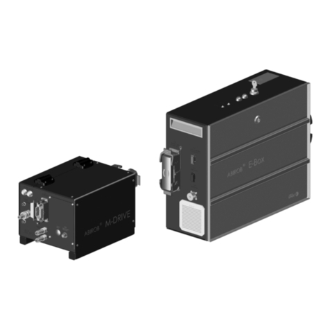
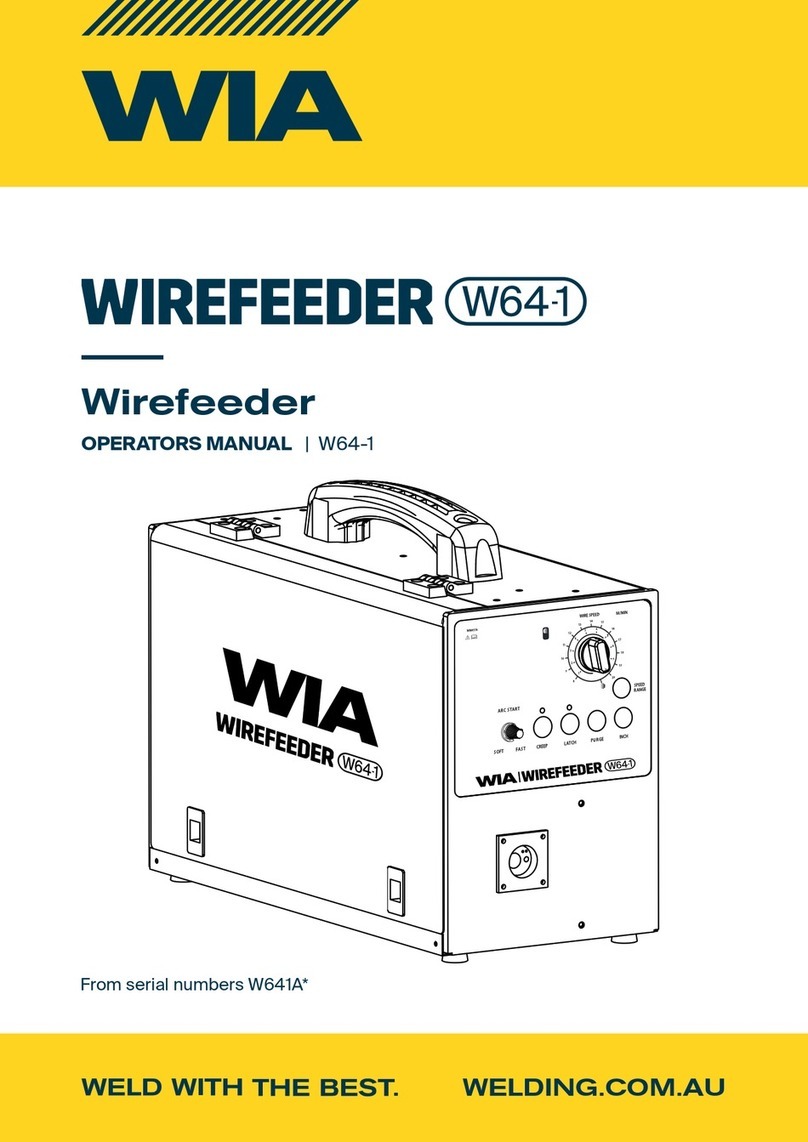
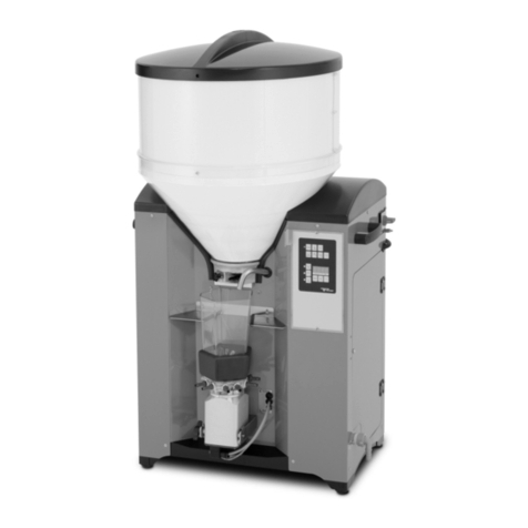
LOBSTER ARF-800P User manual

ᾒᾞᾝᾣᾔᾝᾣᾢ
ᾐᾡᾕὼ ᵖᵎᵎ ᾟ
ᵧᵬᵱᵲᵰᵳᵡᵲᵧᵭᵬᴾᵫᵟᵬᵳᵟᵪ
ᒍᛖᾔᾝᾖᾛᾘᾢᾗ
ᾐᾤᾣᾞᴾᾡᾘᾥᾔᾣᴾᾕᾔᾔᾓᾔᾡ
PRINTED IN JAPAN
Professional model of auto rivet feeder to install blind rivets.
INTRODUCTION䈈䈈䈈䈈䈈䈈䈈 䠍
㻌㻌㻌㻌㻌㻌㻌㻌㻌㻌㻌㻌㻌㻌㻌㻌㻌㻌㻌㻌㻌㻌㻌㻌㻌㻌㻌㻌㻌㻌㻌䈈䈈䈈䈈䈈䠎䚷
NOMENCLATURE䈈䈈䈈䈈䈈䈈 䠒
TECHNICAL DATA…䈈䈈䈈䈈䈈 䠓
PREPARATION BEFORE㻌 㼁㻿㻱䈈䠕
㻌㻌㻌㻌㻌㻌㻌㻌㻌㻌㻌㻌㻌㻌㻌㻌㻌㻌㻌㻌㻌㻌㻌㻌㻌㻌㻌㻌㻌䈈䈈䈈䠍䠏
䚷䚷䚷䚷䚷䚷䚷䚷䚷䚷䚷䚷䚷䚷䚷䚷㻌㻌㻌㻌㻌㻌㻌㻌㻌䠍䠐
MAINTENANCE㻌㻌䈈䈈䈈䈈䈈䈈䠍䠓
STORAGE 䡡䈈䈈䈈䈈䈈䈈䈈䈈䠍䠓
ORDERING PARTS䈈䈈䈈䈈䈈䠍䠓䚷
TROUBLESHOOTING䈈䈈䈈䈈䠍䠔
PARTS TABLE㻌䈈䈈䈈䈈䈈䈈䈈䠍䠕
IMPORTANT SAFETY
I N S T R U C T I O N S
OPERATING THE AUTO
RIVET FEEDER
PROCEDURES FOR CHANGING
RIVETS AND RIVETER
・Thank you very much for purchasing “LOBSTER” auto rivet feeder. To ensure correct operation,
please carefully read this instruction manual and keep it in a safe place for later reference.
・This is Original instructions.
Osaka 579-8053, Japan
12-8 Shijo-cho, Higashi-Osaka City
Telephone: +81(72)981-7466 Telefacs: +81(72)981-9420
URL https://www.lobtex.co.jp/
MANUFACTURER
ᵧᶌᶒᶃᶐᶌᵿᶒᶇᶍᶌᵿᶊᴾᵫᵿᶐᶉᶃᶒᶇᶌᶅᴾᵄᴾᵱᵿᶊᶃᶑᴾᵢᶇᶔᶇᶑᶇᶍᶌ

䞉This machine is a feeder to supply “LOBSTER” brand blind rivets to a vacuum type air riveter.
It is not designed, produced or sold for any other purpose.
䞉This instruction manual shows how to operate and perform maintenance and inspection in
order㻌to use safely and efficiently.
䞉Use appropriate blind rivet which are fully designed and examined to there specification and
strength.
䠍
ᾀ
䠍
ᾁ
䞉Our warranty does not apply to direct and indirect damages and lost income caused
by the misuse, abuse, and unauthorized modification of the machine.
We do not guarantee the strength or quality of blind rivet.
䞉We do not guarantee any damages and failures caused by any modifications without
䚷our written approval.
䞉We do not guarantee any damages and failures caused by use of parts other than our
䚷recommendation.
䠍
ᒍᛖᾔᾝᾖᾛᾘᾢᾗ
⅐ ※⁀⁆⁄⁁‶⁇‵⁆※⁁⁀
IMPORTANT NOTICES
INDEMNIFICATION
䞉Read this manual carefully before using this machine. Follow instructions in this manual for
䚷handling this machine, replacing accessories or replacing parts as needed.
䞉If you have any questions about this manual, check the model㻌㻔type㻕and contact the
“LOBSTER” dealer where you purchased the machine.
䞉It is impossible to foresee all potential dangers and describe them in this manual.
You must use this machine paying attention to safety as well as observing the instructions
in this manual.
䞉This manual is translated from Japanese, its original language. It is your own responsibility
to achieve a full understanding of the contents of this manual before using the equipment
described.
䞉Lobtex Co., Ltd. has the copyright of this manual. It is prohibited to publish, copy or translate
䚷to other language without prior consent.

䕺Be sure to read the following Important Safety Instructions carefully and make sure that you
understand them thoroughly before using this machine.
䠎
ᴾᴾᾀᵌᵲᶆᶃᴾᵿᶇᶐᴾᶎᶐᶃᶑᶑᶓᶐᶃᴾᶑᶆᶍᶓᶊᶂᴾᶀᶃᴾᶉᶃᶎᶒᴾᶕᶇᶒᶆᶇᶌᴾᶒᶆᶃᴾᶐᵿᶌᶅᶃᴾᶍᶄᴾᵎᵌᵓᴾᶒᶍᴾᵎᵌᵔᴾᵫᵮᵿᵌ
䞉If an air pressure which is greater than this is used, the machine may become damaged,
and injury or damage to property may result.
ᴾᴾᾁᵌᵟᶊᶕᵿᶗᶑᴾᶕᶃᵿᶐᴾᶎᶐᶍᶒᶃᶁᶒᶇᶔᶃᴾᶅᶍᶅᶅᶊᶃᶑᴾᶕᶆᶇᶊᶃᴾᶗᶍᶓᴾᶓᶑᶃᴾᶒᶆᶃᴾᶋᵿᶁᶆᶇᶌᶃᵌᴾᴾ
䞉The rivets may jump out by accident and cause injuries (e.g. blindness).
䞉Use a dust mask, safety shoes, hard hat and hearing protector appropriately to prevent
accidents and injuries.
ᴾᴾᾂᵌᵫᵿᶉᶃᴾᶑᶓᶐᶃᴾᶒᶆᵿᶒᴾᶒᶆᶃᴾᶋᵿᶁᶆᶇᶌᶃᴾᵿᶌᶂᴾᶒᶆᶃᴾᵿᶇᶐᴾᶑᶍᶓᶐᶁᶃᵊᴾᶎᶍᶕᶃᶐᴾᶁᵿᶀᶊᶃᴾᵿᶐᶃᴾᶁᶍᶌᶌᶃᶁᶒᶃᶂᴾᶑᶃᶁᶓᶐᶃᶊᶗᵌ
䞉Insert the air tube into the inner side of the air joint of the air supply port securely before
use, or the air tube may become disconnected during use, leading to injuries.ᴾ
䞉Use hose bands to securely connect the air hose joint and air hose. If they are not securely
connected, the air hose may become disconnected during use and injury may result.
ᴾᴾᾃᵌᵲᶓᶐᶌᴾᶍᶄᶄᴾᶒᶆᶃᴾᵿᶇᶐᴾᶑᶓᶎᶎᶊᶗᴾᶀᶃᶄᶍᶐᶃᴾᶂᶇᶑᶁᶍᶌᶌᶃᶁᶒᶇᶌᶅᴾᶒᶆᶃᴾᶋᵿᶁᶆᶇᶌᶃᴾᶄᶐᶍᶋᴾᶒᶆᶃᴾᵿᶇᶐᴾᶑᶍᶓᶐᶁᶃᵌ
䞉Compressed air may cause the air hose to whip around and injury may result.
ᴾᴾᾄᵌᵮᶐᶇᶍᶐᴾᶒᶍᴾᶓᶑᶃᵊᴾᶁᶆᶃᶁᶉᴾᶄᶍᶐᴾᶂᵿᶋᵿᶅᶃᴾᶒᶍᴾᶐᶃᶑᶎᶃᶁᶒᶇᶔᶃᴾᶎᵿᶐᶒᶑᵊᴾᵿᶌᶂᴾᶃᶌᶑᶓᶐᶃᴾᶒᶆᵿᶒᴾᵿᶊᶊᴾᶎᵿᶐᶒᶑᴾᵿᶐᶃᴾᵿᶀᶊᶃᴾᶒᶍᴾᶍᶎᶃᶐᵿᶒᶃᴾ
ẅᴾᴾᶌᶍᶐᶋᵿᶊᶊᶗᴾᵿᶌᶂᴾᶎᶐᶍᶔᶇᶂᶃᴾᶒᶆᶃᴾᶄᶓᶌᶁᶒᶇᶍᶌᶑᴾᶑᶎᶃᶁᶇᶄᶇᶃᶂᵌᴾᵧᶄᴾᶒᶆᶃᶗᴾᵿᶐᶃᴾᶓᶌᵿᶀᶊᶃᴾᶒᶍᴾᶍᶎᶃᶐᵿᶒᶃᴾᶌᶍᶐᶋᵿᶊᶊᶗᴾᶍᶐᴾᶎᶐᶍᶔᶇᶂᶃᴾᴾᴾᴾ
ᴾᴾᴾᴾᶒᶆᶃᴾᶄᶓᶌᶁᶒᶇᶍᶌᶑᴾᶑᶎᶃᶁᶇᶄᶇᶃᶂᵊᴾᶂᶍᴾᶌᶍᶒᴾᶓᶑᶃᴾᶒᶆᶃᶋᵊᴾᶀᶓᶒᴾᵿᶐᶐᵿᶌᶅᶃᴾᶄᶍᶐᴾᵿᴾᶐᶃᶎᵿᶇᶐᴾᶀᶗᴾᵿᴾᶁᶍᶋᶎᶃᶒᶃᶌᶒᴾᶎᶃᶐᶑᶍᶌᵌᴾᴾᴾ
䞉If the machine is used while any parts are damaged, injury may result.
䞉If the machine is damaged by objects being dropped onto it, the damaged part may break
and accident or injury may result.
䞉When replacing or cleaning parts, observe the instructions in the instruction manual.
If you cannot !nd the relevant instructions in the manual, arrange to have the repair carried
out by the supplier you purchased the product from, or by Lobtex.
䞉If there is no power to the equipment even though the power switch is turned on, or the
machine cannot be started when the start button is pressed, do not use the machine.
Otherwise, it may operate abnormally, causing injuries.
䕺Do not put your hands in the machine or close to the moving parts while you are using the
machine. Otherwise your hand may be caught and injury may result.
ᒍᛖᾔᾝᾖᾛᾘᾢᾗ
⅐ ※‿⁂⁁⁄⁆″⁀⁆‒⁅″‸‷⁆⁋‒※⁀⁅⁆⁄⁇‵⁆※⁁⁀⁅
䕺After reading this manual, keep it in a safe place where it is easily accessible to machine users.
䕺This is the safety alert symbol. It is used to alert you to potential personal injury hazards.
䚷Obey all safety messages that follow this symbol to avoid possible injury or death.
䕺Always wear protective goggles while using the machine.
The rivets may jump out by accident and cause injuries.
⚠ᵵᵟᵰᵬᵧᵬᵥ
䕺These Important Safety Instructions are divided into and .
The di"erences between these two levels are described below.
⚠ᵵᵟᵰᵬᵧᵬᵥ ⚠ᵡᵟᵳᵲᵧᵭᵬ
: Indicates a potentially hazardous situation which, if ignored, may result in death
or serious injury to the operator.
: Indicates a potentially hazardous situation which, if ignored, may result in moderate
injury to the operator or physical damage.
Moreover, failure to follow the instructions marked with the symbol or cautions without a
symbol which appear in the text of this manual may also have serious results in some
cases. Always be sure to observe the instructions given in the lmportant Safety Instructions.
⚠ᵡᵟᵳᵲᵧᵭᵬ
⚠ᵡᵟᵳᵲᵧᵭᵬ ⚠ᵡᵟᵳᵲᵧᵭᵬ
⚠ᵵᵟᵰᵬᵧᵬᵥ
ᴾᴾᾀᵌᵠᶃᶄᶍᶐᶃᴾᶑᶒᵿᶐᶒᶇᶌᶅᴾᶋᵿᶇᶌᶒᶃᶌᵿᶌᶁᶃᴾᶍᶐᴾᶂᶇᶑᵿᶑᶑᶃᶋᶀᶊᶇᶌᶅᴾᶒᶆᶃᴾᶓᶌᶇᶒᴾᶒᶍᴾᶐᶃᶎᶊᵿᶁᶃᴾᶎᵿᶐᶒᵊᴾᶀᶃᴾᶑᶓᶐᶃᴾᶒᶍᴾᶒᵿᶉᶃᴾᶍᶄᶄᴾᵿᶇᶐᴾᶆᶍᶑᶃ
ᴾᴾᴾᴾᵿᶌᶂᴾᶎᶍᶕᶃᶐᴾᶁᵿᶀᶊᶃᵌ
䞉By unexpected action such like parts jumps out may cause accidents.
ᴾᴾᾁᵌᵵᶆᶃᶌᴾᶗᶍᶓᴾᶆᵿᶌᶂᶊᶃᴾᶍᶇᶊᴾᶍᶐᴾᶅᶐᶃᵿᶑᶃᵊᴾᶍᶀᶒᵿᶇᶌᴾᶒᶆᶃᴾᶑᵿᶄᶃᶒᶗᴾᶂᵿᶒᵿᴾᶑᶆᶃᶃᶒᴾᵆᵱᵢᵱᵇᴾᶄᶐᶍᶋᴾᶒᶆᶃᴾᶑᶓᶎᶎᶊᶇᶃᶐᵊᴾᵿᶌᶂᴾᶄᶍᶊᶊᶍᶕᴾ
ẅᴾᴾᶒᶆᶃᴾᶂᶃᶑᶁᶐᶇᶀᶃᶂᴾᶇᶌᶑᶒᶐᶓᶁᶒᶇᶍᶌᶑᵌᴾ
䞉Some types of oil may cause in!ammation of your skin. If your skin is in contact with oil, you
should immediately clean your skin thoroughly.
ᴾᴾᾂᵌᵲᶆᶃᴾᶎᵿᶐᶒᶑᴾᶒᶍᴾᶀᶃᴾᶓᶑᶃᶂᴾᶋᶓᶑᶒᴾᶀᶃᴾᶒᶆᶍᶑᶃᴾᶑᶓᶎᶎᶊᶇᶃᶂᴾᶄᶐᶍᶋᴾᵪᶍᶀᶒᶃᶖᴾᶍᶐᴾᶐᶃᶁᶍᶋᶋᶃᶌᶂᶃᶂᴾᶀᶗᴾᵪᶍᶀᶒᶃᶖᵌ
ẅᴾᴾᵱᶃᶊᶃᶁᶒᴾᵿᶌᶂᴾᵿᶒᶒᵿᶁᶆᴾᶎᵿᶐᶒᶑᴾᵿᶎᶎᶊᶇᶁᵿᶀᶊᶃᴾᶒᶍᴾᶗᶍᶓᶐᴾᶐᶇᶔᶃᶒᵌ
䞉Otherwise the unit may not produce maximum performance and may malfunction resulting in
an accident or personal injury.
ᴾᴾᾃᵌᵫᵿᶉᶃᴾᶑᶓᶐᶃᴾᶒᶆᵿᶒᴾᶒᶆᶃᴾᶕᶍᶐᶉᶎᶊᵿᶁᶃᴾᶇᶑᴾᶑᵿᶄᶃᵊᴾᶁᶊᶃᵿᶌᴾᵿᶌᶂᴾᶍᶐᶅᵿᶌᶇᶘᶃᶂᵌẅ
䞉Accidents can easily occur in untidy workplaces.
ᾀᾅᴾᵌᵮᶊᵿᶁᶃᴾᶒᶆᶃᴾᶋᵿᶁᶆᶇᶌᶃᴾᶍᶌᴾᵿᴾᶊᶃᶔᶃᶊᴾᵿᶌᶂᴾᶑᶒᵿᶀᶊᶃᴾᶑᶓᶐᶄᵿᶁᶃᵊᴾᶄᶐᶃᶃᴾᶄᶐᶍᶋᴾᶔᶇᶀᶐᵿᶒᶇᶍᶌᵌ
䞉Otherwise, the machine may not be able to achieve performance as speci"ed, or it may be
dislodged, leading to breakage, injury, or damage.
ᾀᾆᵌᵩᶃᶃᶎᴾᶒᶆᶃᴾᶋᵿᶁᶆᶇᶌᶃᴾᵿᶕᵿᶗᴾᶄᶐᶍᶋᴾᶁᶆᶇᶊᶂᶐᶃᶌᵌ
䞉Accidents or injury may result.
ᾀᾇᵌᵢᶍᴾᶌᶍᶒᴾᶓᶑᶃᴾᶒᶆᶃᴾᶋᵿᶁᶆᶇᶌᶃᴾᶇᶌᴾᶐᵿᶇᶌᴾᶍᶐᴾᶇᶌᴾᵿᴾᶕᶃᶒᴾᶎᶊᵿᶁᶃᵌ
䞉Accidents or injury may result.
ᾀᾈᵌᵟᶔᶍᶇᶂᴾᵿᴾᶑᶓᶂᶂᶃᶌᴾᶑᶒᵿᶐᶒᴾᶍᶄᴾᶒᶆᶃᴾᶋᵿᶁᶆᶇᶌᶃᵌᴾᵠᶃᶄᶍᶐᶃᴾᶁᶍᶌᶌᶃᶁᶒᶇᶌᶅᴾᶇᶒᴾᶒᶍᴾᶒᶆᶃᴾᶎᶍᶕᶃᶐᴾᶑᶓᶎᶎᶊᶗᵊᴾᶁᶍᶌᶄᶇᶐᶋᴾᶒᶆᵿᶒᴾᶒᶆᶃ
ᴾᴾᴾᴾᶑᶕᶇᶒᶁᶆᴾᶇᶑᴾᶌᶍᶒᴾᶒᶓᶐᶌᶃᶂᴾᶍᶌᵌᴾᵡᶍᶌᶄᶇᶐᶋᴾᶒᶆᵿᶒᴾᶒᶆᶃᴾᵿᶇᶐᴾᶔᵿᶊᶔᶃᴾᶇᶑᴾᶁᶊᶍᶑᶃᶂᴾᶀᶃᶄᶍᶐᶃᴾᶁᶍᶌᶌᶃᶁᶒᶇᶌᶅᴾᶒᶆᶃᴾᵿᶇᶐᴾᶒᶓᶀᶃᴾᶒᶍᴾᶒᶆᶃᴾ
ᴾᴾᴾᴾᵿᶇᶐᴾᶈᶍᶇᶌᶒᴾᶍᶌᴾᶒᶆᶃᴾᵿᶇᶐᴾᶑᶓᶎᶎᶊᶗᴾᶎᶍᶐᶒᵌ㻌㻌
ᾀᵌᵵᶆᶃᶌᴾᶐᶃᶎᶊᵿᶁᶇᶌᶅᴾᶎᵿᶐᶒᶑᴾᶍᶐᴾᵿᶁᶁᶃᶑᶑᶍᶐᶇᶃᶑᵊᴾᶄᶍᶊᶊᶍᶕᴾᶒᶆᶃᴾᶑᶒᶃᶎᶑᴾᶑᶎᶃᶁᶇᶄᶇᶃᶂᵌ
ᾀᾀᵌᵠᶃᴾᶑᶓᶐᶃᴾᶒᶍᴾᶓᶑᶃᴾᶒᶆᶃᴾᶎᶐᶍᶔᶇᶂᶃᶂᴾᵟᵡᴾᵿᶂᵿᶎᶒᶃᶐᴾᶄᶍᶐᴾᶒᶆᶃᴾᶎᶍᶕᶃᶐᴾᶑᶓᶎᶎᶊᶗᵌ
ᾀᾁᵌᵵᶃᵿᶐᴾᶁᶊᶍᶒᶆᶃᶑᴾᵿᶎᶎᶐᶍᶎᶐᶇᵿᶒᶃᴾᶄᶍᶐᴾᶕᶍᶐᶉᵌᴾᵡᶍᶔᶃᶐᴾᶊᶍᶌᶅᴾᶆᵿᶇᶐᴾᶕᶇᶒᶆᴾᵿᴾᶁᵿᶎᴾᶍᶐᴾᶆᵿᶇᶐᴾᶁᶍᶔᶃᶐᵌᴾ
ẅẅᵢᶍᴾᶌᶍᶒᴾᶕᶃᵿᶐᴾᶊᶍᶍᶑᶃᴾᶁᶊᶍᶒᶆᶃᶑᴾᶍᶐᴾᵿᶁᶁᶃᶑᶑᶍᶐᶇᶃᶑᴾᶇᶌᶁᶊᶓᶂᶇᶌᶅᴾᶌᶃᶁᶉᶊᵿᶁᶃᶑᵌ
䞉Otherwise, your hair, clothes, or accessories may be caught in the machine.
ᾀᾂᵌᵢᶍᴾᶌᶍᶒᴾᶓᶑᶃᴾᶒᶆᶃᴾᶋᵿᶁᶆᶇᶌᶃᴾᶇᶄᴾᶇᶒᴾᶁᵿᶌᶌᶍᶒᴾᶀᶃᴾᶑᶒᵿᶐᶒᶃᶂᴾᶍᶐᴾᶑᶒᶍᶎᶎᶃᶂᴾᶓᶑᶇᶌᶅᴾᶇᶒᶑᴾᶑᶕᶇᶒᶁᶆᶃᶑᵌ
䞉Otherwise, it may operate abnormally, leading to injuries. Arrange for a repair by a competent
person.䚷
ᾀᾃᵌᵩᶃᶃᶎᴾᶒᶆᶃᴾᶋᵿᶁᶆᶇᶌᶃᴾᵿᶕᵿᶗᴾᶄᶐᶍᶋᴾᶁᶆᶇᶊᶂᶐᶃᶌᵌᴾᵮᶐᶃᶔᶃᶌᶒᴾᵿᶌᶗᶍᶌᶃᴾᶃᶖᶁᶃᶎᶒᴾᶄᶍᶐᴾᶕᶍᶐᶉᶃᶐᶑᴾᶄᶐᶍᶋᴾᶒᶍᶓᶁᶆᶇᶌᶅᴾᵿᴾᶎᶍᶕᶃᶐᴾ
ẅẅᶁᵿᶀᶊᶃᴾᶍᶐᴾᵿᶌᴾᵿᶇᶐᴾᶆᶍᶑᶃᵌ
䞉Otherwise, it may lead to injuries.
ᾀᾄᵌᵡᶆᶃᶁᶉᴾᶒᶆᶍᶐᶍᶓᶅᶆᶊᶗᴾᶄᶍᶐᴾᶂᵿᶋᵿᶅᶃᴾᶒᶍᴾᶒᶆᶃᴾᶋᵿᶁᶆᶇᶌᶃᵌᴾᵧᶄᴾᵿᶌᶗᴾᶊᶍᶍᶑᶃᴾᶍᶐᴾᶂᵿᶋᵿᶅᶃᴾᶒᶍᴾᶎᵿᶐᶒᶑᴾᵿᶐᶃᴾᶄᶍᶓᶌᶂᵊᴾᶂᶍᴾᶌᶍᶒ
ẅẅᶓᶑᶃᴾᶒᶆᶃᴾᶋᵿᶁᶆᶇᶌᶃᵊᴾᶀᶓᶒᴾᵿᶐᶐᵿᶌᶅᶃᴾᶄᶍᶐᴾᵿᴾᶐᶃᶎᵿᶇᶐᴾᶀᶗᴾᵿᴾᶁᶍᶋᶎᶃᶒᶃᶌᶒᴾᶎᶃᶐᶑᶍᶌᵌ
䞉Failure to perform this step may lead to accidents or injuries due to malfunctions.
ᾀᾅᵌᵳᶑᶃᴾᶑᶎᶃᶁᶇᶄᶇᶃᶂᴾᵿᶁᶁᶃᶑᶑᶍᶐᶇᶃᶑᴾᶍᶐᴾᶐᶃᶎᶊᵿᶁᶃᶋᶃᶌᶒᴾᶎᵿᶐᶒᶑᴾᶍᶌᶊᶗᵌ
䞉Otherwise, unexpected motion of the machine may be caused, leading to accidents or injuries.
ᾀᾆᵌᵳᶑᶃᴾᶑᶎᶃᶁᶇᶄᶇᶃᶂᴾᶅᶃᶌᶓᶇᶌᶃᴾᶎᵿᶐᶒᶑᴾᶍᶌᶊᶗᵊᴾᵿᶌᶂᴾᶍᶌᶊᶗᴾᵿᶊᶊᶍᶕᴾᶎᶃᶐᶑᶍᶌᶑᴾᶆᵿᶔᶇᶌᶅᴾᶒᶃᶁᶆᶌᶇᶁᵿᶊᴾᶉᶌᶍᶕᶊᶃᶂᶅᶃᴾᵿᶌᶂᴾᶑᶉᶇᶊᶊᶑᴾᶒᶍᴾ
ẅẅᶐᶃᶎᵿᶇᶐᴾᶒᶆᶃᴾᶋᵿᶁᶆᶇᶌᶃᵌ
䞉If no such competent person is available, arrange to have a repair carried out by the supplier
you purchased the product from or by Lobtex.
ᾀᾇᵌᵧᶄᴾᶒᶆᶃᴾᶋᵿᶁᶆᶇᶌᶃᴾᶇᶑᴾᶄᵿᶓᶊᶒᶗᴾᶍᶐᴾᵿᶌᶗᴾᵿᶀᶌᶍᶐᶋᵿᶊᴾᶌᶍᶇᶑᶃᴾᶇᶑᴾᶆᶃᵿᶐᶂᴾᶕᶆᶇᶊᶃᴾᶇᶌᴾᶓᶑᶃᵊᴾᶇᶋᶋᶃᶂᶇᵿᶒᶃᶊᶗᴾᶒᶓᶐᶌᴾᶍᶄᶄᴾᶒᶆᶃᴾᶑᶕᶇᶒᶁᶆᴾ
ẅẅᶒᶍᴾᶑᶒᶍᶎᴾᶇᶒᵊᴾᵿᶌᶂᴾᵿᶐᶐᵿᶌᶅᶃᴾᶒᶍᴾᶆᵿᶔᶃᴾᵿᴾᶐᶃᶎᵿᶇᶐᴾᶁᵿᶐᶐᶇᶃᶂᴾᶍᶓᶒᴾᶀᶗᴾᶒᶆᶃᴾᶑᶓᶎᶎᶊᶇᶃᶐᴾᶗᶍᶓᴾᶎᶓᶐᶁᶆᵿᶑᶃᶂᴾᶒᶆᶃᴾᶎᶐᶍᶂᶓᶁᶒᴾᶄᶐᶍᶋ
ᴾᴾᴾᴾᶍᶐᴾᶀᶗᴾᵪᶍᶀᶒᶃᶖᵌ
䞉Continued use of the equipment may cause injuries.
䠏
ᒍᛖᾔᾝᾖᾛᾘᾢᾗ
⚠ᵵᵟᵰᵬᵧᵬᵥ
⚠ᵡᵟᵳᵲᵧᵭᵬ

ᾀᾄᵌᵣᶌᶑᶓᶐᶃᴾᶑᶍᶓᶌᶂᴾᶄᶍᶍᶒᶇᶌᶅᴾᵿᶌᶂᴾᶂᶍᴾᶌᶍᶒᴾᶕᶍᶐᶉᴾᶇᶌᴾᵿᶌᴾᶓᶌᶌᵿᶒᶓᶐᵿᶊᴾᶎᶍᶑᶒᶓᶐᶃᵌ
䞉You may fall and injure yourself.
ᾀᾅᵌᵩᶃᶃᶎᴾᶎᶃᶍᶎᶊᶃᴾᶕᶆᶍᴾᵿᶐᶃᴾᶌᶍᶒᴾᶇᶌᶔᶍᶊᶔᶃᶂᴾᶇᶌᴾᶕᶍᶐᶉᴾᵿᶕᵿᶗᴾᶄᶐᶍᶋᴾᶒᶆᶃᴾᶕᶍᶐᶉᶎᶊᵿᶁᶃᵌẅ
䞉Accidents or injury may result.
ᾀᾆᵌᵫᵿᶇᶌᶒᵿᶇᶌᴾᶒᶆᶃᴾᶋᵿᶁᶆᶇᶌᶃᴾᶕᶇᶒᶆᴾᶎᶐᶍᶎᶃᶐᴾᶁᵿᶐᶃᵌ
䞉Refer to the Instruction Manual for details on replacing parts and attachments, otherwise
injury may occur.
ᾀᾇᵌᵳᶑᶃᴾᶒᶆᶃᴾᶋᵿᶁᶆᶇᶌᶃᴾᶁᵿᶐᶃᶄᶓᶊᶊᶗᴾᵿᶌᶂᴾᶁᶍᶌᶁᶃᶌᶒᶐᵿᶒᶃᴾᶍᶌᴾᶁᶍᶐᶐᶃᶁᶒᴾᶍᶎᶃᶐᵿᶒᶇᶍᶌᴾᵿᶒᴾᵿᶊᶊᴾᶒᶇᶋᶃᶑᵌᴾ
䞉Use the machine with proper care, paying full attention to methods of handing and operation
䚷䚷and surrounding conditions. Accidents and injury may result if this practice is not followed.
䞉Use common sense at all times, otherwise accidents or injury may result.
䞉When you are tired, do not use the machine, otherwise accidents or injury may result.
ᾀᾈᵌᵟᶑᶉᴾᵪᶍᶀᶒᶃᶖᴾᶒᶍᴾᶁᵿᶐᶐᶗᴾᶍᶓᶒᴾᵿᶌᶗᴾᶐᶃᶎᵿᶇᶐᴾᶕᶍᶐᶉᴾᶐᶃᶏᶓᶇᶐᶃᶂᵌ
䞉If you !nd any fault, arrange to have an inspection and a repair.
䞉Repair work should only be carried out by a qualified technician. Please contact your nearest
ẅẅ“LOBSTER” distributor, representative, or direct to Lobtex Co.,Ltd.,Osaka. If the machine is
repaired by someone without the necessary qualifications and experience, the machine may
not perform to optimum standards, and accidents or injury may result.
ᾀᵌᵢᶍᴾᶌᶍᶒᴾᶋᶍᶂᶇᶄᶗᴾᶒᶆᶃᴾᶋᵿᶁᶆᶇᶌᶃᵌᴾᵟᶌᶗᴾᶋᶍᶂᶇᶄᶇᶁᵿᶒᶇᶍᶌᴾᶒᶍᴾᶒᶆᶃᴾᶃᶏᶓᶇᶎᶋᶃᶌᶒᴾᶇᶋᶎᵿᶇᶐᶑᴾᶒᶆᶃᴾᶔᵿᶊᶇᶂᶇᶒᶗᴾᶍᶄᴾᶑᵿᶄᶃᶒᶗᴾ
ᴾᴾᴾᴾᶂᶃᶔᶇᶁᶃᶑᵊᴾᶊᶃᵿᶂᶇᶌᶅᴾᶒᶍᴾᵿᴾᶆᶇᶅᶆᶃᶐᴾᶐᶇᶑᶉᴾᶒᶍᴾᶍᶎᶃᶐᵿᶒᶍᶐᶑᵌ
䞉This machine conforms to applicable safety standards. Do not modify it.
Otherwise, accidents or injuries caused by abnormal operation may occur.
ᾀᾀᵌᵵᶆᶃᶌᴾᶂᶇᶑᶎᶍᶑᶇᶌᶅᴾᶍᶄᴾᶒᶆᶃᴾᶋᵿᶁᶆᶇᶌᶃᴾᶍᶐᴾᶎᵿᶁᶉᶇᶌᶅᴾᶋᵿᶒᶃᶐᶇᵿᶊᶑᵊᴾᶍᶀᶑᶃᶐᶔᶃᴾᶊᶍᶁᵿᶊᴾᶊᵿᶕᶑᴾᵿᶌᶂᴾᶁᶍᶂᶃᶑᴾᶍᶌᴾᶕᵿᶑᶒᶃᴾᶂᶇᶑᶎᶍᶑᵿᶊᵌ
ᾀᾁᵌᵲᶆᶃᴾᶗᶃᵿᶐᴾᵿᶌᶂᴾᶋᶍᶌᶒᶆᴾᶍᶄᴾᶎᶐᶍᶂᶓᶁᶒᶇᶍᶌᴾᶍᶄᴾᶒᶆᶃᴾᶋᵿᶁᶆᶇᶌᶃᴾᶇᶑᴾᶇᶌᶂᶇᶁᵿᶒᶃᶂᴾᶀᶗᴾᵿᴾᶁᶍᶂᶃᴾᵿᶌᶂᴾᶄᶍᶓᶐᵋᶂᶇᶅᶇᶒᴾᶌᶓᶋᶀᶃᶐᴾᴾ
ᴾᴾᴾᴾᶍᶌᴾᶒᶆᶃᴾᶕᵿᶐᶌᶇᶌᶅᴾᶑᶃᵿᶊᵌᴾᵆᵱᶃᶃᴾᶎᵿᶅᶃᴾᵔᴾᵿᶌᶂᴾᵖᵇ
ᾀᾂᵌᵵᵿᶐᶌᶇᶌᶅᴾᶊᵿᶀᶃᶊᶑᴾᶇᶌᶁᶊᶓᶂᶃᴾᶇᶋᶎᶍᶐᶒᵿᶌᶒᴾᶇᶌᶄᶍᶐᶋᵿᶒᶇᶍᶌᴾᵿᶌᶂᴾᶒᶇᶎᶑᴾᶍᶌᴾᶓᶑᶇᶌᶅᴾᶒᶆᶃᴾᶋᵿᶁᶆᶇᶌᶃᵌᴾᵧᶄᴾᶒᶆᶃᴾᶊᵿᶀᶃᶊᶑᴾᶀᶃᶁᶍᶋᶃᴾ
ᴾᴾᴾᴾᶑᶍᴾᶂᶇᶐᶒᶗᴾᶍᶐᴾᶂᵿᶋᵿᶅᶃᶂᴾᶒᶆᵿᶒᴾᶒᶆᶃᶗᴾᶁᵿᶌᶌᶍᶒᴾᶀᶃᴾᶐᶃᵿᶂᵊᴾᶍᶐᶂᶃᶐᴾᵿᶌᶂᴾᶐᶃᶎᶊᵿᶁᶃᴾᶒᶆᶃᶋᴾᶕᶇᶒᶆᴾᶌᶃᶕᴾᶊᵿᶀᶃᶊᶑᵌ
ᴾᴾᴾᴾᵷᶍᶓᴾᶁᵿᶌᴾᶍᶐᶂᶃᶐᴾᶌᶃᶕᴾᶊᵿᶀᶃᶊᶑᴾᶄᶐᶍᶋᴾᵪᶍᶀᶒᶃᶖᴾᵡᶍᵌᵊᴾᵪᶒᶂᵌᴾᶒᶆᶐᶍᶓᶅᶆᴾᶍᶓᶐᴾᶂᶃᵿᶊᶃᶐᶑᵌ
ᾀᾃᵌᵲᶆᶇᶑᴾᶋᵿᶁᶆᶇᶌᶃᴾᶇᶑᴾᵿᴾᶄᶃᶃᶂᶃᶐᴾᶄᶍᶐᴾᶎᶐᶍᶄᶃᶑᶑᶇᶍᶌᵿᶊᴾᶓᶑᶃᵌᴾᵭᶎᶃᶐᵿᶒᶍᶐᶑᴾᶕᶆᶍᴾᶓᶑᶃᴾᶇᶒᴾᶄᶍᶐᴾᶒᶆᶃᴾᶄᶇᶐᶑᶒᴾᶒᶇᶋᶃᴾᶋᶓᶑᶒᴾ
ᴾᴾᴾᴾᶓᶌᶂᶃᶐᶑᶒᵿᶌᶂᴾᶇᶒᶑᴾᶇᶌᶑᶒᶐᶓᶁᶒᶇᶍᶌᴾᶋᵿᶌᶓᵿᶊᴾᶁᶍᶋᶎᶊᶃᶒᶃᶊᶗᴾᶀᶃᶄᶍᶐᶃᴾᶋᵿᶇᶌᶒᵿᶇᶌᶇᶌᶅᴾᶍᶐᴾᶓᶑᶇᶌᶅᴾᶒᶆᶃᴾᶋᵿᶁᶆᶇᶌᶃᵌẅᴾ
䞉If the machine is broken, do not operate.
ᾀᾄᵌᵱᶊᶇᶎᶑᵊᴾᶒᶐᶇᶎᶑᴾᵿᶌᶂᴾᶄᵿᶊᶊᶑᴾᵿᶐᶃᴾᶋᵿᶈᶍᶐᴾᶁᵿᶓᶑᶃᶑᴾᶍᶄᴾᶇᶌᶈᶓᶐᶗᴾᵿᶒᴾᶕᶍᶐᶉᶎᶊᵿᶁᶃᵌᴾᵠᶃᴾᵿᶕᵿᶐᶃᴾᶍᶄᴾᶒᶐᶇᶎᴾᶆᵿᶘᵿᶐᶂᶑᴾᶁᵿᶓᶑᶃᶂᴾ
ẅẅᶀᶗᴾᵿᶇᶐᴾᶆᶍᶑᶃᴾᶍᶐᴾᶎᶍᶕᶃᶐᴾᶁᵿᶀᶊᶃᵌᴾ
ᾀᾅᵌᵣᶊᶃᶁᶒᶐᶇᶁᴾᶕᶇᶐᶃᶑᴾᶍᶐᴾᶍᶒᶆᶃᶐᴾᶁᵿᶀᶊᶃᶑᴾᶋᵿᶗᴾᶀᶃᴾᶆᶇᶂᶂᶃᶌᵌᴾᵮᵿᶗᴾᶁᶊᶍᶑᶃᴾᵿᶒᶒᶃᶌᶒᶇᶍᶌᴾᶕᶆᶃᶌᴾᶑᶒᵿᶐᶒᶇᶌᶅᴾᶕᶍᶐᶉᵌ
ᾀᾆᵌᵲᶆᶇᶑᴾᶋᵿᶁᶆᶇᶌᶃᴾᶇᶑᴾᶌᶍᶒᴾᶇᶌᶒᶃᶌᶂᶃᶂᴾᶄᶍᶐᴾᶓᶑᶃᴾᶇᶌᴾᶎᶍᶒᶃᶌᶒᶇᵿᶊᶊᶗᴾᶃᶖᶎᶊᶍᶑᶇᶔᶃᴾᵿᶒᶋᶍᶑᶎᶆᶃᶐᶃᶑᴾᵿᶌᶂᴾᶇᶑᴾᶌᶍᶒᴾᶇᶌᶑᶓᶊᵿᶒᶃᶂᴾ
ẅẅᵿᶅᵿᶇᶌᶑᶒᴾᶁᶍᶌᶒᵿᶁᶒᴾᶕᶇᶒᶆᴾᶃᶊᶃᶁᶒᶐᶇᶁᴾᶎᶍᶕᶃᶐᵌ
ᾀᾇᵌᵡᶍᶋᶎᶐᶃᶑᶑᶃᶂᴾᵿᶇᶐᴾᶁᵿᶌᴾᶁᵿᶓᶑᶃᴾᶑᶃᶔᶃᶐᶃᴾᶇᶌᶈᶓᶐᶗᵌ㻌
䞉Be sure to disconnect the machine from the air supply source when it is not in use or before
replacing or repairing it.
䞉Never direct air at yourself or anyone else.
ᾀᾈᵌᵵᶆᶇᶎᶎᶇᶌᶅᴾᶆᶍᶑᶃᶑᴾᶁᵿᶌᴾᶁᵿᶓᶑᶃᴾᶑᶃᶔᶃᶐᶃᴾᶇᶌᶈᶓᶐᶗᵌᴾ
䞉Always make sure there is no damage to the hose and no loose fittings.
ᾁᵌᵮᶐᶃᶔᶃᶌᶒᵿᶒᶇᶔᶃᴾᶋᵿᶇᶌᶒᶃᶌᵿᶌᶁᶃᴾᶑᶆᶍᶓᶊᶂᴾᶀᶃᴾᶁᵿᶐᶐᶇᶃᶂᴾᶍᶓᶒᵊᴾᵿᶄᶒᶃᶐᴾᵿᴾᶑᶎᶃᶁᶇᶄᶇᶃᶂᴾᶒᶇᶋᶃᴾᶍᶄ
ẅẅᶍᶎᶃᶐᵿᶒᶇᶍᶌᵊᴾᵿᴾᶑᶎᶃᶁᶇᶄᶇᶃᶂᴾᶌᶓᶋᶀᶃᶐᴾᶍᶄᴾᶁᶗᶁᶊᶃᶑᵍᶍᶎᶃᶐᵿᶒᶇᶍᶌᶑᴾᶍᶐᴾᵿᴾᶑᶒᵿᶒᶃᶂᴾᶌᶓᶋᶀᶃᶐᴾᶍᶄᴾᶒᶇᶋᶃᶑᴾᶎᶃᶐᴾᶗᶃᵿᶐᵌẅẅᴾ
䠐
ᒍᛖᾔᾝᾖᾛᾘᾢᾗ
⚠ᵡᵟᵳᵲᵧᵭᵬ

ᾁᾀᵌᵱᶒᶍᶐᶃᴾᶒᶆᶃᴾᶋᵿᶁᶆᶇᶌᶃᴾᵿᶎᶎᶐᶍᶎᶐᶇᵿᶒᶃᶊᶗᴾᶕᶆᶃᶌᴾᶌᶍᶒᴾᶇᶌᴾᶓᶑᶃᵌ
䞉Store it in a dry and high place where it can be locked away or is out of the reach of children.
Otherwise, it may cause injury.ẅ
ᾁᾁᵌᵢᶍᴾᶌᶍᶒᴾᶓᶑᶃᴾᶒᶆᶃᴾᶋᵿᶁᶆᶇᶌᶃᴾᶇᶌᶁᶍᶐᶐᶃᶁᶒᶊᶗᵌ
䞉Use the equipment according to the capacity of the machine and in accordance with its design
speci!cation. Use of the machine incorrectly may lead to accidents.
ᾁᾂᵌᵢᶍᴾᶌᶍᶒᴾᶆᵿᶌᶂᶊᶃᴾᵿᶌᶗᴾᶎᶍᶕᶃᶐᴾᶁᵿᶀᶊᶃᴾᶍᶐᴾᵿᶇᶐᴾᶆᶍᶑᶃᴾᶐᶍᶓᶅᶆᶊᶗᵌ
䞉Do not pull the power cable to remove it from the receptacle outlet.
䞉Keep the power cable away from heat, oil, and sharp edges.
䞉Pay close attention to prevent the power cable from being stepped on, hooked, or damaged by
the use of excessive force. Otherwise, it may cause an electric shock or a short-circuit, leading
to !re.㻌
䞉When using an extension cable, check it regularly and replace it if it is damaged. Otherwise, it
may cause an electric shock or a short-circuit, leading to !re.
ᾁᾃᵌᵡᶆᶃᶁᶉᴾᶄᶍᶐᴾᶂᵿᶋᵿᶅᶃᴾᶒᶍᴾᶐᶃᶑᶎᶃᶁᶒᶇᶔᶃᴾᶎᵿᶐᶒᶑᴾᶎᶐᶇᶍᶐᴾᶒᶍᴾᶓᶑᶃᴾᵿᶌᶂᴾᵿᶐᶐᵿᶌᶅᶃᴾᶄᶍᶐᴾᵿᴾᶐᶃᶎᵿᶇᶐᴾᶀᶗᴾᵿᴾᶁᶍᶋᶎᶃᶒᶃᶌᶒᴾᶎᶃᶐᶑᶍᶌᴾ
ᴾᴾᴾᴾᶇᶄᴾᵿᶌᶗᴾᶂᵿᶋᵿᶅᶃᴾᶇᶑᴾᶄᶍᶓᶌᶂᵌ
䞉Check thoroughly for damage to respective parts prior to use and ensure that the machine
operates normally and the speci!ed functions can be provided.
䞉When replacing or cleaning parts, observe the instructions in the instruction manual.
If you cannot !nd them in the manual, arrange to have a repair carried out by the supplier you
purchased the product from, or by Lobtex.
䞉If there is no power to the equipment even though the power switch is turned on, or the machine
cannot be started when the start button is pressed, do not use the machine.
Otherwise, it may operate abnormally, causing injuries.
ᾁᾄᵌᵧᶄᴾᶗᶍᶓᴾᶄᶇᶌᶂᴾᶐᶓᶑᶒᵊᴾᶍᶐᴾᶃᶖᶎᶃᶐᶇᶃᶌᶁᶃᴾᶓᶌᶓᶑᶓᵿᶊᴾᶍᶂᶍᶐᵊᴾᶆᶃᵿᶒᵊᴾᶍᶐᴾᶍᶒᶆᶃᶐᴾᵿᶀᶌᶍᶐᶋᵿᶊᶇᶒᶇᶃᶑᴾᶕᶆᶃᶌᴾᶓᶑᶇᶌᶅᴾᶒᶆᶃᴾᶋᵿᶁᶆᶇᶌᶃ
ᴾᴾᴾᴾᶄᶍᶐᴾᶒᶆᶃᴾᶄᶇᶐᶑᶒᴾᶒᶇᶋᶃᴾᵿᶄᶒᶃᶐᴾᶎᶓᶐᶁᶆᵿᶑᶃᵊᴾᶂᶍᴾᶌᶍᶒᴾᶓᶑᶃᴾᶇᶒᵊᴾᶀᶓᶒᴾᶁᶍᶌᶒᵿᶁᶒᴾᶒᶆᶃᴾᶑᶓᶎᶎᶊᶇᶃᶐᴾᶗᶍᶓᴾᶎᶓᶐᶁᶆᵿᶑᶃᶂᴾᶒᶆᶃᴾᶎᶐᶍᶂᶓᶁᶒᴾ
ᴾᴾᴾᴾᶄᶐᶍᶋᵊᴾᶍᶐᴾᶁᶍᶌᶒᵿᶁᶒᴾᵪᶍᶀᶒᶃᶖᵌ
ᾁᾅᵌᵩᶃᶃᶎᴾᶗᶍᶓᶐᴾᶄᶇᶌᶅᶃᶐᶑᴾᵿᶕᵿᶗᴾᶄᶐᶍᶋᴾᵿᶐᶍᶓᶌᶂᴾᶒᶆᶃᴾᶐᶍᶒᵿᶒᶇᶌᶅᴾᶑᶆᵿᶄᶒᴾᶍᶐᴾᶒᶆᶃᴾᶇᶌᶑᶇᶂᶃᴾᶍᶄᴾᶒᶆᶃᴾᶋᵿᶁᶆᶇᶌᶃᵌ
䞉Otherwise, your !ngers may be caught, causing injury.
ᾁᾆᵌᵳᶑᶇᶌᶅᴾᶒᶆᶃᴾᶋᵿᶁᶆᶇᶌᶃᴾᶐᶃᶎᶃᵿᶒᶃᶂᶊᶗᴾᶋᵿᶗᴾᶁᵿᶓᶑᶃᴾᶎᵿᶇᶌᶑᴾᶇᶌᴾᶗᶍᶓᶐᴾᶆᵿᶌᶂᶑᵊᴾᶑᶆᶍᶓᶊᶂᶃᶐᶑᵊᴾᶌᶃᶁᶉᵊᴾᵿᶌᶂᴾᶍᶒᶆᶃᶐᴾᶊᶍᶁᵿᶒᶇᶍᶌᶑᵌ
䞉To avoid pain and fatigue, assume an appropriate and natural posture, and change your
posture as necessary.
㻌㻌䞉 If you su"er from continuous discomfort, pain, numbness, palpitations, sti"ness, or hot
flashes, do not ignore it. Consult with your employer and health manager.
䠑
ᒍᛖᾔᾝᾖᾛᾘᾢᾗ
⚠ᵡᵟᵳᵲᵧᵭᵬ

䠒
ṲᾐᾒᾒᾔᾢᾢᾞᾡᾘᾔᾢṲ Check at the time of purchase.
Power cable䚷䚷
AC Adapter (w/ ferrite core)䚷䚷
$)$E
ࣜ࣋ࢵࢺࣇ࣮ࢲ࣮ࣘࢽࢵࢺ㺹㺎㺞㺶㺎㺏㺖㺟㺋㺒㺎㺞㸧ࠉ
〇ᅗ
タィ
㻯㻻㻰㻱
ไᐃ᪥
◳ᗘ
ᮦ㉁
ᑻᗘ
ಶᩘ
ရྡ
ᅗ␒
⾲㠃ฎ⌮
ᢎㄆ
᳨ᅗ
ᑍἲබᕪ
㻜㻚㻡
㻜㻚㻟
㻜㻚㻞
㻜㻚㻝
୰⣭㼼
䚷䚷䜃༊ศ
䚷䚷㻜㻚㻡௨ୖ䚷㻢௨ୗ
䚷㻌㻢䜢䛣䛘䚷㻟㻜௨ୗ
䚷㻟㻜䜢䛣䛘䚷㻝㻞㻜௨ୗ
㻝㻞㻜䜢䛣䛘䚷㻠㻜㻜௨ୗ
㻞㻜䉝䞉㻢㻡䠂䞉㻝㻜㻝㻚㻟㼗㻼㼍
ᬑ㏻බᕪ䚷㻶㻵㻿㻌㻮㻌㻜㻠㻝㻥㻙㼙㻴
බᕪ⾲♧᪉ᘧ㻶㻵㻿㻌㻮㻌㻜㻜㻞㻠
ཧ⪃䠅༢㔜㔞㻌㼓
Rivet loading port
Power supply jack port
Air supply port
Air cock
Warning seal
Warning seal
Rivet feeding unit
ᒍᛖᾔᾝᾖᾛᾘᾢᾗ
⅐ ⁀⁁‿‷⁀‵‾″⁆⁇⁄‷
㻖For details, refer to the separate sheet.
Power switch
$)$E
ࣜ࣋ࢵࢺࣇ࣮ࢲ࣮ࣘࢽࢵࢺ㺹㺎㺞㺶㺎㺏㺖㺟㺋㺒㺎㺞㸧ࠉ
〇ᅗ
タィ
㻯㻻㻰㻱
ไᐃ᪥
◳ᗘ
ᮦ㉁
ᑻᗘ
ಶᩘ
ရྡ
ᅗ␒
⾲㠃ฎ⌮
ᢎㄆ
᳨ᅗ
ᑍἲබᕪ
㻜㻚㻡
㻜㻚㻟
㻜㻚㻞
㻜㻚㻝
୰⣭㼼
䚷䚷䜃༊ศ
䚷䚷㻜㻚㻡௨ୖ䚷㻢௨ୗ
䚷㻌㻢䜢䛣䛘䚷㻟㻜௨ୗ
䚷㻟㻜䜢䛣䛘䚷㻝㻞㻜௨ୗ
㻝㻞㻜䜢䛣䛘䚷㻠㻜㻜௨ୗ
㻞㻜䉝䞉㻢㻡䠂䞉㻝㻜㻝㻚㻟㼗㻼㼍
ᬑ㏻බᕪ䚷㻶㻵㻿㻌㻮㻌㻜㻠㻝㻥㻙㼙㻴
බᕪ⾲♧᪉ᘧ㻶㻵㻿㻌㻮㻌㻜㻜㻞㻠
ཧ⪃䠅༢㔜㔞㻌㼓
Start button
Slide switch cover
Height adjuster screw
Frame head holder
Indicator LED
Stopper bolt
Instruction seal

䠓
ṹ ᵫᶍᶂᶃᶊ
ṹ ᵮᶐᶍᶂᶓᶁᶒᴾᶑᶎᶃᶁᶇᶄᶇᶁᵿᶒᶇᶍᶌ
ᒍᛖᾔᾝᾖᾛᾘᾢᾗ
⅐ ⁆‷‵›⁀※‵″‾‒‶″⁆″⅙
䠆Product specifications and design are subject to change for improvement without notice.
䠆Weight and dimensions given are standard values.
Actual products may differ slightly from the values given.
䠆The rating seal (warning seal attaching location) is on the back side of the machine.
䠆The year and month of production of the machine is indicated by a code and four-digit numbers.
䠆䐟㻌Under the condition of 20 pcs./min.
䠆䐠㻌Measured at equivalent noise measurement level.
䠆䐡㻌Mean value
ᾐᾡᾕὼᾇᾟὼṳὼṳ F r a m e h e a d
holder diameter
A19 mm
B21 mm
C23 mm
R i v e t d i a m e t e r
24 2.4 mm (Type3)
32 3.2 mm (Type4)
40 4.0 mm (Type5)
Power supply (V) AC䚷100 䡚240䚷(50 䡚60Hz)
Operating voltage (V) DC䚷12䚷
Current consumption (A) 1 or less
Operating air pressure䚷(MPa) 0.5 䡚0.6
Dimensions䚷(Length × Height ×Width)㻌㻌(mm)
(Maximum㻌dimensions at shipment) 355 × 305 × 185
Base machine mass (kg) 10.9
Air consumption per rivet㻌㻌㻌(䉭)3.1
Air consumption (L/min)䚷䠆䐟䚷 62
Operation-guaranteed
environment
Temperature䚷(䉝)䚷5䉝to 40䉝
Relative humidity䚷80䠂RH max㻌(No condensation)
Storage temperature range䚷䚷(䉝)䚷䚷 -5 䡚55
Noise: dB or less䚷䠆䐠 75
Cycle time (pcs./min) 䠆䐡 20
Air supply port dia:䚷(䃥mm) 6䚷
Basket capacity (pcs.) 1000㻌(䃥2.4㻘 䃥 3.2)䚸 㻡㻜㻜㻌(䃥4.0)
Supply angle By 30° from straight above (0°・30°・60°)
Frame head insertion port dia (mm) 19 䞉21 䞉23

䠔
ṹᴾᴾᵟᶇᶐᴾᶐᶇᶔᶃᶒᶃᶐ
Use R1A1・AR2000SV・AR2000MV・ARV011M・ARV015MX・ARV022M・or ARV025M
Use NSA・NTA・NA・NST・NSS・NS・or AP. For rivet sizes, see the list below.
䠆Use a riveter appropriate for the frame head holder.
ṹᴾᵰᶇᶔᶃᶒᴾᶑᶇᶘᶃ
ṹᴾᵦᶍᶕᴾᶒᶍᴾᶐᶃᵿᶂᴾᶒᶆᶃᴾᶗᶃᵿᶐᴾᵿᶌᶂᴾᶋᶍᶌᶒᶆᴾᶍᶄᴾᶎᶐᶍᶂᶓᶁᶒᶇᶍᶌ
ᒍᛖᾔᾝᾖᾛᾘᾢᾗ
䠆If the old type of frame head which diameter is 22 mm is used, it needs to be changed to
frame head which diameter is 21 mm (Optional Frame Head CJM Code No. 64055).
䠆Do not put anything into the rivet loading port other than the blind rivets to be used.
䠆Do not put anything into the frame head holder other than riveters whose size is appropriate
for the frame head holder.
A year/month of manufacture 1 2 3 4 5 6 7 8 9 10 11 12
An English character A B M N K W T Y U O L Z
year㻦㻌2016㻌㻌month㻦㻌1㻌䊻 WA 䕿䕿䕿䕿
W A
Example
䊼
(Serial No.)
䊼䊼
Frame head holder notation Riveter
A (19 mm) AR2000SV
B (21 mm) AR2000MV 䞉R1A1 䠆
C (23 mm) ARV011M 䞉ARV015MX 䞉ARV022M 䞉ARV025M
Rivet size Round head rivet Countersunk head rivet AP rivet
3䠉2䕿 䕿 ୍
3䠉3䕿 䕿 ୍
3䠉4䕿 䕿 ୍
4䠉1䕿 ୍ ୍
4䠉2䕿 䕿 ୍
4䠉3䕿 䕿 䕿
4䠉4䕿 䕿 ୍
4䠉5䕿 䕿 䕿
4䠉6䕿 䕿 ୍
5䠉2䕿 䕿 ୍
5䠉3䕿 䕿 ୍
5䠉4䕿 䕿 䕿
5䠉5䕿 䕿 ୍
5䠉6䕿 䕿 ୍
Revision history of instruction manual
Item 䠖Auto㻌rivet㻌feeder
Model 䠖ARF 䠉800P
Date of second edition: January㻌2017
Date of third edition: April㻌2017
Date of fourth edition: April㻌2018
Date of !fth edition: September 2021

Suction nozzle not visible.
Attach stopper bolt whilst in this position.
䠕
䠍
ᾀ
Cross recessed pan head screw (M4)
Phillips screwdriver
䐟Shut off the air and electric power supply, and disconnect the air tube and power cable.
㻖㻌Remove the bolt while holding the rivet
feeding unit to prevent it from dropping.
䐢Retighten the stopper bolt at the angle to be used.
Stopper bolt
Rivet feeding unit
Hex key wrench
Set the angle of the rivet feeding unit to an angle of your choice.
(It can be adjusted to three different angles, from directly above 0°, 30°, and 60°.
It is set at 0° in the factory default settings.)
䐠Loosen 2 pan head screws (M4) by about 5 mm with a Phillips head screwdriver to
raise the acrylic cover, and remove the front urethane cover.
ᒍᛖᾔᾝᾖᾛᾘᾢᾗ
⅐ ⁂⁄‷⁂″⁄″⁆※⁁⁀‒‴‷‸⁁⁄‷‒⁇⁅‷
Suction nozzle visible.
Ḵ
Suction nozzle
Rotating shaft
Turn in direction of the arrow㻚
㻖㻌The rotating shaft is free to move (can be rotated up and down).
Turn it in the arrow direction and attach the stopper bolt when the suction nozzle is not visible.
Front urethane cover
Ḵ
ḳ
Acrylic cover
䐡Remove the stopper bolt with a hexagonal key wrench (5 mm opposite flats).
㻖Do not remove height adjuster screw.
Height adjuster screw
ḳ

䠍䠌
Alignment of rivet feeding unit
(Alignment of frame head holder and suction nozzle)
䠍
ᾁ
䐟Loosen the height adjuster screw with a hexagonal key wrench (5 mm opposite !ats), lower
the rivet feeding unit, and bring it close to the suction nozzle.
䐠Turn the rotating shaft with your hand in the direction of the arrow until it stops and will go no
further.
Turn in this direction by hand.
Suction nozzle
Rotating shaft Ḷ
Height adjuster screw
Hex key wrench
Rivet feeding unit
ă
Height adjuster screw
Rivet feeding unit
Move in this direction.
Suction nozzle
Rivet feeding unit
Rivet feeding unit
ᒍᛖᾔᾝᾖᾛᾘᾢᾗ
0°
30°
60°
Angle adjuster plate
0°
30°
60°
㻖㻌Tighten pan head screws (M4) making sure not over tighten and crack the acrylic cover.
䐣Set the front urethane cover in position and "x the acrylic cover again.
If the angle of the rivet feeding unit is set to 30° or 60° in step the rivet feeding unit must
be aligned.
䠍
ᾀ

Gap about 1 to 2 mm
Mandrel
䐟Loosen the height adjuster screw with a hexagonal key wrench (5 mm opposite !ats).
Height adjuster screw
Rivet feeding unit
䠍䠍
䐣㻌Align the frame head holder visually with the suction nozzle and tighten the stopper bolt.
Suction nozzle
Frame head holder
Ḷ
Ḵ㻖㻌Move the rivet feeding unit until it is
aligned with the suction nozzle and
the frame head holder can be viewed
vertically.
Hex key wrench
Stopper bolt
Rivet feeding unit
䐡Loosen the stopper bolt.
ᒍᛖᾔᾝᾖᾛᾘᾢᾗ
Adjust the feeding height appropriately to the length of the rivet mandrel.
䐢Move the rivet feeding unit until it is aligned then align the suction nozzle visually with the
feeder unit.
䐠Insert the rivet to suction nozzle and adjust the gap between the tip of the mandrel and the
undersurface of the rivet feeding unit to be 1 to 2 mm.
Undersurface of rivet feeding unitSuction nozzle
䠍
ᾂ
M o v e i n e i t h e r
direction to ensure
alignment.

䠍
ᾃ
䠍
ᾄ
䃥6 air supply port
Air lubricatorAir filter
Air regulator
䠍
ᾅ
ATTENTION:
䞉Excessively high air pressure will cause damage to certain parts, while excessively low
pressure will cause failure in rivet feeding.
䞉Adjust the air pressure while the equipment is being operated. 䚷䚷䚷䚷䚷䚷䚷㻌㻌㻌㻌㻌㻌㻌㻌㻌㻌㻌㻌㻌㻌㻌䝔
䜲䞁䜾䛷䛝䛺䛔 㻔 ษ䜜䛺䛔䠅 ሙྜ䛜䛒䜚䜎䛩䚹
䠍
ᾆ
㻖㻌Use an air tube of 䃥4 or more inner diameter.
䠍䠎
Power supply jack port
ᒍᛖᾔᾝᾖᾛᾘᾢᾗ
Set up the compressor, and be sure to
install an air filter, air regulator and air
lubricator (3-device set) between the
compressor and the machine.
Use the air regulator to adjust the operating air pressure to 0.5 䡚0.6 MPa.
Connect the AC adapter provided to the
power supply jack port then connect the
power plug to the receptacle outlet. ⚠ᵵᵟᵰᵬᵧᵬᵥᴾᵏᵆᵮᵌᵐᵇ
Connect an air tube with an outer diameter
of 䃥6 to the air supply port.
ATTENTION:
If moisture enters inside of the unit, it may freeze in cold temperature or accelerate
degradation of the unit. To avoid this condition, use an air dryer as necessary in addition
to an air filter, regulator and an air lubricator (3-device set).

䠍
ᾀ
䠍
ᾁTurn the air valve clockwise to turn on the
air supply.
䠍
ᾂTurn on the power switch.
(The indicator LED lights up in green.)
䠍
ᾃ
䠍
ᾄ
ATTENTION:
䞉If rivets will not feed properly, the rivet feeding unit needs to be aligned. (Refer to page 10)
䞉If the riveter suction is not functioning, rivets cannot be fed.
䠍
ᾅIf there is a low volume of rivets remaining, the feeding capacity of the feeder
is decreased. In this case, add rivets.
Indicator LED
Air cock
Load rivets
Rivet
Frame head holder
䐟 䐠
䠍䠏
ᒍᛖᾔᾝᾖᾛᾘᾢᾗ
⅐⁁⁂‷⁄″⁆※⁀‹‒⁆›‷‒″⁇⁆⁁‒⁄※⁈‷⁆‒‸‷‷‶‷⁄
Press the start button. (Operation is started and the indicator LED turns off once.)
䐟After the indicator LED lights up in green, insert the riveter into the
inner side of the frame head holder.
㻖㻌Do not pull the trigger of the riveter at this time.
䐠After feeding is "nished, the riveter is pushed back. Then, pull it out.
(A rivet is supplied to the tip of riveter.)
䖂If no rivet is fed for 6 seconds, the indicator LED #ashes in red.
㻌䖂 If no rivet is fed for 12 seconds, the indicator LED lights up in
red and the operation is stopped.
䚷㻌㻖 When its operation stops, try the following actions.
䠷1䠹Press activation button then, it's supposed to restart.
䠷2䠹If not restart, refer to page 18.
Load rivets into the rivet loading port.
㻖Pay close attention to the volume of rivets loaded,
since loading rivets of a volume which exceeds
the speci"ed basket capacity may cause rivets to
back-up. (Refer to page 7)

Replace the suction nozzle and pickup plate and alter the settings.
䐟Turn the rotating shaft of the rivet rotary unit to a position where the suction
nozzle can be pulled.
䠍
ᾁ
Replace the suction nozzle and re-assemble in reverse order from above.
䠍
ᾂ
Adjust the angle adjuster plate to 30° or 60°. (Refer to page 9)
䠍
ᾀ
䕻Suction nozzle replacement
Suction nozzle
㻖㻌Gently turn the rotating shaft with your hand and
ensure that there is sufficient clearance between
the rotating shaft and the block, so that there is
no obstruction in operation.
㻖㻌If it is difficult to pull out, use a machine such as a
flathead screwdriver.
䐠Pull the collar of the suction nozzle to remove.
䕻Optional parts
䠍䠐
ᒍᛖᾔᾝᾖᾛᾘᾢᾗ
Suction nozzle 䠄Type3䠅䚷䚷Code No. 䠖65287
Suction nozzle 䠄Type4䠅䚷䚷Code No. 䠖65288
Suction nozzle 䠄Type5䠅䚷䚷Code No. 䠖65289
⅐ ⁂⁕⁗⁖⁗‒⁘‒⁕⁚⁓⁙⁛⁙‒⁛⁗‒⁓⁖‒⁛⁗⁗
ᾀChange in diameter of rivet
㻖If the rivets are remaining inside, take off brush cylinder unit and remove the rivets.
Push in by hand.Suction nozzle
Clearance block
When changing rivet diameter or riveter frame head diameter, follow the procedures
shown below. When changing rivet diameter or frame head diameter, replace with optional
parts. Prior to changing and replacement of any parts or components, always disconnect the
air hose and power cable.
㻖㻌Make sure which spare parts are currently used referring to page 26, and change to required
optional parts, referring to pages 27 and 28.
㻖㻌Optional parts are sold separately. Contact the supplier you purchased the product from, or
contact Lobtex. (Refer to pages 14 and 16)
⚠ᵡᵟᵳᵲᵧᵭᵬᴾᵏᵆᵮᵌᵑᵇ

Remove recessed cross head countersunk screws fixing the pickup plate.
䠍
ᾂ
䠍
ᾁ
䠍
ᾀ
䕻㻌㻌Replacement of pickup plate
㻖㻌When connecting or disconnecting the air hose or cable, use caution to prevent damage
to the air hose or cable.
㻖㻌㻌Do not loosen screws other than those specified. Otherwise, it may cause malfunction.
Pickup plate
Pull up the screw section
䠍䠑
Hex socket bolt
Brush cylinder unit
ᒍᛖᾔᾝᾖᾛᾘᾢᾗ
䐠Loosen the hexagon socket head cap bolts from 4 locations on right and left
sides (2 on each side) with a hexagonal key wrench (3 mm opposite !ats).
Pull the pickup plate upward to remove it.
(At this time, attach an M6 bolt as shown below for easier removal.)
䐡Remove the brush cylinder unit.
䐟Remove the front urethane cover. (Refer to step 䐠of instruction on page 9.)
䠍
ᾀ

䠍
ᾀ
Frame㻌head㻌holder
Removing the slide switch cover with a hexagonal key wrench
(3 mm opposite !ats) will expose the slide switch as shown below.
Shift accordingly for the rivet size to be used.
Slide switch cover
Rivet loading port
㻖㻌Always turn o" the power supply before operating the slide switch. The settings cannot be
changed unless the power supply is turned o".
Shift the slide switch as shown below, depending on
the type of rivets to be used.
䕻㻌Change in settings
䕻㻌Optional parts
When using rivets of a di"erent size, the slide switch needs to be correctly set.
䠍䠒
ᒍᛖᾔᾝᾖᾛᾘᾢᾗ
Pickup plate U (Type3) with M6 screw䚷Code No. 䠖65329
Pickup plate U (Type4)䚷with M6 screw䚷Code No. 䠖65336
Pickup plate U (Type5)䚷with M6 screw䚷Code No. 䠖65348
ᾁChange in frame head diameter
The side switch is set to the speci#ed rivet
diameter in advance by factory default setting.
䠍
ᾃ
㻖㻌Adjusting the height may need to be veri#ed to the corresponding rivet size. (See page 11)
Replace with the pickup plate appropriate for the size, and re-assemble in the
reverse order.
䐟Type 3䚷
(Dia.䠖2.4)䚷
䐠Type 4䚷䚷
(Dia.䠖3.2)
䐡Type 5
(Dia.䠖4.0)
SW1
SW2
ON OFF ON OFF ON OFF
SW1 SW1
SW2 SW2
Remove three countersunk screws with
a Phillips screwdriver.
Refer to page 8, and replace the frame
head holder with the holder appropriate
for the frame head diameter.
㻖㻌Remove any dirt found on frame head holder
or #nger holder, before re-attaching them.
(See page 24)

Model Part name Code No. Qty.
ARF800P Brush 65380 1
ARF800P Frame head holder (19) 65290 1
ᵏᵌᵡᶊᶃᵿᶌᶇᶌᶅᴾᶎᵿᶐᶒᶑ
䖃Wipe away any dirt on parts with waste cloth.
䖃Blow air onto the areas around rivet loading port and pickup plate to clean them.
䖃Take off Suction nozzle and clean it. (Refer to page 14)
䖃Clean the "lter of Vacuum unit.
Remove the Cylinder cover and take off the filter of Vacuum unit, remove the dust inside the cylinder.
ᵐᵌᵡᶆᶃᶁᶉᴾᶄᶍᶐᴾᶂᵿᶋᵿᶅᶃᴾᶒᶍᴾᶎᵿᶐᶒᶑᵌ
䖃If any damage is found, contact the supplier you purchased the product or contact Lobtex.
䖃Perform maintenance and inspection weekly. Failure to do so may lead to faulty operation.
䠍䠓
ᒍᛖᾔᾝᾖᾛᾘᾢᾗ
⅐ ⁁⁄‶‷⁄※⁀‹‒⁂″⁄⁆⁅
⅐ ⁅⁆⁁⁄″‹‷
⅐ ‿″※⁀⁆‷⁀″⁀‵‷
Specify the model, part name, code number and the quantities of parts as shown below and place
an order with the “LOBSTER” dealer where you purchased the machine.
㻖㻌When parts are modified for improvement, the older parts are kept in stock for a period of five years.
Cylinder cover Filter
Loosen
䋒
Vacuum unit
䖃Store in a place which is well-ventilated and free from excessive dust and humidity and where
there is no danger that machine will fall.
䖃To increase the working life of the machine, it is recommended that you maintain and service
the machine as recommended in this manual.
Contact the place of purchase or your nearest “LOBSTER” dealer for any overhauls and repair
work required.

ᒍᛖᾔᾝᾖᾛᾘᾢᾗ
⅐ ⁆⁄⁁⁇‴‾‷⁅›⁁⁁⁆※⁀‹
6TQWDNG ᵡᵿᶓᶑᶃ %QWPVGTOGCUWTG
ᵲᶆᶃᴾ ᶋᵿᶁᶆᶇᶌᶃᴾ ᶕᶇᶊᶊᴾ ᶌᶍᶒᴾ
ᶍᶎᶃᶐᵿᶒᶃᴾ ᶃᶔᶃᶌᴾ ᶒᶆᶍᶓᶅᶆᴾ
ᶒ ᶆ ᶃ ᴾ ᶑ ᶒ ᵿ ᶐ ᶒ ᴾ ᶀ ᶓ ᶒ ᶒ ᶍ ᶌ ᴾ ᶇ ᶑᴾ
ᶎᶐᶃᶑᶑᶃᶂᵌ
1The power supply plug or power
supply jack is disconnected.
Connect the power supply plug or
power supply jack.
2No air is supplied or the air valve is
closed.
Supply air and open the valve.
ᵲᶆᶃᴾ ᶐᶃᶂᴾ ᶊᵿᶋᶎᴾ ᶊᶇᶅᶆᶒᶑᴾ ᶓᶎᴾ
ᵿᶌᶂᴾᶒᶆᶃᴾᶋᵿᶁᶆᶇᶌᶃᴾᶑᶒᶍᶎᶑᵌ
ί ᵮ ᶐ ᶃ ᶑ ᶑ ᶃ ᶂ ᴾ ᶒ ᶆ ᶃ ᴾ ᶑ ᶒ ᵿ ᶐ ᶒᴾ
ᶀᶓᶒᶒᶍᶌᴾ ᵿᶅᵿᶇᶌᴾ ᶀᶓᶒᴾ ᶑᶒᶇᶊᶊᴾ
ᶂᶍᶃᶑᶌᵅᶒᴾᶕᶍᶐᶉᵌᴾ
ᵰᶃᶄᶃᶐᴾᶒᶍᴾᵏ ῍ ᵏᵏᴾᵿᶒᴾᶒᶆᶃ
ᶐᶇᶅᶆᶒᵌᵇ
1 No rivets are loaded. Load rivets.
2 S i z e o f p i c k u p p l a t e i s n o t
appropriate for blind rivets.
Change the size of the pickup plate
to that appropriate for blind rivets.
(Refer to page 15)
3 Size of su c t ion nozzle is not
appropriate for blind rivets.
Change the size of the suction
nozzle to that appropriate for blind
rivets. (Refer to page 14)
4 Foreign material other than blind
rivets is mixed in.
Remove foreign material.
5 The brush does not operate. Ensure that operation of the brush is
not obstructed. (Refer to page 21)
6 The pickup plate does not operate. Ensure that the operation of the
pickup plate is not obstructed.
(Refer to pages 19, 23)
7 Volume of blind rivets loaded
exceeds appropriate level.
Reduce the volume of loaded rivets
to the appropriate level.
8 Setting for the slide switch is not
appropriate for blind rivets used.
Change the slide switch setting
appropriately for the blind rivets.
(Refer to page 16)
9 Rivets are sucked into the nozzle
in incorrect orientation.
Remove the rivets which are not
correctly oriented.
Close the air valve, and turn the
rotating shaft to remove them.
10 Rivets will not feed from the basket
unit.
Gently shake the feeder unit.
11 Filter of Vacuum unit has been
clogged (rivet is inserted correctly
to the nozzle).
Clean the !lter. (Refer to page 17)
ᵰᶇᶔᶃᶒᶑᴾ ᶕᶇᶊᶊᴾ ᶌᶍᶒᴾ ᶄᶃᶃᶂᴾ ᶒᶍᴾ
ᶒᶆᶃᴾᶐᶇᶔᶃᶒᶃᶐᵌ
1 Alignment of feeding angle and
rivet feeding unit is wrong.
Adjust the alignment.
(Refer to pages 9 to 10)
2 Size of the riveter nosepiece is not
appropriate for blind rivets.
Change the size of the nosepiece to
that appropriate for blind rivets.
3 The vacuum mechanism of the
riveter is not turned on.
Turn on the vacuum mechanism.
ᵟᶊᶒᶆᶍᶓᶅᶆᴾ ᶍᶌᶃᴾ ᶐᶇᶔᶃᶒᴾ ᶇᶑᴾ
ᶄᶃᶂᴾ ᶒᶍᴾ ᶒᶆᶃᴾ ᶐᶇᶔᶃᶒᶃᶐᵊᴾ ᶒᶆᶃᴾ
ᶌᶃᶖᶒᴾᶐᶇᶔᶃᶒᴾᶇᶑᴾᶌᶍᶒᴾᶄᶃᶂᵌ
1 The riveter is not correctly inserted
into the inner side of the frame
head holder.
Re-insert the riveter into the inner
side of the frame head holder.
ᵲᶆᶃᴾ ᶄᶐᵿᶋᶃᴾ ᶆᶃᵿᶂᴾ ᶍᶄᴾ ᶒᶆᶃᴾ
ᵿᶇᶐᴾ ᶐᶇᶔᶃᶒᶃᶐᴾ ᶕᶇᶊᶊᴾ ᶌᶍᶒᴾ ᶄᶇᶒᴾ
ᶇᶌᶒᶍᴾ ᶒᶆᶃᴾ ᶄᶐᵿᶋᶃᴾ ᶆᶃᵿᶂᴾ
ᶆᶍᶊᶂᶃᶐᵌ
1 The size of the frame head is not
appropriate for that of the frame
head holder.
Check the outer diameter of the
frame head, and replace it with the
frame head holder of appropriate
size.
If a problem occurs, check the following.
If the problem persists after checking the items in the table below, contact your nearest “LOBSTER”
dealer or contact Lobtex.
ᵧᶌᴾᶋᵿᶉᶇᶌᶅᴾᵿᶌᶗᴾ ᶇᶌᶏᶓᶇᶐᶇᶃᶑᴾ ᵿᶀᶍᶓᶒᴾ ᶒᶆᶇᶑᴾ ᶎᶐᶍᶂᶓᶁᶒᴾ ᶍᶐᴾᶐᶃᶏᶓᶃᶑᶒᶑᴾᶄᶍᶐᴾ ᶐᶃᶎᵿᶇᶐᴾ ᶕᶍᶐᶉᵊᴾ ᶄᶇᶐᶑᶒᴾ ᶁᶆᶃᶁᶉᴾᶒᶆᶃᴾᶒᶐᶍᶓᶀᶊᶃᶑᶆᶍᶍᶒᶇᶌᶅᴾ
ᶇᶒᶃᶋᶑᴾᶀᶃᶊᶍᶕᴾᵿᶌᶂᴾᶒᶆᶃᶌᴾᶋᵿᶉᶃᴾᵿᴾᶌᶍᶒᶃᴾᶍᶄᴾᶒᶆᶃᴾᶋᶍᶂᶃᶊᴾᶌᶓᶋᶀᶃᶐᵊᴾᶒᶆᶃᴾᶓᶑᵿᶅᶃᴾᶁᶍᶌᶂᶇᶒᶇᶍᶌᶑᴾᵿᶌᶂᴾᶒᶆᶃᴾᶒᶐᶍᶓᶀᶊᶃᴾᶑᶗᶋᶎᶒᶍᶋᶑᴾ
ᶇᶌᴾᵿᶑᴾᶋᶓᶁᶆᴾᶂᶃᶒᵿᶇᶊᴾᵿᶑᴾᶎᶍᶑᶑᶇᶀᶊᶃᵌᴾᵧᶄᴾᶗᶍᶓᴾᶁᵿᶌᴾᶎᶐᶍᶔᶇᶂᶃᴾᶒᶆᶇᶑᴾᶉᶇᶌᶂᴾᶍᶄᴾᶇᶌᶄᶍᶐᶋᵿᶒᶇᶍᶌᵊᴾᶇᶒᴾᶋᵿᶗᴾᶐᶃᶂᶓᶁᶃᴾᶒᶆᶃᴾᵿᶋᶍᶓᶌᶒᴾᶍᶄᴾ
ᶒᶇᶋᶃᴾᶐᶃᶏᶓᶇᶐᶃᶂᴾᶄᶍᶐᴾᶂᶃᶊᶇᶔᶃᶐᶗᴾᶍᶐᴾᶐᶃᶎᵿᶇᶐᶑᴾᶒᶍᴾᶀᶃᴾᶁᶍᶋᶎᶊᶃᶒᶃᶂᵌ
䠍䠔

ARF-800P main unit
䠍䠕
ᒍᛖᾔᾝᾖᾛᾘᾢᾗ
⅐ ⁂″⁄⁆⁅‒⁆″‴‾‷
1
2
3
4
5
6
7
8
9
10
11
12
13
14
15
16
17
18
19
20
21
22
23
24
25
26
27
28
29
30
31
32
33
34
35
36
37
13
13
13
13
13
13
36
26
6
34
15
15
16
16
6
13
38
Table of contents