Lochinvar AMICUS HT Series Guide

Multiple instructions:
Consult the specic part
Read and understand
the instructions before
undertaking any work on
the unit
RETAIN FOR FUTURE REFERENCE
Incorporated in this document are the following:
• Declaration of conformity
• Technical manual
MTEC.5001.GB-A-1 Operation and maintenance manual LZT series English Rev. A 11-2020 Lochinvar Original Instructions
AMICUS HT RANGE
INSTALLATION, COMMISSIONING
AND SERVICE MANUAL
HIGH EFFICIENCY AIR TO WATER HEAT PUMPS
WITH E.V.I. COMPRESSORS
LZT P2U/P2S SERIES

Rev. A 11-2020
2
INDEX
1. INTRODUCTION................................................................................................................................................................................... 4
1.1 Preliminary information.................................................................................................................................................... 4
1.2 Aim and content of the manual ....................................................................................................................................... 4
1.3 How to store this manual ................................................................................................................................................. 4
1.4 Manual updates ............................................................................................................................................................... 4
1.5 How to use this manual ...................................................................................................................................................4
1.6 Potential risks .................................................................................................................................................................. 5
1.7 General description of symbols used............................................................................................................................... 6
1.8 Safety symbols used........................................................................................................................................................ 7
1.9 Limitations and prohibited use......................................................................................................................................... 7
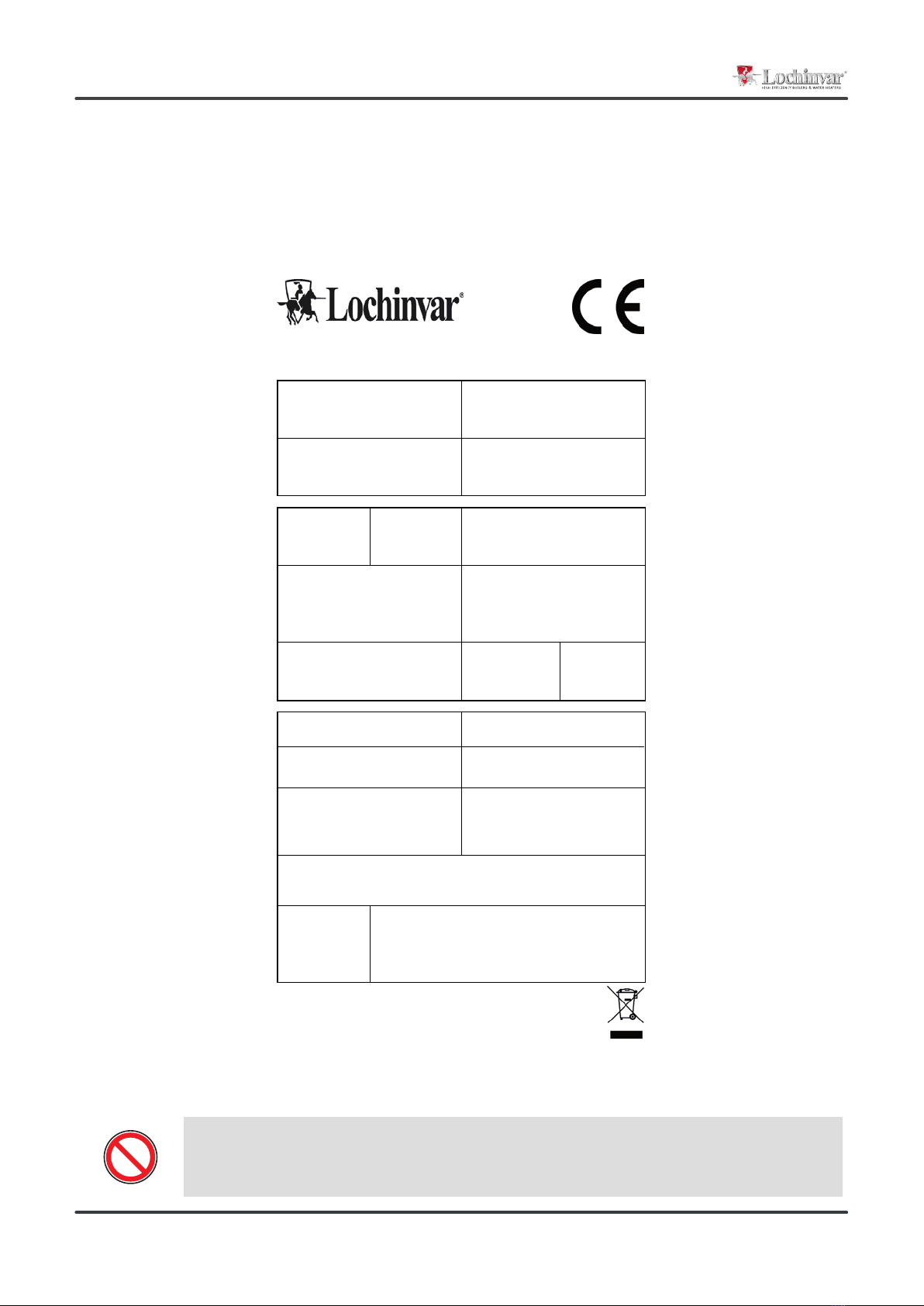
1.10 Unit identication .......................................................................................................................................................... 8
2. SAFETY .............................................................................................................................................................................................. 9
2.1 Warning re potentially hazardous toxic substances ........................................................................................................ 9
2.2 Refrigerant handling ....................................................................................................................................................... 9
2.3 Prevention of inhalation of high vapor concentrations................................................................................................... 10
2.4 Procedures in the event of accidental release of refrigerant ......................................................................................... 10
2.5 Main Toxicological information on the type of refrigerant used...................................................................................... 10
2.6 First aid measures ......................................................................................................................................................... 10
3. TECHNICAL CHARACTERISTICS .................................................................................................................................................... 11
3.1 Unit description.............................................................................................................................................................. 11
3.2 Versions ......................................................................................................................................................................... 12
3.3 Accessories description ................................................................................................................................................. 13
3.4 What is the E.V.I. technology (enhanced vapour injection) ........................................................................................... 14
3.5 Technical data................................................................................................................................................................ 15
3.6 Operation limits.............................................................................................................................................................. 16
3.7 Domestic hot water production ..................................................................................................................................... 17
3.8 Compressor capacity steps ........................................................................................................................................... 18
3.9 Correction tables............................................................................................................................................................ 18
3.10 Sound data .................................................................................................................................................................. 19
4. INSTALLATION................................................................................................................................................................................... 20
4.1 General safety guidelines and and use of symbols ....................................................................................................... 20
4.2 Workers’ health and safety ........................................................................................................................................... 20
4.3 Personal protective equipment ..................................................................................................................................... 20
4.4 Inspection ...................................................................................................................................................................... 21
4.5 Storage .......................................................................................................................................................................... 21
4.6 Unpacking...................................................................................................................................................................... 21
4.7 Lifting and handling........................................................................................................................................................ 22
4.8 Location and minimum technical clearances................................................................................................................. 22
4.9 Installation of rubber vibration dampers (KAVG)........................................................................................................... 24
4.10 Serial interface card RS485 (INSE)............................................................................................................................. 24
4.11 Installation of condensate drip tray (BRCA)................................................................................................................. 25
4.12 Hydraulic connections.................................................................................................................................................. 26
4.13 Chemical characteristics of the water.......................................................................................................................... 26
4.14 Hydraulic components ................................................................................................................................................. 27
4.15 User circuit minimum water content............................................................................................................................. 28
4.16 Domestic hot water (dhw) minimum water content...................................................................................................... 28
4.17 Filling the hydraulic circuit............................................................................................................................................ 28
4.18 Emptying the installation.............................................................................................................................................. 28
4.19 Typical installations ..................................................................................................................................................... 29
4.20 Wiring connections: Preliminary safety information ..................................................................................................... 30
4.21 Electric data................................................................................................................................................................. 31
4.22 Electric connections..................................................................................................................................................... 32
4.23 Positioning of the user circuit water inlet sensor (BTI)................................................................................................. 35
4.24 Refrigerant circuit layout.............................................................................................................................................. 36

Rev. A 11-2020
3
5. UNIT START UP..................................................................................................................................................................................38
5.1 Preliminary Checks........................................................................................................................................................ 38
5.2 Position of the control panel .......................................................................................................................................... 40
5.3 How to remote the control panel.................................................................................................................................... 41
6. USE ............................................................................................................................................................................................. 43
6.1 Switch the unit on .......................................................................................................................................................... 43
6.2 Stop ............................................................................................................................................................................... 44
6.3 How to change the set points ........................................................................................................................................ 45
6.4 PROBES key ................................................................................................................................................................. 46
6.5 ALARM key.................................................................................................................................................................... 46
6.6 CIRC key ....................................................................................................................................................................... 47
6.7 SERVICE key ................................................................................................................................................................ 49
6.8 Acoustic signal silencing ................................................................................................................................................ 60
7. UNIT MAINTENANCE......................................................................................................................................................................... 61
7.1 General warnings........................................................................................................................................................... 61
7.2 Drive access .................................................................................................................................................................. 61
7.3 Scheduled maintenance ................................................................................................................................................ 62
7.4 Periodical checks........................................................................................................................................................... 62
7.5 Refrigerant circuit repair ................................................................................................................................................ 64
8. DECOMMISSIONING......................................................................................................................................................................... 65
8.1 Unit Isolation & drain down............................................................................................................................................ 65
8.2 Disposal, recovery and recycling .................................................................................................................................. 65
8.3 RAEE directive (only for EC countries).......................................................................................................................... 65
9. DIAGNOSIS & TROUBLESHOOTING .............................................................................................................................................. 66
9.1 Fault nding .................................................................................................................................................................. 66
Declaration of conformity
We declare under our own responsibility that the below equipment complies in all parts with the CEE and EN directives.
The declaration of conformity is enclosed to the technical booklet enclosed with the unit. The unit contains uorinated greenhouse gases.

Rev. A 11-2020
4
1. INTRODUCTION
1.1 Preliminary information
1.2 Aim and content of the manual
1.3 How to store this manual
1.4 Manual Update
1.5 How to use this manual
Reproduction, storage or transmission of any part of this publication in any form, without the prior written consent of the Company, is
prohibited.
The unit to which these instructions refer, is designed to be used for the the purposes described and to be operated in accordance with
these instructions.
The Company will not be liable for claims for damage caused to persons, animals, material goods or property caused by improper installa-
tion, adjustment and maintenance or improper use. Any use not specied in this manual is prohibited.
This document is intended to provide information only and does not form a contract with third parties.
The Company pursues a policy of constant improvement and development of its products and therefore reserves the right to change the
specications and the documentation at any time, without notice and without obligation to update existing equipment.
These instructions are intended to provide the information required for the selection, installation, use and maintenance of the unit.
They have been prepared in accordance with the CE/UKCA requirements and with the technical standards in force at the date of issue of
the instructions.
The instructions contain all the necessary information to prevent any reasonably foreseeable misuse.
The manual must be kept in a suitable place with easy access for users and operators, protected from dust and damp.
The manual must always accompany the unit during the entire life cycle of the same and therefore must be transferred to any subsequent
user.
It is recommended that the manual is updated to the latest revision available.
If updates are sent to the customer they must be added to this manual.
The latest information regarding the use of its products is available by contacting the Company.
The manual is an integral part of the unit.
Users or operators must consult the manual before performing any operation and especially so when transporting,
handling, installating, maintaining, or dismantling the unit in order to eliminate uncertainty and reduce risk.
In these instructions symbols have been used (described in the following paragraphs) to draw the attention of operators
and users to the operations that have a higher risk and which must be performed safely.

Rev. A 11-2020
5
1.6 Potential Risks
Whilst the unit has been designed to minimize any risk posed to the safety of people who will interact with it, it has not been technically
possible to eliminate completely the causes of risk. It is therefore necessary to refer to the requirements and symbolism below:
LOCATION OF
RISK
POTENTIAL
RISK METHOD OF INJURY PRECAUTIONS
Thermal heat
exchangers. Small stab wounds. Contact Avoid any contact,
use protective gloves.
Fan and fan grilles. Cuts, eye damage,
broken bones.
Insertion of sharp objects
through the grid while the
fans are operating.
Never put objects through the protection grilles.
Internal component:
compressors and
discharge pipes
Burns. Contact Avoid any contact, use protective gloves.
Internal component:
electric cables and
metallic parts
Electrocution,
severe burns.
Defect in the supply ca-
ble insulation, live metal-
lic parts.
Adequate protection of power cables, ensure
correct earthing of all metal parts.
External to unit:
unit enclosure
Poisoning,
severe burns.
Fire due to short circuit
or overheating of the
supply cable external to
unit.
Size cables and mains protection system in ac-
cordance with iee regulations.
Low pressure safety
valve.
Poisoning,
severe burns.
High evaporating pres-
sure causing a refgrig-
erant discharge during
maintenance.
Carefully check the evaporating pressure dur-
ing the maintenance operations. Use all personal
protective equipment required by the law. PPE
must also protect against gas leaks from the
safety valve. The outlet of these valves is di-
rected to avoid causing damage to persons or
goods.
High pressure safety
valve.
Poisoning,
severe burns,
hearing loss.
Activation of the high
pressure safety valve
with the refrigerant circuit
open.
If possible, do not open the refrigerant circuit
valve; carefuly check the condensing pressure;
use all the personal protective equipment re-
quired by law. PPE must also protect against gas
leaks from the safety valve. The outlet of these
valves is directed to avoid causing damage to
persons or goods.
Entire unit External re
Fire due to natural dis-
asters or combustions of
elements nearby unit
Provide the necessary re-ghting equipment
Entire unit
Explosion, injuries,
burns, poisoning,
folgoramento for natural
disasters or earthquake.
Breakages, failures due
to natural disasters or
earthquake
Plan the necessary precautions both electrical
(suitable differential magneto and electrical pro-
tection of the supply lines; greatest care during the
connections of the metal parts), and mechanical
(special anchors or seismic vibrations to prevent
breakages or accidental falls ).

Rev. A 11-2020
6
BANNED
A black symbol inside a red circle with a red diagonal indicates an action that should not be performed.
WARNING
A black graphic symbol added to a yellow triangle with black edges indicates danger.
ACTION REQUIRED
A white symbol inserted in a blue circle indicates an action that must be done to avoid a risk.
The graphic symbol “warning” is qualied with additional safety information (text or other symbols).
Safety symbols combined in accordance with ISO 3864-2:
1.7 General Description of Symbols Used
Safety symbols combined in accordance with ISO 3864-2:

Rev. A 11-2020
7
GENERAL RISK
Observe all signs placed next to the pictogram. The failure to follow directions may create a risk situation that may
be injurious to the user.
ELECTRICAL HAZARD
Observe all signs placed next to the pictogram.
The symbol indicates components of the unit and actions described in this manual that could create an electrical
hazard.
MOVING PARTS
The symbol indicates those moving parts of the unit that could create risk.
HOT SURFACES
The symbol indicates those components with high surface temperature that could create risks.
SHARP SURFACES
The symbol indicates components or parts that could cause stab wounds.
EARTH CONNECTION
The symbol identies Earthing connection points in the unit.
READ AND UNDERSTAND THE INSTRUCTIONS
Read and understand the instructions of the machine before any operations.
RECOVER OR RECYCLE MATERIAL
1.8 Safety symbols used
The unit is not suitable for operations in environments:
• excessively dusty or potentially explosive atmospheres;
• where there are vibrations;
• where there are electromagnetic elds;
• where there are aggressive atmospheres
The machine is designed and built exclusively for the uses described in “Limitations of use” of the technical manual.
Any other use is prohibited because it may pose a potential risk to the health of operators and users.
1.9 Limitations and prohibited use

Rev. A 11-2020
8
1LZT.0452.HA.XL.HH.2S.00-1B
42,40 A
Manufacturer: FO337725
The MXL Centre, 7 Lombard Way
OX16 4TJ Banbury Oxfordshire
United Kingdom
400V-3ph-50Hz
25/2021
F.L.A. (A)
Voltage-Phases-Frequency
LOW PRESSURE SIDE
Ì244150oÎ
F.L.I. (kW)
Weight
29,5 bar 45 bar
2088
PS
HIGH PRESSURE SIDE
PS
Design temperature
Contains fluorinated greenhouse gasses.
2
-10 °C
30,28 ton
Design temperature
Serial number
Manufacturing datePED Category
Matricola
Data di produzioneCategoria PED
Tipo refrigerante
Refrigerant type GWPFluid group
Gruppo fluido
Min Max Liq
Min Max
LATO ALTA PRESSIONELATO BASSA PRESSIONE
Tensione-Fasi-Frequenza
Peso a vuoto
Temperatura di progetto Temperatura di progetto
CO Equivalent
CO 2
2
EquivalenteCarica refrigerante
Refrigerant charge
Barcode
14,5 kg
C1
C3 C4
C2
27,10 kW
Contiene gas fluorurati ad effetto serra.
50 °C-10 °C
R410A 2
0948
244150
244150
Heat pump
Pompa di calore
Max Gas
125 °C
80 °C
Taratura organo di sicurezza
Safety device calibration
45 bar
The product label should never be removed from the unit.
1.10 Unit identication
Each unit has a rating plate that provides key information regarding the machine.
The rating plate may differ from the one shown below as the example is for a standard unit without accessories.
For all electrical information not provided on the label, refer to the wiring diagram.
A facsimile of the label is shown below:

Rev. A 11-2020
9
For further information regarding the characteristics of the refrigerant and oil used, refer to the safety data sheets
available from the refrigerant and oil manufacturers.
2.1 Warning re potentially hazardous toxic substances
2.1.2 Identication of the Type of Oil Used.
2. SAFETY
The lubricant used is polyester oil. Please refer to the information provided on the compressor data plate.
ENVIRONMENTAL PROTECTION : Read the ecological information and the following instructions carefully.
2.1.3 Persistence and degradation
2.1.4 Effects of discharges
2.1.5 Exposure controls and personal protection
2.1.6 Professional exposure limits
2.2 Refrigerant handling
The refrigerants used decompose in the lower atmosphere (troposphere) relatively quickly. The decomposed products are highly dispersible
and therefore have a very low concentration. They do not inuence the photochemical smog which is not among the VOC volatile organic
compounds (as stipulated in the guidelines to the UNECE). The constituent refrigerants of R410A, do not damage the ozone layer. These
substances are regulated under the Montreal Protocol (revised 1992) and regulations EC no. 2037/200 of 29 June 2000.
Discharges into the atmosphere of this product does not cause a long-term contamination.
Wear protective clothing and gloves, protect your eyes and face
R410A
HFC-32 TWA 1000 ppm
HFC-125 TWA 1000 ppm
Main Ecological Information Regarding the Types of refrigerants Fluids used.
Users and maintenance personnel must be F-Gas registered and competent. Failure to follow such instructions can
cause damage to personnel or to the unit.
2.1.1 Identication of the Type of Refrigerant Fluid Used: R410A
• Diuoromethane (HFC-32) 50% by weight CAS No.: 000075-10-5
• Pentauoroethane (HFC-125) 50% by weight CAS No.: 000354-33-6

Rev. A 11-2020
10
2.3 Prevent inhalation of high vapor concentration
2.4 Procedures to be adopted in the event of accidental release of refrigerant
2.5 Main Toxicological Information Regarding the Type of refrigerant used
2.5.1 Inhalation
A high atmospheric concentration can cause anaesthetic effects with possible loss of consciousness. Prolonged exposure may lead to irre-
gular heartbeat and cause sudden death. Higher concentrations may cause asphyxia due to the reduced oxygen content in the atmosphere.
2.5.2 Contact with skin
Splashes of nebulous liquid can produce frostbite. Probably not hazardous if absorbed trough the skin. Repeated or prolonged contact may
remove the skin’s natural oils, with consequent dryness, cracking and dermatitis.
2.5.3 Contact with eyes
Splashes of liquid may cause frostbite.
2.5.4 Ingestion
While highly improbable, may produce frostbite.
Atmospheric concentrations of refrigerant must be minimized and kept to a level that is below the occupational exposure limit. Vapor is
heavier than air and can form dangerous concentrations near the ground where the ventilation rate is lower. Always ensure adequate venti-
lation. Avoid contact with open ames and hot surfaces as this can cause toxic and irritating decomposition products to form. Avoid contact
between liquid refrigerant and the eyes or skin.
Ensure suitable personal protection (especially respiratory protection) during cleaning operations.
If deemed safe, isolate the source of the leak. If the leakage is small and if adequate ventilation is provided, allow the refrigerant to evapo-
rate. If the loss is substantial ensure that measures are taken to adequately ventilate the area.
Contain spilled material with sand, earth or other suitable absorbent material.
Do not allow the refrigerant to enter drains, sewers or basements, as pockets of vapor can form.
2.6 First Aid Measures
2.6.1 Inhalation
2.6.2 Contact with skin
Move the person away from the source of exposure, keep him/her warm and let him/her rest. Seek medical assistance.
In case of contact with skin, wash immediately with lukewarm water. Thaw tissue using water. Remove contaminated clothing. Clothing may
stick to the skin in case of frostbite. If irritation, swelling or blisters appear, seek medical assistance.
Adhere scrupulously to the warnings and rst aid procedures indicated below.
2.6.3 Contact with eyes
Rinse immediately using an eyewash or clean water, keeping eyelids open, for at least ten minutes. Seek medical assistance.
2.6.4 Ingestion
Do not induce vomiting. If the injured person is conscious, rinse his/her mouth with water and make him/her drink 200-300ml of water. Seek
immediate medical assistance.
2.6.5 Further medical treatment
Treat symptoms and carry out support therapy as indicated. Do not administer adrenaline or similar sympathomimetic drugs following
exposure, due to the risk of cardiac arrhythmia.

Rev. A 11-2020
11
3. TECHNICAL CHARACTERISTICS
3.1 Unit description
The LZT series of high efciency heat pumps has been specically designed for use with radiant oor heating systems or those applications
where it is necessary to have maximum efciency when heating.
They have been optimized on heating mode, are able to produce water up to 65°C and can operate down to -20°C ambient temperature.
All versions are supplied with reverse cycle valve used for winter defrost; the HH version is suitable for use in those countries that have
support schemes for use of heat pump technology for heating. The RV versions are also able to produce cold water. The HH heating only
versions is factory set and locked to operate only in heating mode whilst. The noise in XL and NN versions is extremely low thanks to the
use of a special oating vibration damping system which allows a noise reduction of about 10-12 dB(A).
3.1.1 Frame
All units are made from hot-galvanised sheet steel, painted with polyurethane powder enamel and stoved at 180°C to provide maximum
protection against corrosion. The frame is self-supporting with removable panels. All screws and rivets used are made from stainless steel.
The standard colour of the units is RAL9018.
3.1.2 Refrigerant circuit
The refrigerant utilised is R410A. The refrigerant circuit is assembled using internationally recognised brand name components with all
brazing and welding being performed in accordance with ISO 97/23. The refrigerant circuit includes: sight glass, lter drier, two thermal
expansion valves (one for cooling mode, one for heating mode) with external equalizer, 4 way reversing valve, check valves, liquid receiver,
Schrader valves for maintenance and control, pressure safety device (for compliance with PED regulations). The circuit also includes an
AISI316 stainless steel heat exchanger that is used as an economizer plus an additional expansion valve for refrigerant vapour injection.
3.1.3 Compressors
Units use scroll compressors that are equipped with E.V.I. technology, a versatile method of improving system capacity and efciency. EVI
stands for “Enhanced Vapour Injection.” The technology involves injecting refrigerant vapour into the middle of the compression process, a
procedure that signicantly boosts capacity and efciency. Each scroll compressor used in these units is similar to a two-stage compressor
with built-in inter-stage cooling. The process begins when a portion of the condenser liquid is extracted and expanded through an expan-
sion valve. The low temperature liquid/gas mixture produced is injected into a heat exchanger that operates as a sub cooler. Any liquid is
evaporated and the vapour produced is superheated. The superheated vapour is then injected into an intermediate port in the scroll com-
pressor. This cold vapour reduces the temperature of the compressed gas thus enabling the compressor to raise the pressure to levels (and
temperatures) beyond that possible with a single stage scroll. The additional sub cooling of the main volume of liquid refrigerant increases
the evaporator capacity. This compressor technology generates a larger pressure ratio between condensing and evaporating pressures,
with signicant performance improvement. In all units the compressors are connected in tandem. The compressors are all supplied with a
crankcase heater and thermal overload protection by a klixon embedded in the motor winding. They are mounted in a separate enclosure
in order to be separated from the air stream thus enabling them to be maintained even if the unit is operating. Access to this enclosure is
by the front panel of the unit. The crankcase heater is always powered when the compressor is in stand-by.
3.1.4 Source heat exchanger
The source heat exchanger is made from 3/8” copper pipes and 0,1mm thick aluminium ns with the tubes being mechanically expanded
into the aluminium ns in order to maximise heat transfer. Furthermore, the design guarantees a low air side pressure drop thus enabling
the use of low rotation speed (and hence low noise) fans. All heat exchangers are supplied standard with ns hydrophilic coating.
3.1.5 Fans
The fans are direct drive axial type with aluminium aerofoil blades, are statically and dynamically balanced and are supplied complete with
a safety fan guard complying with the requirements of EN 60335. They are xed to the unit frame via rubber antivibration mountings.In the
LS versions the fans are 6 poles type (approx 900 rpm), in the XL versions the fans are 8 poles type (approx 600 rpm), in the NN versions
the fans are 12 poles type (approx 450 rpm). The motors are tted with integrated thermal overload protection and have a moisture protec-
tion rating of IP 54.
3.1.6 User heat exchangers
The user heat exchanger is a braze welded, plate type heat exchanger, manufactured from AISI 316 stainless steel. The use of this type of
exchanger results in a massive reduction of the refrigerant charge of the unit compared to a traditional shell-in-tube type. A further advan-
tage is a reduction in the overall dimensions of the unit. The exchangers are factory insulated with exible close cell material and can be
tted with an antifreeze heater (accessory). Each exchanger is tted with a temperature sensor on the discharge water side for antifreeze
protection.

Rev. A 11-2020
12
3.1.7 Electric enclosure
The enclosure is manufactured in order to comply with the requirements of the electromagnetic compatibility standards CEE EN60204.
Access to the enclosure is achieved by removing the front panel of the unit. The following components are supplied as standard on all
units: main switch, a sequence relay that disables the power supply in the event that the phase sequence is incorrect (scroll compressors
can be damaged if they rotate in the wrong direction), thermal overloads (protection of pumps and fans), overload switches, control circuit
automatic breakers, compressor contactors, automatic switches and pump contactors. The terminal board has volt free contacts for remote
ON-OFF, Summer/ winter change over (heat pumps only) and general alarm.
3.1.8 Microprocessors
All units are supplied as standard with microprocessor controls. The microprocessor controls the following functions: control of the water
temperature, antifreeze protection, compressor timing, compressor automatic starting sequence (For multiple compressors), alarm reset.
The control panel is supplied with display showing all operational icons. The microprocessor is set for automatic defrost (when operating in
severe ambient conditions) and for summer/ winter change over.
The control also manages the anti-legionella program, the integration with other heating sources (electric heaters, boilers, solar panels
etc), the operation of a three port modulating valve (for diverting to DHW or heating) and both the heating circuit pump and the domestic
hot water circuit pump. If required (available as an option), the microprocessor can be congured in order for it to connect to a site BMS
system thus enabling remote control and management. The Lochinvar technical department can discuss and evaluate, in conjunction with
the customer, solutions using MODBUS protocols.
3.1.9 Control and protection devices
All units are supplied with the following controls and protections: user water return temperature sensor, antifreeze protection temperature
sensor installed on users water output, domestic hot water supply and return temperature sensors (only versions P2S), high pressure
manual reset, low pressure automatic reset, compressor thermal protection, air fan, thermal protection, pressure transducer (used to opti-
mize the defrost cycle and to adjust the fan speed depending on ambient conditions), ow switch. All units are also tted with a temperature
probe sensor with “Energy Saving” function, supplied in a separate plastic box, which can be used to stop the pump use during periods of
stand-by, when the water temperature reaches the set point. Doing this the power consumption of the unit is strongly reduced. The probe
sensor must be positioned in the hydraulic compensator present at the screening technique. The domestic hot water circuit (only versions
P2S) is already equipped with this probe, but it must be installed in the user circuit.
3.1.10 User ow switch
The ow utility is installed as standard on all units and disables the operation of the unit in case of abnormal water ow in the system. The
ow switch is made of a blade system tted in the ow of the water; it is combined with two permanent magnets that assess the amount of
water in transit and, in function of the measured parameter, enable or not the operation of the unit.
3.2 Versions
3.2.1 Version HH
HH heating only versions are available in the P2U and P2S conguration only.
3.2.6 HE Version
High efciency version, according to ERP2018 standard. Unit equipped with EC fans.
3.2.8 Version XL
All versions are supplied, as standard, with the latest ‘Floating Frame’ technology that completely isolates the compressors from the main
casing, thereby eliminating vibration and noise from this source. The ‘Floating Frame’ is a special vibration and acoustic damping system
that consists of a base plate and acoustic enclosure that houses the compressors. The base plate is separated from the supporting frame
of the unit by soft steel springs that have a high damping power. Within the enclosure, the compressors are mounted on rubber shock ab-
sorbers on the oating base plate. The enclosure is manufactured from galvanized steel sandwich panels that have a core of 30 mm thick,
high density (25 kg/m3) mineral wool. The entire arrangement provides a double damping system and acoustic attenuation. The compressor
refrigerant pipes are connected to the refrigerant circuit through “anaconda” exible connections. Flexible connections are also used on the
water pipework within the unit. The combination of these systems results in an overall noise reduction in the region of 10-12 dB(A).
3.2.10 Version P2U
This is a two pipe version that can produce hot water for heating and cold water for cooling. The unit is used with two pipe water based
change-over systems. It is not able to produce domestic hot water.
3.2.11 Version P2S
This is a two pipe version that can, in addition to producing hot water for heating and cold water for cooling, also generate domestic hot

Rev. A 11-2020
13
water. The controller has dual heating set points (heating and DHW) and can also control a three port diverting valve that directs the DHW
to the cylinder. DHW production has priority irrespective of the mode of operation of the unit. The unit is normally used with two pipe water
based change-over systems.
3.3 Accessories description
3.3.1 Condensate discharge drip tray with antifreeze heater (BRCA)
Installed under the nned heat exchanger, this is used to collect the condensate generated during the heating mode operation. It is tted
with trace heating to prevent ice formation in low ambient conditions. This accessory may only be factory tted.
3.3.2 Antifreeze kit (RAEV2, RAEV4)
This kit, used on units tted with a hydraulic kit, comprises a “self-heating” electric cable that is wrapped around the user and domestic hot
water exchanger (P4 Units only), the water circuit pipework. This device is controlled by the microprocessor.
3.3.3 Rubber vibration dampers (KAVG)
To be installed beneath the unit base and the ground to avoid the transmission of vibrations (and the noise) to the building.
3.3.4 RS485 serial interface card modbus protocol (INSE)
This controller card enables the controller to communicate with other devices on a BMS using Modbus protocol.
3.3.6 Electronic expansion valve (VTEE)
The electronic expansion valve enables the maximum possible efciency to be achieved by maximising the evaporator heat exchange,
minimising the reaction time to load variations and optimising the superheat . It is strongly recommended for use in systems that will experi-
ence large load variations.
3.3.7 Electronic soft starter (DSSE)
All units are supplied, standard with the soft starter device who minimize the peak starting current of the compressor reducing down to the
same value of the nominal maximum input current.
3.3.8 Remote control panel (PCRL)
All units are supplied with microprocessor control panel with high denition display, mounted on board of the unit and it is remotable up to
50 mt. distance.
3.3.9 Hydraulic circuit antifreeze kit (KP)
This kit, used on units tted with a hydraulic kit, comprises a “self-heating” electric cable that is wrapped around the user and domestic hot
water exchanger (P4 Units only), the water circuit pipework and includes an armoured electric heater that is tted inside the water tank. This
device is controlled by the microprocessor and it is used in the unit equipped with hydraulic kit.
3.3.10 Hydraulic kit with one pump without tank - user circuit (A1NTU)
It includes: 1 water pump, expansion vessel, pressure relief valve (if required by PED norms).
3.3.12 Cascade control system (SGRS)
Cascade control system for the managment of units. The system is made of a separate plastic box, to be installed in the technical room.
It is connected to the units via RS485.

Rev. A 11-2020
14
2,0
2,5
3,0
3,5
4,0
-15 -10 -5 0 5 10 15
10
-20 -10 0 10 20 30 40 50
20
30
40
50
60
70
2,0
2,5
3,0
3,5
4,0
-15 -10 -5 0 5 10 15
10
-20 -10 0 10 20 30 40 50
20
30
40
50
60
70
Pi
P
Pm+i
Pm
Ph
Pi
HX
TEV
m +i
m
i
TEV
C.O.P.
The above graph shows the operation range of the EVI scroll compressors supplied in the units; at -20°C ambient the water outlet tempe-
rature is still 52°C; this performance makes the installation of a heat pump suitable for any European condition.
Ambient temperature (°C)
Max Water
Temperature (°C)
The efciency of EVI compressors at low ambient conditions is about 25% higher than standard scroll compressors. The effect of this
difference becomes even more evident in applications that require high hot water temperatures (i.e. when domestic hot water is required).
In such applications the operational limits of a standard scroll compressor prevent it from producing the required hot water temperature at
air ambient temperatures below 5°C.
The graph below shown the trend of the coefcient of performance C.O.P. compared with a standard scroll compressor (dotted line); EVI
scroll compressor (Continuous curve).
Water production at 40°C
Water production at 55°C
Water production at 40°C
Water production at 55°C
Ambient temperature (°C)
EVI stands for “Economised Vapour Injection.” The technology involves injecting refrigerant vapour into the middle of the compression process,
a procedure that signicantly boosts capacity and efciency. Each scroll compressor used in these units is similar to a two-stage compressor
with built-in inter-stage cooling. The process begins when a portion of the condenser liquid is extracted and expanded through an expansion
valve. The low temperature liquid/gas mixture produced is injected into a heat exchanger that operates as a sub cooler. Any liquid is evaporated
and the vapour produced is superheated. The superheated vapour is then injected into an intermediate port in the scroll compressor. This
cold vapour reduces the temperature of the compressed gas thus enabling the compressor to raise the pressure to levels (and temperatures)
beyond that possible with a single stage scroll. The additional sub cooling of the main volume of liquid refrigerant increases the evaporator
capacity. This compressor technology generates a larger pressure ratio between condensing and evaporating pressures, with signicant
performance improvement. Using this technology enables the units to produce hot water up to 65°C and the ability to operate down to -20°C
ambient temperature.
3.4 What is the E.V.I. technology (enhanced vapour injection)

Rev. A 11-2020
15
Heating only version (HH)
The refrigerant data may change without notice. It is therefore necessary to refer always to the silver label placed
on the unit.
Model LAHP-
252HT
LAHP-
LAHP-
432HT
LAHP-
492HT
LAHP-
LAHP-
752HT
LAHP-
852HT
LAHP-
LAHP-
Heang capacity (EN14511)1kW 24 30 41.2 49.2 57.4 65.6 79.9 87.2 100.7
Total power input (EN14511)1kW 5.2 6.8 9.2 11.8 12.9 15.1 17.8 19.4 23.5
COP (EN14511)1W/W 4.64 4.39 4.49 4.16 4.57 4.35 4.49 4.49 4.29
Energy label rang low temperature A++ A++ A++ A++ A++ A++ A++ A++ A++
SCOP low temperature 4.1 3.87 4 3.84 4.21 4.16 4.04 4.06 3.93
Seasonal eciency low temperature %161 151.8 157.1 150.6 165.4 163.4 158.7 159.5 154
Energy label rang high temperature A++ A+ A++ A++ A++ A++ A++ A++ A++
SCOP high temperature 3.24 3.14 3.24 3.16 3.38 3.29 3.26 3.33 3.25
Seasonal eciency high temperature %126.5 122.7 126.6 123.4 132 128.6 127.3 130 126.9
Refrigerant R410A R410A R410A R410A R410A R410A R410A R410A R410A
Power supply V/Ph/Hz 400/3+N/50
Maximum input current standard unit A20.6 24 34.2 39.4 44.2 54.2 67.6 68.6 77.4
Peak input current standard unit A62.9 83.1 119 149 141 168 209 210 208
Fans No222222222
Compressors/refrigerant circuits No2/1 2/1 2/1 2/1 2/1 2/1 2/1 2/1 2/1
Sound power level2dB(A) 70 72 73 74 73 73 74 75 75
Sound pressure level3dB(A) 38 40 41 42 41 41 42 43 43
1) External air+7C 30/35 ow
2) Average condions according to EU/811/2013
3) Sound power level in accordance with ISO3744
3.5 Technical data

Rev. A 11-2020
16
20
30
40
50
60
70
-30 -20 -10 0 10 20 30 40 50
1
2
21
3.6 Operation limits
3.6.1 User heat exchanger water ow rate
The nominal water ow rate given is referred to a ∆t of 5 °C. Maximum ow rate allowed is the one that presents a ∆t of 3°C: higher values
may cause too high pressure drop.
The minimum water ow rate allowed is the one presenting a ∆t of 8°C.
Insufcient values cause too low evaporating temperatures with the action of safety devices which would stop the unit.
3.6.2 User hot water temperature (Winter operation)
Once the system is on temperature, the minimum user water temperature should not be less than 30°C.
Lower values could cause incorrect working operation of the compressor and compressor failure may occur.
The maximum user outlet water temperature cannot exceed 65°C; higher values may call the action of safety devices which would stop
the unit.
3.6.4 Ambient air temperature
The units are designed and manufactured to operate, In winter operation (heating mode ) from -20°C to 43°C.
In cooling mode the units can operate with ambient air temperatures from -10 to 43°C.
Heating mode
Ambient temperature (°C)
Water temp. production (°C)
(HA/HE versions)
Heating mode with head pressure control (DCCF)

Rev. A 11-2020
17
All units are supplied as standard with evaporating/condensing pressure control. This feature allows the unit to
operate in heating mode above 15°C and in cooling mode below 20°C ambient temperature. The device monitors
the evaporating/condensing pressure and maintains it at a constant level by modulating the airow. It can also be
used to reduce noise emission when ambient temperatures are lower (eg. at night).
Units are designed and manufactured to European safety and technical standards. The units have been designed
exclusively for heating, cooling and domestic hot water production (D.H.W.). The units must be used for this specic
purpose only. The Company will not be liable for claims for damage caused to persons, animals or material goods
or property caused by improper installation, adjustment and maintenance or improper use. Any use not specied in
this manual is prohibited.
In case of operations outside of these values, please contact the company.
In WINTER mode, the unit can be started with external air of -20°C and cold inlet water (about 20°C). Such a
conguration is allowed only for a short time and only to bring the plant to the right temperature.
To reduce this setting time, we suggest to install a 3-way valve which allows to by-pass water from the user to the
plant till the standard conditions are reached.
If the unit is installed in particularly windy areas, it will be necessary to provide some windbreaker barriers to avoid
any malfunction. We suggest to install the barriers only if the wind exceeds 2,5m/s.
The units, in their standard conguration, are not suitable for installation in saline environments.
3.7 Domestic hot water production
The production of domestic hot water through heat pump is a sensitive issue that deserves proper consideration. There are several systems
of domestic hot water production by using heat pumps, each of which brings advantages and disadvantages. It is not subject of this manual
to deal with the matter in depth and in the case, please contact the company for all the appropriate solutions.

Rev. A 11-2020
18
10 -3.2 0.985 1 1.02 1.08
20 -7.8 0.98 0.99 1.05 1.12
30 -14.1 0.97 0.98 1.09 1.22
40 -22.3 0.965 0.97 1.14 1.25
50 -33.8 0.955 0.965 1.2 1.33
358
CCCP 0.99 1 1.02
IPCF 0.99 1 1.01
0.00005 0.0001 0.0002
CCCP 1 0.98 0.94
IPCF 1 0.98 0.95
1 2
252 50% 50%
312 50% 50%
432 50% 50%
492 50% 50%
592 50% 50%
752 50% 50%
852 50% 50%
1002 50% 50%
1202 50% 50%
Glycol percentage Freezing point (°C) CCF IPCF WFCF PDCF
Water temperature diff.(°C)
CCCP = Cooling capacity correction factor IPCF = Input power correction factor
Fouling factor
CCCP = Cooling capacity correction factor IPCF = Input power correction factor
3.9.1 Operation with glycol
3.9 Correction tables
3.9.2 Correction tables different ∆t
3.9.3 Correction tables different Fouling factors
CCF: Capacity correction factor IPCF: Input power correction factor
WFCF: Water ow correction factor PDCF: Pressure drops correction factor
The water ow rate and pressure drop correction factors are to be applied directly to the values given for operation without glycol. The water
ow rate correction factor is calculated in order to maintain the same temperature difference as that which would be obtained without glycol.
The pressure drop correction factor takes into account the different ow rate obtained from the application of the ow rate correction factor.
NUMBER of COMPRESSORS
Model
3.8 Compressor capacity steps

Rev. A 11-2020
19
HA / XL
Mod.
Lw Lp
63 125 250 500 1K 2K 4K 8K dB dB(A) dB(A)
dB dB dB dB dB dB dB dB
252/HA/XL 85,1 76,3 70,2 68,7 67,6 62,2 58,8 49,7 85,9 72 40
312/HA/XL 85,1 76,3 70,2 68,7 67,6 62,2 58,8 49,7 85,9 72 40
432/HA/XL 86,1 77,3 71,2 69,7 68,6 63,2 59,8 50,7 86,9 73 41
492/HA/XL 87,1 78,3 72,2 70,7 69,6 64,2 60,8 51,7 87,9 74 42
592/HA/XL 87,1 78,3 72,2 70,7 69,6 64,2 60,8 51,7 87,9 74 42
752/HA/XL 87,1 78,3 72,2 70,7 69,6 64,2 60,8 51,7 87,9 74 42
852/HA/XL 87,1 78,3 72,2 70,7 69,6 64,2 60,8 51,7 87,9 74 42
1002/HA/XL 88,1 79,3 73,2 71,7 70,6 65,2 61,8 52,7 88,9 75 43
1202/HA/XL 88,1 79,3 73,2 71,7 70,6 65,2 61,8 52,7 88,9 75 43
3.10 Sound data
Lw: Sound power level according to ISO 3744.
Lp: Sound pressure level measured at 10 mt from the unit in free eld conditions direction factor Q=2 according to ISO 3744.
Octave bands (Hz)

Rev. A 11-2020
20
When operating and maintaining the unit, use the following personal protective equipment listed below as required
by law.
Protective footwear.
Eye protection.
Protective gloves.
Respiratory protection.
Hearing protection.
4.3 Personal protective equipment
4.2 Health and safety Considerations
The workplace must be kept clean, tidy and free from objects that may prevent free movement. Appropriate ligh-
ting of the work place shall be provided to allow the operator to perform the required operations safely. Poor or too
strong lighting can cause risks.
Ensure that work places are always adequately ventilated and that respirators are working, in good condition and
comply fully with the requirements of the current regulations.
Before undertaking any task the operator must be fully trained in the operation of the machines to be used and
their controls. They must also have read and be fully conversant with all operating instructions.
4. INSTALLATION
4.1 General safety guidelines and and use of symbols
All maintenance must be performed by TRAINED personnel and be in accordance with all national and local regu-
lations.
The installation and maintenance of the unit must comply with the local regulations in force at the time of the installation.
Avoid contact and do not insert any objects into moving parts.
This manual suits for next models
11
Table of contents
Other Lochinvar Heat Pump manuals