Lock Inspection Systems MET 30+ User manual

INSPECTION SYSTEMS
M
ME
ET
T
3
30
0+
+
Metal Detectors
Operating Manual

MET 30+
Operating Manual
(Q875-0143/ENG Issue 2)
Models Covered
Met30+ VFD & Touch Screen
Software Version 4.xx
Su
pp
lied B
y
:
©2010 LOCK Inspection Systems Ltd
Lock House
Neville Street, Oldham
Lancs, OL9 6LF
Tel 0161 624 0333 Fax 0161 624 5181

Doc. Ref.No: Q875-0143/ENG Issue 2 Met 30+ Operating Manual 12/01/10
Copyright ©Lock Inspection Systems Limited. 2010.
This document may not be copied, reproduced, duplicated or translated in any form,
electronic or otherwise without prior official written consent from Lock Inspection
Systems Ltd.
Lock Inspection Systems Limited will not be liable for any incidental or consequential
damage in connection with the use of this document.
Lock Inspection Systems Limited reserves the right to change the contents of this
document at any time without prior notice having been given.
Amendments
Lock Inspection Systems seek to update manuals to include new features and
improvements whenever possible. The revision history is intended to highlight
advances from previous issues of this document.
Revision History
Issue Date Reason For Issue
1 2nd January 2007 Initial release.
2 12th January 2010 Page 29 Section 5.5.7 amended.
File Name: Q875-0143 ENG Iss2 Met30+ Operating.doc Page 1 of 58

Doc. Ref.No: Q875-0143/ENG Issue 2 Met 30+ Operating Manual 12/01/10
CONTENTS
1. GENERAL 5
2. HEALTH AND SAFETY 5
2.1 Health and Safety at Work etc. Act 5
3. INTRODUCTION 6
3.1 Detection Sensitivity 6
3.2 Detection Envelope 7
3.3 Orientation Effects 8
3.4 Sensitivity Gradient 9
3.5 Product Effect 9
3.6 Scope Of This Manual 9
4. SETTING UP THE MACHINE 11
4.1 Detector Display and Keypad 11
4.2 Initial Test 12
4.3 Product Setup 12
4.4 Timer Setup 14
5. USING THE SOFTWARE 17
5.1 Power up 17
5.2 Security Codes 19
5.3 Operator Menu 20
5.4 Supervisor Menu 21
5.5 Engineers Menu 25
File Name: Q875-0143 ENG Iss2 Met30+ Operating.doc Page 2 of 58

Doc. Ref.No: Q875-0143/ENG Issue 2 Met 30+ Operating Manual 12/01/10
6. OPERATION CHART 30
6.1 Met30 + 1fSystem Menu 30
6.2 Met30 + 3fSystem Menu 31
7. SAMPLE TEST 32
7.1 Operation 32
7.2 Recommended action on failing test 33
7.3 Engineering setup 33
7.4 Sample test flowchart 35
8. PRINTER 36
8.1 Print Modes 37
8.2 Reports 40
8.3 Engineering Setup 43
8.4 Printer Cable Diagrams 44
9. TOUCH SCREEN DISPLAYS 45
9.1 ADC Screen 46
9.2 Reports Display 51
9.3 Met30 + 1fSystem Menu (Touch Screen) 54
9.4 Met30 + 3fSystem Menu (Touch Screen) 55
10. TROUBLESHOOTING GUIDE 56
10.1 False Triggering/Poor Sensitivity 56
10.2 Fails to detect test sample 56
10.3 Detects sample but false triggers 56
File Name: Q875-0143 ENG Iss2 Met30+ Operating.doc Page 3 of 58

Doc. Ref.No: Q875-0143/ENG Issue 2 Met 30+ Operating Manual 12/01/10
11. GLOSSARY 57
11.1 Aperture 57
11.2 Bargraph 57
11.3 Test Setup 57
11.4 False Triggering 57
11.5 Metal-Free Zone 57
11.6 Noise 57
11.7 Noise Test 57
11.8 Product Effect 57
11.9 Sensitivity 58
11.10 Systemchek 58
11.11 Test Sample 58
11.12 Trigger 58
11.13 VFD – Vacuum Fluorescent Display 58
11.14 ELD – Electroluminescent Display 58
File Name: Q875-0143 ENG Iss2 Met30+ Operating.doc Page 4 of 58

Doc. Ref.No: Q875-0143/ENG Issue 2 Met 30+ Operating Manual 12/01/10
1. GENERAL
The instructions given in this manual have been written clearly and briefly to enable
an easy understanding of the actions necessary to operate this equipment.
In order to ensure trouble-free and reliable service it is strongly recommended that
operators of the equipment are provided with this manual in order to familiarise
themselves with the controls and procedures.
2. HEALTH AND SAFETY
2.1 Health and Safety at Work etc. Act
The Purchaser shall comply with the instructions and information of this manual, and
it is strongly advised that all personnel associated with this equipment be made
familiar with the information contained herein.
It is essential that the personnel engaged on the operation of the plant be competent
and experienced in the work, and that they comply with the statutory requirements
and regulations, including the provisions of the Health and Safety at Work Act, and
any amendments that may become legal requirements.
Note: For installation of the MET 30+, 1f, 3frange of metal detectors refer to the
Installation Manual.
File Name: Q875-0143 ENG Iss2 Met30+ Operating.doc Page 5 of 58

Doc. Ref.No: Q875-0143/ENG Issue 2 Met 30+ Operating Manual 12/01/10
3. INTRODUCTION
This is the operating manual for the MET 30+ 1f and 3f range of metal detectors
including horizontal, pharmaceutical, waferthin, vertical-fall and pipeline, with VFD or
Touch Screen displays.
The MET 30+ detector uses the latest developments in digital signal processing
ensuring complete product integrity. The detector is able to store up to 100 sets of
automatic product set up values in memory.
The MET 30+ detector is capable of detecting and rejecting ferrous, non-ferrous and
non-magnetic stainless steel.
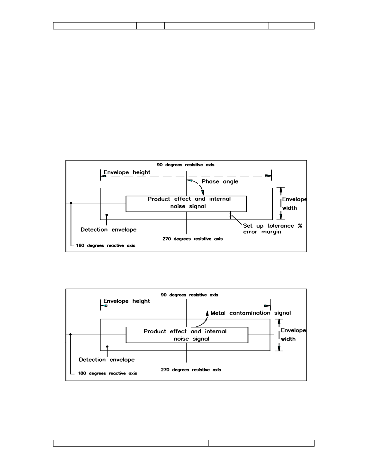
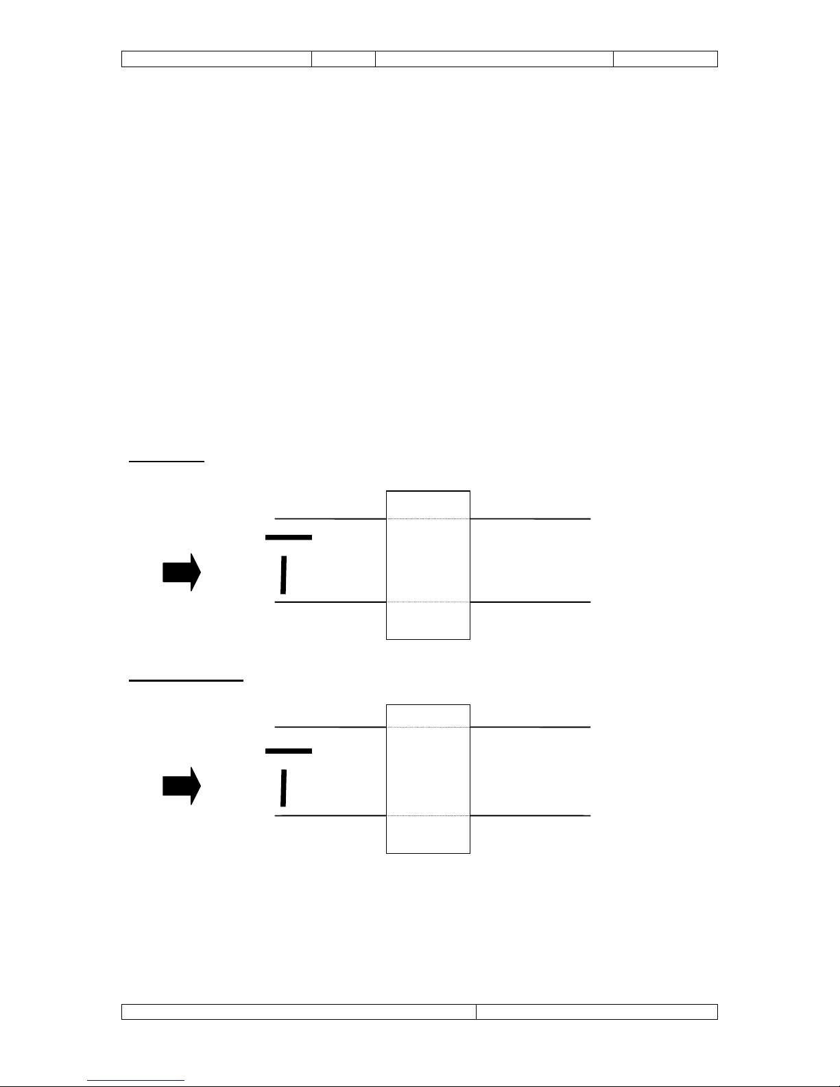
A penetrating electromagnetic field is generated within the detector head, and any
metallic contaminant within the detector specification will distort the electromagnetic
field and be detected no matter how deeply embedded in the product.
On detection a reject relay is activated, this relay is used to switch the automatic
reject device, which rejects the contaminated product.
3.1 Detection Sensitivity
The sensitivity of a metal detector is governed mainly by the size of the aperture
through which the product is passed and is particularly dependent upon the minimum
dimension of that aperture. Therefore, in order to obtain a high sensitivity on a given
product, the aperture size should be kept as small as convenient while allowing
sufficient clearance around the product to prevent blockages.
To overcome discrepancies due to the shape of a metal sample, sensitivities are
always quoted in terms of diameters of spherical samples. This is referred to as
‘Spherical Sensitivity’.
File Name: Q875-0143 ENG Iss2 Met30+ Operating.doc Page 6 of 58

Doc. Ref.No: Q875-0143/ENG Issue 2 Met 30+ Operating Manual 12/01/10
3.2 Detection Envelope
The MET 30+ detector software creates a detection envelope after an automatic
setup is performed, it uses this envelope as a means of detecting metallic
contaminants. For a signal from a metallic contaminant to operate the detection relay
it must produce a vector signal large enough to pass through the periphery of the
detection envelope. (See fig 1a and 1b).
You can alter the sensitivity of the detector by increasing or decreasing the
dimensions of the envelope, known as the width and height. Increasing the envelope
size decreases the sensitivity and decreasing the envelope size increases the
sensitivity. It is found that in the majority of cases altering the width of the envelope
is all that is required to increase or decrease the sensitivity.
Fig 1a Metal detection envelope.
Fig 1b Metal detection envelope with a metal contamination signal shown
breaking out of the detection envelope.
File Name: Q875-0143 ENG Iss2 Met30+ Operating.doc Page 7 of 58

Doc. Ref.No: Q875-0143/ENG Issue 2 Met 30+ Operating Manual 12/01/10
3.3 Orientation Effects
If a wire sample of a particular metal is passed through the aperture, it will be readily
detected if the diameter of the wire is equal to or greater than the ‘spherical
sensitivity’ of the metal detector to the same metal.
When the diameter of the wire becomes less than the ‘spherical sensitivity’ the
orientation effects will be noticed. The wire will be detected more easily with its long
axis presented one way into the aperture than it will be when presented in another
(See figure 1c).
Figure 1c shows that when a piece of non-ferrous or stainless steel wire points in the
direction of travel, it is in the most difficult position to detect, and when pointing 90°
to the direction of travel, it is in the least difficult position. For ferrous wires, the
situation is reversed.
FERROUS
Difficult
Easy Metal
Detecto
r
NON FERROUS
Easy
Difficult Metal
Detecto
r
FIG 1c Orientation Effect
File Name: Q875-0143 ENG Iss2 Met30+ Operating.doc Page 8 of 58

Doc. Ref.No: Q875-0143/ENG Issue 2 Met 30+ Operating Manual 12/01/10
3.4 Sensitivity Gradient
Sensitivity is higher around the peripheries of the aperture and somewhat lower
through the central axis of the aperture. Quoted sensitivities are always given for the
least sensitive area of the aperture, that being along the central axis of the aperture.
3.5 Product Effect
Some products can produce electrical signals when passed through the metal
detector aperture thus making it appear as though there is contamination present.
This is because the product is electrically conductive due to various factors such as
moisture, salt, metallic oxide content, packaging etc.
If there is product effect seen during the automatic setup of a product, the detector
will automatically set an envelope around the product effect signal. This will ensure
that the product effect signals are ignored during production thus preventing false
detection.
If a product has any effect then the resulting detection envelope will be bigger, this
bigger envelope will therefore result in a decrease in sensitivity of the detector.
3.6 Scope Of This Manual
Below is a summary of the information contained in each section of the manual:
Setting up the machine
A description of the user interface to the detector (display and keypad) is in this
section. Following this is a test to make sure that the basic system is working
correctly. This is followed by details of how to set up the system for a particular
product, including detection parameters and timer types.
Using the software
A complete reference to the software. Every option in the software is described.
Operation Chart
Block diagram of the MET 30+, 1fand 3f menu system.
Troubleshooting Guide
A list of common problems that may be encountered and possible solutions.
Sample test guide
Detail sample test instructions.
File Name: Q875-0143 ENG Iss2 Met30+ Operating.doc Page 9 of 58

Doc. Ref.No: Q875-0143/ENG Issue 2 Met 30+ Operating Manual 12/01/10
Printer
Detail printer instructions.
Touch Screens
For the MET 30+ range of metal detectors equipped with a ‘Touch Screen’ display
there are a number variations in operation, and additional features which take
advantage of a larger display. Touch Screen users should consult the ‘Touch
Screen Displays’ section of this manual.
Glossary
A list of terms specific to metal detectors, and their meanings.
File Name: Q875-0143 ENG Iss2 Met30+ Operating.doc Page 10 of 58

Doc. Ref.No: Q875-0143/ENG Issue 2 Met 30+ Operating Manual 12/01/10
4. SETTING UP THE MACHINE
The detector and reject system (if fitted) should now be completely installed. The aim
of this section is to describe how to set up the detector for a particular product,
including automatic setting of detection parameters and calibration of timers for
accurate rejection.
For more detailed explanation of the software, please consult the ‘Using The
Software’ section of this manual. If problems are encountered during setup, read the
troubleshooting section of the manual.
4.1 Detector Display and Keypad
Switch on the detector, but not the conveyor (if fitted). The display should look similar
to that shown below.
SELECT
TEST SETUP
Figure 1 : VFD Detector display and keypad
The display has two lines of 20 characters, and after power on or reset, the top line
shows the current product name and the bottom line shows a "bargraph". The
bargraph can be used to see how good a product setup is, the circles show the size
of signal being detected, the more circles the larger the signal. Solid circles indicate
that metal has been detected. Hollow circles indicate product effect or metal
contamination that is not large enough to trigger the metal detector. If many hollow
circles are displayed each time a product passes then the detector may be at risk
from false triggering. When no signal is detected two circles will be displayed on the
bargraph to indicate that the detector is actively looking for metal.
The keypad has three keys, labelled from left to right: SELECT, , . If at any time it
is required to reset the unit, all three buttons on the keypad should be pressed
simultaneously. This causes the unit to reset as though it has just been switched on.
File Name: Q875-0143 ENG Iss2 Met30+ Operating.doc Page 11 of 58

Doc. Ref.No: Q875-0143/ENG Issue 2 Met 30+ Operating Manual 12/01/10
4.2 Initial Test
Every detector is shipped with test samples - small pieces of conveniently packaged
metal with which to test the detector. Before the detector is shipped, it is set up to
see these samples without false triggering (false triggering is when the detector
indicates that it has seen metal when none is present, and is due to electrical noise,
vibration, large product effect, etc.). This setup is stored on the detector under the
name "TEST SETUP".
With the detector switched on, check the bargraph to make sure that the machine is
not false triggering. If the detector starts to false trigger, consult the trouble-shooting
guide.
Pass the test samples through the aperture. The detector is least sensitive in the
centre of the aperture, so the best test is to pass the sample through the centre of
the aperture. When passing test samples, make sure that hands, rings, watches etc.
are kept away from the aperture. If the detector does not see the test samples
consult the trouble-shooting guide.
4.3 Product Setup
The aim of this subsection is to get the metal detector to learn the characteristics of a
particular product. In order to do this, some product samples will be required. The
description of how to use the software is kept deliberately brief in this subsection, for
more detail see the next section in the manual: ‘Using the software’.
Press SELECT on the keypad, you should be asked to enter a security code. The
factory default setting for this is 2000, so enter the code and display should then
show:
TPRCSrEDoex
Do Sample Test
Press four times, then SELECT to choose setup product. Press SELECT again to
choose "New product", and then type in the product name. Use the and keys to
change the current letter, and when this is correct press SELECT to move to the next
letter. When the product name is finished, press SELECT again to accept it. The
display should now show:
Automatic
Manual
It is not recommended to do a manual set-up, this is primarily for testing by service
engineers.
Once the SELECT key is pressed to start the automatic setup, product will need to
be passed continuously until the setup is finished, otherwise the detector will be
unable to learn the product's signal correctly. While passing the product make sure
that no metal goes near the aperture, particularly watches, rings etc.
File Name: Q875-0143 ENG Iss2 Met30+ Operating.doc Page 12 of 58

Doc. Ref.No: Q875-0143/ENG Issue 2 Met 30+ Operating Manual 12/01/10
Press SELECT, the display should show:
Gain = High
Pass product 1
Keep passing product until the display shows something similar to the following:
Met30+ 1fMet30 + 3f
W=100 H= (32000) W=100 H= (32000)
G=H P= 0.0° G=H P= 0.0° F=H
Press SELECT to return to the display showing the product name and bargraph. The
detector should now be setup to ignore the signal from the product, but still see
metal. Pass the product through the aperture and make sure that the detector does
not trigger. If it doesn't, move on to the next subsection: ‘Timer setup’. If the detector
does trigger on the product read the notes below.
Notes on automatic setup
The detector will usually be able to set itself up automatically, however the following
points should be borne in mind. Products can have different effects depending on
their temperature, moisture content and packaging. Orientation of product can also
affect product effect, e.g. if a setup is done with products passed lengthways, a
product passed widthways may be rejected.
If the product varies a lot, or the environment is electrically noisy, then the sensitivity
of the detector may need to be reduced. In order to do this read about ‘product
detection envelope’, ‘Height adjustment’ and ‘Width adjustment’ in the next section of
the manual.
File Name: Q875-0143 ENG Iss2 Met30+ Operating.doc Page 13 of 58

Doc. Ref.No: Q875-0143/ENG Issue 2 Met 30+ Operating Manual 12/01/10
4.4 Timer Setup
Note: The reject timer configuration for a pharmaceutical, waferthin, vertical
fall and pipeline system are correctly configured in the factory and should not
be amended.
Every product has a timer associated with it. This timer is responsible for deciding
when the reject mechanism should be activated after metal contamination has been
detected by the software.
When a new product is created the timer values for the previous product are copied
into the new product. If the new product is a different size to the previous one, it may
be necessary to adjust some of the timer values. The values can be changed in the
‘Adjust reject timer’ option in the ‘Using The Software’ section of this manual. Please
read this before proceeding.
There are two parts to this:
1) Timer configuration: The first is to tell the detector what sort of system is
connected to it, i.e. whether it is variable speed and whether there is a product gating
photocell or not. To tell the detector about the system connected to it, enable the
relevant timer inputs and adjust their polarities according to the instructions in the
subsection entitled ‘Configure system’ in the ‘Using The Software’ section of this
manual. This should already be set up if the conveyor and reject mechanism has
been supplied by Lock.
2) Timer values: The second step is to set the correct timer values to reject the
correct product as follows:
Press SELECT. As before you should be asked to enter the security code. The
factory default setting for this is 3000. Using the and keys the reject timer menu
is available under (r) Adjust reject timer. The timer configuration menu is available by
selecting the (e) Engineering setup menu and scrolling through the available options
until (c) Configure system is found.
There are two basic situations with regard to setting timer values: either there is a
synchronising photocell, or there isn't. Other variations will be discussed later.
File Name: Q875-0143 ENG Iss2 Met30+ Operating.doc Page 14 of 58

Doc. Ref.No: Q875-0143/ENG Issue 2 Met 30+ Operating Manual 12/01/10
4.4.1 No Synchronising Photocell (Applicable for Pharmaceutical, waferthin,
vertical fall and pipeline systems)
Only two parameters are used in this situation: delay time and reject time.
Figure 2 : No Synchronising Photocell
When the detector detects metal it generates a trigger pulse. This starts a delay
timer. When the delay timer expires the reject relay is activated. The time for which
the reject relay remains active for can be changed by adjusting the reject time. If
there are many triggers, the reject relay will be activated after the correct delay, for
each trigger. For an immediate reject, set the delay time to 0.00.
4.4.2 Synchronising Photocell (Applicable for conveyorised systems only)
This system uses a photocell to make sure that the contaminated product is in the
correct position with respect to the reject mechanism. Four parameters are used in
this situation: delay and reject time as before, plus a photocell delay time and an
enabling alarm time.
Figure 3 : Synchronising Photocell
File Name: Q875-0143 ENG Iss2 Met30+ Operating.doc Page 15 of 58

Doc. Ref.No: Q875-0143/ENG Issue 2 Met 30+ Operating Manual 12/01/10
When the detector generates a trigger a delay timer is started as for the "no
synchronising photocell" situation. When the delay timer expires an enabling alarm
timer is started. The reject mechanism will only activate while this alarm timer is
active. As each product passes along the belt it breaks the synchronising photocell
beam and generates a photocell pulse. A photocell delay timer is then started. If this
expires and the product was uncontaminated then the alarm timer will not be active
so nothing happens. However if the product was contaminated then, when the
photocell delay timer expires, the alarm timer should be active. In this case the reject
relay is activated.
In order to set this timer up, set the delay time to 0.01s and the alarm time to
something large, e.g. 10.0s. Set the reject time, 0.2s is typical for an air-blast or
pusher reject. Pass a contaminated product (which only just triggers a reject) and
adjust the photocell delay until the reject mechanism operates at the correct time to
reject the product, i.e. if the reject mechanism activates too late then reduce the
photocell time, and vice versa. Note that a ‘R’ is shown in the top right hand corner of
the display when a reject is triggered.
Once the reject and photocell delay times have been set up, the delay and alarm
times need setting. If these times are not correct then good product preceding or
following the contaminated product may be rejected as well.
Attach a metal sample to the back of the product and pass the product through the
metal detector. The product should be rejected. Increase the delay time by 0.1s and
pass the product again. Keep doing this until the product is not rejected. Decrease
the delay time by 0.15s to allow a safety margin. (If the system has a variable speed
conveyor decrease the taco pulses by 2 to allow a safety margin.)
To set the alarm time a similar procedure is performed. This time the metal sample
should be placed on the front of the product, and the alarm time decreased until the
product is not rejected. To speed up the process, adjust the alarm time in large steps
initially, e.g. 10s, 5s, 2s, 1s. Increase the alarm time by 0.15s (or 2 delay pulses) to
allow a safety margin.
4.4.3 Variable Speed Conveyors
For variable speed conveyors, the timers work in exactly the same way, except that
the delay time, and where applicable the photocell delay time, are measured in tacho
pulses, i.e. these values are based on distance travelled rather than time elapsed.
File Name: Q875-0143 ENG Iss2 Met30+ Operating.doc Page 16 of 58

Doc. Ref.No: Q875-0143/ENG Issue 2 Met 30+ Operating Manual 12/01/10
5. USING THE SOFTWARE
This section of the manual describes what the software does and how to use it. It is
intended mainly for reference and is not meant to describe how the software would
typically be used, or why certain options are required.
5.1 Power up
When the unit is switched on it will display the product name and bargraph. This is
called the normal running display.
TEST SETUP
Pressing the or keys will cycle the display through the product setup, status and
back to the bargraph. None of the information can be modified at this level.
Pressing the key will first show a screen showing the reject and product counts
(Standard), or reject counts and type of reject (Pharmaceutical only): S = Size of
signal, P = Phase of signal.
Met30+ Standard Met30 + Pharmaceutical
Prod count: 31473 S 92 P 45.0
Rej count: 12 Rej count: 12
The next screen to be displayed shows detection parameters:
Met30+ 1fMet30 + 3f
W=100 H= (32000) W=100 H= (32000)
G=H P= 0.0° G=H P= 0.0° F=H
W is the width, H the height and P the phase (θ) used for detection as shown on the
diagram below. Note: width and height refer to characteristics of the electrical signal
from the product, and have nothing to do with the physical dimensions of the
product.
The height value is shown in brackets if height-checking is disabled, i.e. the height is
not being used for detection and the product detection envelope is open-ended.
The other figure displayed is the gain (G) and there are two gain settings with code
version V4.xx, i.e. High and Low. With all other code versions the maximum Gain of
the system is 15. If the product effect is large, the gain will be reduced.
File Name: Q875-0143 ENG Iss2 Met30+ Operating.doc Page 17 of 58

Doc. Ref.No: Q875-0143/ENG Issue 2 Met 30+ Operating Manual 12/01/10
Figure 4: Product detection envelope
By simultaneously pressing SELECT and the following engineering displays are
shown. (and key's can be used to cycle through the displays.)
The first screen shows version information:
30+ V4.xx csum =1234
89235/1 95x38 1 MHZ
The top line of the display shows the version number stored in the EPROM and the
checksum of the EPROM. The bottom line shows the detector id string. This is free
format text and would typically be used to show the serial number of the head, its
frequency etc.
The next screen shows Machine type (For lock service engineers only):
Pharmaceutical
Intermediate VFD
The top line of the display shows the machine type. The bottom line shows the
selected software filter and display type (VFD, ELD or LCD displays).
The next screen shows timer parameters:
Ph,Dl = 2.50, 2.00s
Al,Rj = 5.00, 0.35s
The abbreviations have the following meanings:
Ph = Photocell delay time.
Dl = Delay time (from trigger to start of alarm time).
Al = Alarm time (time during which delayed photocell pulses will cause rejects
to occur).
Rj = Reject time.
File Name: Q875-0143 ENG Iss2 Met30+ Operating.doc Page 18 of 58
Table of contents
Popular Metal Detector manuals by other brands

Bounty Hunter
Bounty Hunter Sharp Shooter II owner's manual

Harbor Freight Tools
Harbor Freight Tools 67378 Set up and operating instructions

Bounty Hunter
Bounty Hunter Tracker IV owner's manual

Detech
Detech EDS plus II instruction manual

Fisher
Fisher M-SCOPE 1270 operating manual

Minelab
Minelab Explorer SE quick start guide