Turnstiles HI-PE PLUS User manual

Contents of the booklet
This manual contains all necessary information for a correct installation, use, programming and
maintenance of the described device(s).
These devices share the same structure and operation but, thanks to accurate design solutions,
each model offers the best cost/performance ratio for its specific application.
Options
Some functions/parts indicated as options in this manual are included as default in high-level
models.
Elliptic shape model Panel shape model
WALK-THROUGH METAL DETECTORS
HI-PE PLUS • PMD2 PLUS
SMD600 PLUS
02PN20 • PMD3 PLUS
Installation, Use
and Maintenance Manual
www.TURNSTILES.us / www.entrapass.com / 8641 S. Warhawk Road, Conifer, CO 80433 / 303-670-1099

2
CONTENTS
1INSTALLATION, USE AND SAFETY
INFORMATION.........................................3
2DESCRIPTION..........................................5
2.2COMPOSITION.........................................5
2.3SPECIFICATIONS ....................................9
3INSTALLATION......................................11
3.1PRELIMINARY LAYOUT INSPECTION
AND POSITIONING................................11
3.1.1EXAMPLES OF POSSIBLE SOURCES OF
INTERFERENCE............................................11
3.1.2MULTIPLE INSTALLATION............................13
3.2INSTALLATION PROCEDURE
OVERVIEW.............................................13
3.3ASSEMBLY.............................................13
3.3.1ASSEMBLY RULES .......................................13
3.3.2ASSEMBLY PROCEDURE OF THE PANEL-
SHAPE VERSION ..........................................15
3.3.3ASSEMBLY PROCEDURE OF THE
COLUMN-SHAPE VERSION..........................20
3.4POWER SUPPLY CONNECTION..........25
3.5FIRST POWER ON AND SETUP...........26
3.5.1POWER ON SEQUENCE...............................26
3.5.2OTS (ONE-TOUCH SELF-INSTALLATION)...26
3.6FINAL VERIFICATIONS..........................29
3.6.1VERIFICATION OF THE CALIBRATION .......29
3.6.2ANCHORING THE MD TO THE FLOOR........29
3.6.3ANCHORING WITH STABILIZING PLATES..30
3.7PERSONALISATION ..............................30
3.7.1SETTINGS CHECK........................................30
3.7.2VERIFICATION OF THE USER ACCESS
LEVEL ............................................................30
3.7.3PROTECTING OPERATIONAL
PARAMETERS BY PASSWORD ...................30
4PROGRAMMING.................................... 31
4.1PROGRAMMING LEVELS......................31
4.2TIME OUT ...............................................31
4.3LOCAL PROGRAMMING .......................31
4.3.1ACCESS TO THE LOCAL PROGRAMMING
PHASE USING THE PASSWORD.................31
4.3.2FREE ACCESS TO LOCAL
PROGRAMMING PHASE WITHOUT
PASSWORD...................................................31
4.3.3COMMAND EXECUTION IN LOCAL
PROGRAMMING............................................32
4.3.4EXIT FROM LOCAL PROGRAMMING...........32
4.4REMOTE PROGRAMMING....................32
4.4.1CONNECTIONS.............................................32
4.4.2ACCESS TO THE REMOTE
PROGRAMMING PHASE USING THE
PASSWORD...................................................32
4.4.4FREE ACCESS TO REMOTE
PROGRAMMING PHASE WITHOUT
PASSWORD...................................................32
4.4.5COMMAND EXECUTION IN REMOTE
PROGRAMMING............................................ 32
4.4.6EXIT FROM REMOTE PROGRAMMING....... 32
4.5DESCRIPTION OF THE COMMANDS....33
4.5.1SUMMARY OF THE PARAMETERS
ACCORDING TO THEIR FUNCTION ............ 33
4.5.2DESCRIPTION OF THE COMMANDS...........33
5USE..........................................................37
5.1DESCRIPTION ........................................37
5.2SIGNALS..................................................38
5.3OPERATION............................................38
5.3.3TRANSIT MANAGEMENT .............................38
5.3.4SOURCES OF INTERFERENCE...................38
5.3.5CALIBRATION................................................39
5.4KEYPAD /IR REMOTE CONTROL..........39
5.4.1STATUS READING........................................39
5.4.2PROGRAMMING............................................39
5.4.3CHIP CARD....................................................39
5.5BATTERY OPERATION..........................39
5.6HOW TO ACCESS THE WEB SERVER.40
5.7SELF-DIAGNOSIS MESSAGES .............40
5.8NIJ STANDARD REQUIRED
INFORMATION........................................40
6MAINTENANCE ......................................41
6.1SUGGESTED MAINTENANCE
SCHEDULE .............................................41
6.2DIAGNOSIS.............................................41
6.3TROUBLESHOOTING.............................42
6.6.3PROCEDURE FOR COMPENSATING THE
ENVIRONMENTAL VIBRATIONS , EVA
COMMAND.....................................................43
6.7SPARE PARTS........................................44
303-670-1099

3
1INSTALLATION, USE AND SAFETY INFORMATION
READ THESE INSTRUCTIONS BEFORE WORKING WITH THE DEVICE
General warnings
Turnstiles.us cannot be held responsible for any damage resulting
from procedures which are not expressly indicated in this manual, or
from any lack of attention, either partial or total, of the procedures
described therein.
Read this manual carefully before installing, operating or carrying out
maintenance on the device. Keep the manual in a safe place for future
reference, and in perfect condition.
Follow the instructions contained in this manual for all operations
relating to installation, use and maintenance of the device.
All personnel operating with or performing operations on the device
must have an adequate preparation and shall know the procedures
described in this manual.
Observe current regulations regarding electrical and personal safety for
both the operator and the installer when installing the device.
Any modification to the configuration setup by Turnstiles.us is
forbidden and voids all warranties and certifications.
This manual must accompany the device described therein in the case
of change of ownership, and until the device is broken up.
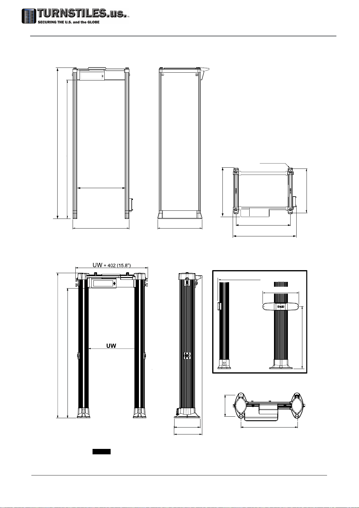
Due to its inherent natural construction the archway may be subjected
to slight deformation. A maximum 8 mm overall curvature of the
antenna still ensures unchanged performances.
Correct Use of the Device
A Metal Detector is a unit that reacts to the metal masses present on
people in transit.
As part of the normal screening process, people are required to walk
through the detector archway. A complete analysis requires a complete
passage through the archway.
Forbidden use of the Device
Any use different from that described in this manual is forbidden.
Operating limits
Refer to the ‘Specifications’ section.
Installation warnings
Observe current regulations regarding electrical and personal safety for
both the operator and the installer when installing the device.
Choose the installation site carefully. Avoid placing the device in
locations where it may be directly exposed to sunlight, in unventilated
areas or in places that are close to sources of heat. In addition, avoid
places that are subject to vibrations, dust, humidity, rain and
excessively high or low temperatures.
Installation must be carried out by qualified personnel. Given the
dimensions of the device, it is requested that the installation site be
kept clear while work is carried out to facilitate setting it up and to avoid
any harm to third parties.
Position the device as far away as possible from sources of
electromagnetic interference such as transformers or motors.
When installation is completed, the detector must be anchored to the
ground in a stable manner and not subject to vibrations (use expansion
screws inserted through the anchoring holes in the base of the panels).
All connecting cables between the gate and the power supply or other
external devices must be properly fixed and protected so as to achieve
the best performance from the detector and avoid accidental injury to
people who might trip over them.
Handle the device with care and without excessive force during
installation, use and maintenance.
Before powering up the device, check that the mains power supply
voltage corresponds to the voltage shown on the device's electrical
specifications plate. Verification that the power supply conforms to the
specified values plate and to the regulations in force is the total
responsibility of the customer.
The device should be connected to the mains voltage only after all the
connections required for full installation have been carried out.
The device must be connected to a power supply circuit fitted with a
switch or other device which allows the power to be cut off.
If the device is to be powered via an external autotransformer to
regulate the voltage, ensure that the common terminal of the
autotransformer is connected to the neutral of the power-supply circuit.
The power-supply plug must only be inserted into a socket fitted with
an earth/ground connection.
Any break in the safety conductor, either inside or outside the device,
or disconnection of the earth/ground safety terminal, will render the
device dangerous. Intentional cutting or disconnection is strictly
forbidden.
Whenever there is any suggestion that the level of protection has been
reduced, the device should be taken out of service and secured against
any possibility of unintentional use, and authorised service technicians
should be called.
The level of protection is considered to have been reduced when:
- the device shows visible signs of deterioration;
- the device does not operate correctly;
- the device has been stored for a long period in sub-optimal
conditions;
- the device has suffered mechanical or electrical stress (shocks,
bumps, etc..);
- the device has suffered severe stress during transport;
- the inside of the device has come into contact with liquids
Always remove the plug by hand when disconnecting the power supply
cable, never by pulling on the cable.
If the power-supply adapter is not waterproof: place it in a ventilated
position where it is protected from water (rain, condensation, liquid
detergents)! There is a risk of electric shocks for people and damage to
the equipment.
This device contains electrical and electronic components, and may
therefore be susceptible to fire. Do not install in explosive atmosphere
or in contact with inflammable material. Do not use water or foam in the
case of fire when the device is powered up.
To avoid damage due to lightning, fit the power supply line with
appropriate surge suppressors.
Do not use in an explosive atmosphere. Avoid contact with inflammable
or explosive material!
Medical Safety Information
The Metal Detectors comply with regulatory requirements for human
exposure to electromagnetic fields. THe manufacturer submits its devices
to testing by bodies qualified to check compliance with the emission limits
of the main standards currently in force (documentation available on
request). General information on use: the electromagnetic field emitted by
devices is extremely weak, with amplitude comparable with that of the
earth. However, the manufacturer cannot exclude that this device may
affect personal medical electronic devices, depending on their functionality
or their restrictions on use. Any recommendation or directive issued by
medical personnel or medical equipment manufacturers relating to
electromagnetic fields must therefore be implemented. If for any reason a
person about to pass through the detector shows fear or refuses to
undergo the inspection, it is recommended that the inspection be carried
out using an alternative method.
For further information on standard procedures to be followed for
inspection of people with implanted medical devices using a metal
detector, please consult the ASTM F2401-04 standard ‘Standard Practice
for Security Checkpoint Metal Detector Screening of Persons with Medical
Devices’ or other relevant directives.
Turnstiles.us is not responsible for direct or indirect harm to people or
things due to incorrect use of the Metal Detector.
Use warnings
The final user is responsible for selecting the appropriate security
level/sensitivity for their application. After this selection has been made,
and programming has been adjusted accordingly, it is also the final
user's responsibility to verify calibration using the test object(s)
appropriate to the level of security selected. Additionally, this test
should be carried out periodically (at least daily) to insure no changes
have occurred in the equipment. Reference Standards on this
argument include documents ASTM C 1270-97 and ASTM C 1309-97.
The execution of the test and its result shall be recorded. In case of a
negative result, the equipment should not be used.
The final user is responsible for determining and implementing the
appropriate inspection procedures and for the training of personnel
involved in carrying them out.
The information contained in this manual is provided only as a technical
reference for use and maintenance, and does not contain operational
procedures. For further information on standard procedures to be
followed for inspection of people using a metal detector, please consult
the guidelines entitled ‘The Appropriate and Effective Use of Security
Technologies in U.S. Schools’ by the National Institute of Justice or
other relevant directives.
Handle the device with care and without excessive force during use.
303-670-1099

4
In case of damage to the Power Supply Unit, input and output cables
included, the unit should be returned to qualified Technical Assistance
Centre or directly to Turnstiles.us for proper repair or replacement. Do
not open, tamper with or attempt to repair the power supply unit or any
other part of the device.
If the device is stored for a long period in temperatures outside the
operating range, wait for the temperature of the detector to come back
within that range before switching on
Whenever there is any suggestion that the level of protection has been
reduced, the device should be taken out of service and secured against
any possibility of unintentional use, and authorised service technicians
should be called.
The level of protection is considered to have been reduced when:
- the device shows visible signs of deterioration;
- the device does not operate correctly;
- the device has been stored for a long period in sub-optimal
conditions;
- the device has suffered mechanical or electrical stress (shocks,
bumps, etc..);
- the device has suffered severe stress during transport;
- the inside of the device has come into contact with liquids.
Always remove the plug by hand when disconnecting the power supply
cable, never by pulling on the cable.
The standard power-supply adapter is not waterproof: place it in a
ventilated position where it is protected from water (rain, condensation,
liquid detergents)! There is a risk of electric shocks for people and
damage to the equipment.
This device contains electrical and electronic components, and may
therefore be susceptible to fire. Do not install in explosive atmosphere
or in contact with inflammable material. Do not use water or foam in the
case of fire when the device is powered up.
Do not use in an explosive atmosphere. Avoid contact with inflammable
or explosive material!
Models with protection covers: make sure that a switch or other device
which allows the power to be cut off can be easily operated, as the
main switch of the device is not directly accessible.
Maintenance warnings
Carry out the periodic maintenance regularly (see section on
Maintenance).
Do not wash the device with water, liquid detergents or chemical
substances. Use a slightly moist, non-abrasive cloth for cleaning.
The device must be disconnected from all power sources before
undergoing any maintenance or cleaning, and before being moved.
Read the chapter ‘Maintenance’ carefully before calling the service
centre. Whatever the problem, only specialised service personnel
authorised to work with security equipment should be called.
Any damaged parts of the device should be replaced by original
components only.
Important advice regarding any batteries incorporated in the device.
- When replacing: use OEM spare parts or batteries with equivalent
electrical/mechanical characteristics.
- Do not open batteries: they may contain a small quantityof potentially
dangerous substances.
- Do not short-circuit the contacts: serious risk of burning and
breakage!
- Do not dispose of battery in fire: danger of explosion!
Any maintenance or repair involving the device being opened while
powered should be avoided as far as possible: if this becomes
inevitable, the operation must be carried out only by qualified personnel
who are fully aware of the risks involved.
Disposal warnings
Disposal of parts with environmental impact: follow the regulations in
force in the country where the device is being used.
Important advice regarding any batteries incorporated in the
device. When replacing: use OEM spare parts or batteries with
equivalent electrical/mechanical characteristics. Do not dispose of
used batteries in general rubbish bins; use public battery collection
facilities as per local regulations, or return them to a Turnstiles.us. If
the equipment is to be disposed of, remove the batteries and dispose
of them separately.
Harmlessness to Magnetic Media
The device is safe for items carried by people including all common
magnetic media such as magnetic cards floppy disks and tapes
(conforming to NIST - NBS 500-101 ‘Care and Handling of Computer
Magnetic Storage Media’).
Warranty conditions
The warranty on all products, extended to the period agreed with the Sales
Department, is applicable to goods supplied from our factory, and for every
constituent part thereof, with the exception of the batteries and the card
reader. Any form of tampering with the device, and in
particular opening its container, is strictly forbidden and will invalidate the
warranty.
Symbols The device is marked with this symbol whenever the operator or the maintenance personnel, in order to avoid possible
damage, have to refer to the present manual. The same symbol appears in the booklet at points where warnings or
particularly important instructions are given - instructions that are vital to a safe and correct use of the device.
The device is marked with this symbol in those areas where a dangerous amount of voltage is present. Only specialised
maintenance personnel should make adjustments in these areas.
This sign in the manual indicates tips for optimising the device’s performance.
This symbol printed on the packaging identifies operations that can be properly carried out after reading the related section
of the present manual.
Acronyms used in this document
MD Metal Detector
FAT Factory Acceptance Test Report: verification of the equipment compliance to the customer requirements at the end of the
manufacturing process
Revisions
Code Firmware Version Date Author Reference Changes
FI060K0092v1000 DF1B1000 2014-04-30 DTP-BC - First edition
FI060K0092v1100 DF1B1000 2014-09-19 DTP-BC - Added parameters LBI, EN, RAV, RAT; OTS executable at user level,
according to UP setting.
FI060K0092v1110 DF1B1000; DF1B1100 2014-12-05 DTP-BC - Panel models: assembly of options. Spare parts codes. Software codes.
FI060K0092v1200 DF1B1000; DF1B1100 2014-12-21 DTP-BC - Description of protection degrees. Notes for stabilizing plates. Battery
operation time.
303-670-1099

5
2DESCRIPTION
2.2 Composition
CU
5
1
2
3 45
1
2
34
plastic case metal case
PSA IP30 IP67
CU
TX
RX
Rf
C1
C2
PSA
Ph
AA
LBL
LCM
9
8UCM-RX
UCM-TX
7
6
10
11
UPC UPC
BAT UCM-TX
UCM-RX
LCM
11
Ph - Rf
P1
P2
R1
R2
LBL
Ph
TX RX
Rf
C1
LCM
PSA
UPC
UPC
CU
LBL
AA
9
UCM-RX
UCM-TX
8
7
6
10
UCM-TX UCM-RX
LCM LINE Ph - Rf
LBL
CU - Control Unit
The control unit, available in plastic casing or metal casing, is designed to be attached directly to
the crossbar of the archway. An embedded Infra-Red interface allows the use of an accessory
remote control unit which acts as the control unit keypad. It includes also a BLUETOOTHTM
interface for wireless connection to a PC for service operations. Parts of the control unit:
8-digit alphanumeric display, divided into two sections, the left part is green and the right one is red.
sounder
keypad for status reading and programming
slot of the chip card reader
security lock of the front panel
303-670-1099

6
PSA - Power Supply Adapter
Standard version: protection degree: IP30 (IEC60529).
Input voltage: 100-240 V~, -10% / +15%. Dimensions: 145mm x 76mm x 45mm (LxWxH). Weight: 0,9 kg. Cable length:
input side: 3m. output side: 2m. Available input plugs: CEE, UL 15P, UL l5-15P, UK.
OPTION]
Metal case sealed version: protection degree: IP67 (IEC60529). Input voltage: 100…240V ~, -10/+15%,
47…63 Hz. Dimensions: 210mm x 68mm x 40mm (LxWxH). Weight: 1.3 kg. Cable length: input side: 2m; output side:
2m. The input side cable is not fitted with plug, to allow passing it inside conduits.
AA - Archway
The archway consists of two treated panels or columns containing the windings and the
connectors to the control unit. A special protective boot renders the base of the archway
waterproof, and therefore fully insulated even in the event of wet floors.
Parts of the archway AA:
TX Transmitter antenna
UPC upper protection cover
LCM Lower Connection Module with on/off switch
UCM-TX Upper Connection Module of TX antenna
Ph Photocells for transit counting (options on column version). Two versions available: 2-
beam (standard) and 4-beam (high precision).
The photocell system is composed of two photocell modules (P1, P2), built into the
Transmitter Antenna, and two retroreflectors (R1, R2), built into the Receiver Antenna.
They allow counting of people passing through the archway.
LBL Label with reference data:
MODEL/TYPE Model
SERIAL NUMBER Serial Number
MAC address (with Ethernet interface only)
RX Receiver antenna
UPC upper protection cover
UCM-RX Upper Connection Module of RX antenna
Rf Reflectors for transit counting (options on column version)
C1 crossbar fitted with holes for mounting the control unit
C2 crossbar without holes (panel shape version)
K ON/OFF special key
Indicators and commands located in the archway
LINE power indicator (lit on when I/O switch is set to ‘I’).
additional power indicator
entry pacing lights: green light – enter the archway; red light - wait
zone indication light bar: in case of an alarm, the bar indicates the position of the metal
mass intercepted inside the archway.
I / O Anti-tamper on/off switch, activated using special key K
11 low battery sounder (only with emergency battery option)
Connections located in the archway
LCM Lower Connection Module:
30Vdc power-supply input connector
|0|0| 9-pin serial communication port (pin1: reserved, +30Vdc output; pin2: data in; pin3: data out; pin5:
ground; all other pins: reserved)
LAN Ethernet port (only with Web Server and Logger option)
type-A host USB port (only with Web Server and Logger option)
micro-B device USB port (reserved, only with Web Server and Logger option)
UCM-TX Upper Connection Module of TX antenna:
MD-TX control unit-antenna connections
CNT-TX auxiliary connector (for advanced functions)
PS/COM serial communication port and power supply input (identical to |0|0| port)
BAT emergency battery connector (panel shape version only)
RJ Ethernet port (with Web Server and Logger option installed, column-shape only)
USB port (with Web Server and Logger option installed, column-shape only)
CAM supply output for accessory devices (with Ethernet option installed, column-shape only)
UCM-RX Upper Connection Module of RX antenna:
MD-RX control unit-antenna connections
CNT-RX auxiliary connector (for advanced functions)
303-670-1099

7
[OPTION]
Emergency batteries Code: APSM2Plus/P (panel shape version only)
Two emergency batteries, included inside the Lower Connection Module, switch in automatically and allow the
independent operation in the event of mains power down. Typical operating time in battery mode is 30 minutes (time
varying with the presence of accessories and options). The batteries recharge automatically when the metal detector is
connected to the AC power supply and switched on. Recharge time is about 8 hours. The module provides an audible ‘flat
battery’ signal activated when the battery charge goes below the operational limit of the device (signal endurance: about
12 hours).
[OPTION]
Web Server and Logger
Code: APSIM2Plus/P or APSIM3Plus/P (panel shape version); APSIM2Plus/E or APSIM3Plus/E (column shape version).
This module provides the following additional functions:
-Built-in 10/100 base T Ethernet LAN interface
-Web server for set-up and remote data log
-Real/Time clock with battery backup
-Non-volatile Memory for Metal Detector events storage.
-wireless Wi-Fi interface (APSIM3Plus version only)
-support of NetID system (APSIM3Plus version only)
[ACCESSORY]
Long Life Crossbar Battery Back-Up (panel-shape version only)
Code: 55681. This Battery Pack (BC in the figure) can be attached to the crossbar of the archway. Two 9Ah batteries switch in
automatically and allow the independent operation in the event of mains power down. Typical operating time in battery mode is 9
hours (time varying with the presence of accessories and options). The batteries recharge automatically when the metal detector
is connected to the AC power supply and switched on. The battery charger is included in the Lower Connection Module and
provides an audible ‘flat battery’ signal activated when the battery charge goes below the operational limit of the device (signal
duration: about 12 hours).
REMARK: this option is not available for the Weather Resistant and Water Proof configurations.
BC
303-670-1099

8
Configurations with different protection degrees
Standard Configuration
Intended use: indoor use.
The standard configuration is based on a control unit in plastic case and a power supply adapter
for indoor use only.
OPTION]
Versions with protection covers
Anti-Vandalism
Configuration
Intended use:
• indoor use
This option includes a
stainless steel control
unit and a water proof
power supply adapter in
metal case.
Connection s of power
supply and antenna are
also protected by covers
equipped with screws
requiring tools for
removal.
Weather Resistant
Configuration
Intended use:
• sheltered use
This configuration is
intended for upgrading
the standard version to
outdoor applications
according to IEC 60950-
22.
This kit includes
shelters, crossbar,
protection covers for
power supply and
waterproof power supply
adapter.
IP65 Configuration
Intended use:
• outdoor sheltered permanent installations, or
• outdoor non-sheltered short-term installations (single event entrance).
This configuration provides IP65 Control Unit, IP 67 Power Supply Adapter, anti-vandalism protections and a weather
proof archway structure compliant with IEC 60950 Standard, Part 22. All archway connections are also protected by
covers equipped with screws requiring tools for removal. Special covers, designed to protect the gate against the
exposure to water arriving from any direction, allow the WTMD to operate in severe environmental conditions.
303-670-1099

9
2.3 Specifications
Power Supply: 100…240V~ -10/+15%, 47…63Hz, 40VA typical (consumption can vary according to accessories/options
installed). Installation category: II (IEC61010-1); Pollution degree : 2 (IEC61010-1).
Operating temperature: -20°C to +70°C (on demand: -37°C to +70°C); Storage temperature: -37°C to +70°C
Relative humidity: 0 to 95% (without condensation)
Standard Version
UW +115 (4.5”) UW +50 (2”)
630.00 (24” 3/4)
ø6.5 (1/4”)
UW
2255 (88.8”)
2050 (80.7”)
711 (28”)
UW +156 (6.2”)
660.00 (26”)
2040 (80.3")
2255 (88.8")
401(15.8”)
340 (13.4”)
UW +155(6.1”)
990 (39")
560 (22”)
UW+ 362 (14.3”)
Dimensions: UW = 720mm (
[OPTION]
: 760mm or 820mm (panel shape version); 820mm (column shape version))
303-670-1099

10
Version with protection covers
2255 (88.8”)
776 (30.6”)
630 (24.8”)
ø6.5 (1/4”)
2050 (80.7”)
UW +115 (4.5”) UW +50 (2”)
UW +170 (6.7”)
UW
660.00 (26”)
340 (13.4”)
UW +155(6.1”)
2035 (80.1")
2275 (89.6")
401(15.8”)
440(17.3”)
990 (39")
560 (22”)
UW+ 362 (14.3”)
Dimensions: UW = 720mm (
[OPTION]
: 760mm or 820mm (panel shape version); 820mm (column shape version))
303-670-1099

11
3INSTALLATION
Before proceeding to install the device read the warnings and instructions in this section and in the paragraph
‘Installation, use and safety information’ carefully. Please note that Turnstiles.us is not responsible for any
damage that may result from installations that do not follow these guidelines.
3.1 Preliminary layout inspection and positioning
General Rules
Transit requirements The Metal Detector will be positioned, according to the requirements
dictated by the transit, in such a way as to allow the maximum flow of people and observance
of the rules for installation.
Minimum distances - Electrical and mechanical compatibility Move any possible source
of electrical/electronic interferences in general away from the metal detector probe: the
distance depends on the type and power of the device and on the setting of the Metal
Detector. The following examples describe some relevant aspects related to the presence of
an X-Ray Unit installed close to the Detector.
Choosing the installation place according to the equipment protection degree.
Standard and Anti-Vandalism configuration: indoor applications.
Weather resistant configuration: this configuration can be applied in
outdoor sheltered installation where occasional rain can occur.
IP65 configuration This configuration can be applied in outdoor sheltered
permanent installations or outdoor non-sheltered short-term installations
(single event entrance).
3.1.1 Examples of possible sources of interference
TX
RX
2
4
1
3
D2
D1
11
9
8
7
612
D3
10
4
5
Typical Layout of Access Point equipped with an X-Ray Unit
Recommended minimum distance
Sensitivity Level/
Object Size Class
D1
Radiating source
(ex.: CRT monitor, switch-
mode power supply)
D2
Large fixed metal mass
(ex.: X-Ray Unit, metal
furniture, metal wall)
D3
Large moving metal mass
(ex.: metal door, metal cart)
Large Object Size 60 cm (2 ft) 40 cm (1.3 ft) 100 cm (3.3 ft)
Medium Object Size 100 cm (3.3 ft) 70 cm (2.3 ft) 150 cm (5 ft)
Small Object Size 150 cm (5 ft) 100 cm (3.3 ft) 200 cm (6.6 ft)
All numeric distances indicated in this paragraph are indicative and depend on the detection
performance required by the specific application and on the nature or extent of the source of interference.
The X-ray unit is in the immediate vicinity of the MD and may provide several sources of
interference:
- the monitor (electrical interference)
- the conveyor belt motor (electrical interference)
- the mechanical components of the conveyor belt (mechanical interference). Example:
metal side-panel not firmly fixed.
The higher the required security level is, the stronger the influence of the above mentioned
sources might be.
1 MD centring with respect to the X-ray unit
Centre the MD with respect to the X-ray unit, as illustrated in the figure.
303-670-1099

12
When the Metal Detector is centered with respect to the areas where luggage and metal
personal effects are deposited or recovered, these objects are unlikely to move close to the
device and cause alarms.
2 MD orientation
The archway must be positioned with the TX antenna on the side of the X-ray unit. This layout
places the RX antenna - that is most sensitive part of the archway - as far as possible away from
the potential sources of electrical interference contained into the X-ray unit (mainly the monitor
and the conveyor belt motor).
NOTE: with this configuration, the power supply socket for the MD must be on the X-ray unit side.
3 Distance between the MD and the X-ray unit
Check the distance between the TX panel and the X-ray unit (refer to table ‘Recommended
minimum distance’ above).
4 X-ray unit anchoring
The X-ray unit must be firmly anchored to the floor to prevent its mechanical parts from
vibrations.
5 Sources of vibration:
Strong gusts of air: remove the cause (f. i., a door slam), if possible. EVA procedure
(see EVA programming command) can be carried out to compensate vibrations.
Objects, panels or furniture in direct contact with the MD: no objects, panels or
furniture shall be placed in direct contact with the MD.
6 Sources of vibration: Unstable Floor
The MD gate shall be anchored to a stable floor. Avoid installing on wood or metal platforms
unless necessary. In this latter case, contact CEIA for additional information
7 Anchoring the MD to the floor
ATTENTION: this step must be performed only once the setting and the environmental interference level
have been tested and found to be compatible. Refer to ‘Anchoring the MD to the floor’ section for details.
The MD must be firmly anchored to the floor.
8 ‘Fixed’ metal masses
Any large object positioned close to the MD shall be only made of plastic or other non-metallic
material (refer to table ‘Recommended minimum distance’ above).
9 Moving metal objects
Doors or other large structures made of metal shall be kept far from the MD (refer to table
‘Recommended minimum distance’ above).
10 Low-power Electrical/Electronical Devices
The distance between the MD RX antenna and electric/electronic devices should be greater than
1 m (3.3 ft).
11 High-power electrical conductors and Electrical/Electronical Devices
These sources should be as far as possible from the MD RX antenna.
12 Distance between the MD and the Security Screener in charge
The position predisposed for the Security Screener in charge should not cause the MD to detect
his own metal objects (i.e. transceivers). Suggested distance is 0.5 m (20’) minimum.
303-670-1099

13
3.1.2 Multiple installation
In case of the installation of multiple units it is necessary to respect the following rules, in order to
synchronize each unit with the other ones.
Place the MDs following the sequence: TX-RX - RX-TX - TX-RX ...
Ensure that the distances (‘d1’ and ‘d2’ in the figure below) between the MDs are not less
than the minimum required.
Xray
unit 1
Xray
unit 2
>d1
RX RX TXTX
d1 = 5cm
MD4
Xray
unit 3
MD3
RXTX RX TX
Xray
unit 1
MD1
RX
TX
Xray
unit 2
MD2
RX TX
>d1 >d1
>d2
d1 = 15cm, d2 =100 cm
Enter programming and set a different channel (CH) on each MD, according to its position
(this can be performed during the OTS procedure, see the following steps).
3.2 Installation procedure overview
Personnel needed
Two qualified installers or more and one authorised Security Representative
Knowledge required
Some MD working parameters: refer to the ‘Programming’ section
Operating requirements established by the Security Authority
Components needed
Unpacking: Scissors and Pliers
Phillips screwdriver n.1
Kit C.E.I.A. FGA & TFV ()
Metal-free clothes (Clean Tester): Tracksuit, Gym shoes, No metal personal effects (metal cases, metal
watch, …)
Anchoring to the floor by means of screws: drill, ratchet tightener (socket wrench) , expansion anchor
with Nr. 12-24 (or M6) screw
Tools for Verification of the Calibration (reference test pieces, …)
3.3 Assembly
Please note that Turnstiles.us is not responsible for any damage that may result from installations
that do not follow these guidelines.
Holes It is strictly forbidden to make holes in the Metal Detector antenna or to insert screws in
positions, or of lengths, not expressly indicated by Turnstiles.us. Damage due to such actions is not
covered by the product warranty.
3.3.1 Assembly rules
The control unit CU has to be mounted on the crossbar on the exit side of the gate, as it provides
the screener with the alarm signals.
The crossbar C1, fitted with holes for mounting the control unit CU, must be placed so that the
control unit is located on the exit side of the gate.
303-670-1099

14
The part TX, including the lower connection panel LCM, must be placed facing the available
power supply outlet.
According to the previous rules, the archway can be assembled in two different configurations
(Configuration A or Configuration B), swapping the position of the TX and RX parts.
Configuration A Configuration B
XRU
XRU XRU
XRU
Configuration A Configuration B Configuration A Configuration B
Typical application fitted with two Metal Detectors and two X-Ray Units
It is recommended that the archway is assembled on the floor, in horizontal position. Whenever needed,
and specifically when lifting up the assembled archway from the floor and moving it to the final location,
two or more people are mandatory.
303-670-1099

15
3.3.2 Assembly Procedure of the Panel-Shape Version
PSA
vt
AW1
AW2
ck
K
cf
vc cbc
vc cbc
TX1
IK
cp
ccp
PC cmp
TX TX antenna
RX RX antenna
C1 Crossbar fitted with holes for
mounting the control unit
C2 Crossbar without holes
CU Control unit
PSA AC/DC power supply adapter
IK Installation kit:
AW1 Allen wrench for crossbar
AW2 Allen wrench for control unit
cbc cap for crossbar fixing holes
cf key of control unit lock
ck screwdriver for upper connectors
K on/off key
vc control unit mounting screw
vt crossbar fixing screw
PC Protection covers:
cmp protection cover of the
lower connection
module
ccp protection cover of CU
control unit and C1
crossbar
cp protection cover of C2
crossbar
Pictures of main components
Positioning the panels
Tilt down the packaging containing the archway panels.
Place S1 and S2 spacers on the floor as illustrated in the figure below.
Extract the upper panel (TX) from the packaging and place it on the S1 spacer, making sure that
its internal side is facing the packaging .The internal side of each panel is identified by the three
holes in the cross-bar mounting area (detail D1).
Extract the lower panel (RX) from the packaging and place it on the S2 spacer, making sure that
its internal side is facing the other panel (detail D2).
TX
D1
TX
RX
D2
S2
S1
S1 S2
303-670-1099

16
Attaching the crossbars
ATTENTION! The crossbars must be attached to the panels, according to the suitable
configuration.
[OPTION]
Version with Long Life Crossbar Battery
Back-Up: attach the Battery Compartment to the C2
crossbar, before assembling it with the panel.
Extract the crossbars from the packaging.
Configuration A (with TX panel on the left when facing the exit side)
Attach the C1 crossbar with holes to the lower part of the panel, taking care that the logo is
facing the floor.
Attach the C2 crossbar with no holes to the upper part of the panel, making sure that the logo
is facing up.
RX
C1
C2
Configuration B (with TX panel on the right when facing the exit side)
Attach the C2 crossbar with no holes to the lower part of the panel, taking care that the logo
is facing the floor.
Attach the C1 crossbar with holes to the upper part of the panel, making sure that the logo is
facing up.
RX
C2
C1
Secure the crossbars to one of the panels, using vt screws and AW1 Allen key (included in the
installation kit). Tightening torque: 10 Nm.
RX
303-670-1099

17
Approach the other panel and attach the crossbars, using vt screws and AW1 Allen key.
RX
TX
TX
d
d
Attaching the control unit
Remove the protection caps of the panels, to access the inner connectors.
[OPTION]
NOTE: the protection caps of the standard protection degree
configuration are fitted with locking knobs. For higher protection degrees, the
knobs are replaced by screws: use Allen key AW2 or TX1 to free them.
Configuration A
Lift the archway, placing it on the supports S1 and S2 Attach the control unit to the lower
crossbar, using vc screws and AW2 Allen key (included in the installation kit). Tightening torque:
1.2 Nm. Cover the entry side of the fixing holes with the cbc caps.
cbc
vc cbc
cbc cbc
cbc
Configuration B
Attach the control unit to the upper crossbar, using vc screws and AW2 Allen key (included in the
installation kit). Cover the entry side of the fixing holes with the cbc caps. Tightening torque: 1.2
Nm.
cbc
vc cbc
cbc
cbc cbc
S2
S1
S1
303-670-1099

18
cK
Connecting the control unit
Connect the cables coming from the control unit to the panels, taking care to match the labels of
each cable connector with the corresponding panel connector.
Lock the cable connectors, using the short screwdriver cK included into the
installation kit. Insert the cables into the crossbar groove. Fix the cables in
position using the clips on the panels. Wind the cable in excess, if necessary.
Remount the protection caps.
BAT
Configuration A
TX RX
“MD-TX”
“MD-RX”
RX RX
Configuration B
TX RX
“MD-TX”
“MD-RX”
RX
RX
303-670-1099

19
BAT
[OPTION]
Version with Long Life Crossbar Battery Back-Up
Connect the cable coming from the battery compartment to the 2-pole connector
(BAT) located close to the 9-pole D-Sub “PS/COM” connector of the TX panel.
[OPTION]
Version with protection
covers
Insert caps csp into the grooves
of the panels, located close to the
crossbar C2. Each cap s secured
by a short cord to a cable clip.
Remount covers cp .
Attach the protection cover ccp of the crossbar C1, using
the hooks h and the knobs vp, taking care to push it
towards the panel covers cp.
Attach the protection cover tp of the crossbar C2, using
the hooks h and the knobs vp, taking care to push it
towards the panel covers cp ccp cp
.
vp
h
vp
h
vp
h
Lifting the archway up
Lift up the assembled archway from the floor.
Remark: it is mandatory that this operation is performed by two or more people!
303-670-1099

20
3.3.3 Assembly Procedure of the Column-Shape Version
PSA
pcc AW1
AW2 K
cf
vc cbc
vc cbc
PH
IK
ccp
PC
TX TX antenna
RX RX antenna
C1 Crossbar fitted with holes
for mounting the control
unit
vt crossbar fixing screw
CU Control unit
PSA AC/DC power supply
adapter
IK Installation kit:
AW1 Allen wrench for crossbar
AW2 Allen wrench for control unit
cbc cap for crossbar fixing holes
cf key of control unit lock
ck screwdriver for upper connectors
K on/off key
pcc cap for photocell connections cover
PH Phillips screwdriver (photocell)
vc control unit mounting screw
PC Protection covers:
ccp protection cover of
CU control unit and
C1 crossbar
Pictures of main components
Positioning the columns
Place F spacers on the floor as illustrated in the figure below.
Extract one column from the packaging and place it on the Fspacers.
Extract G supports from the packaging and place them on the floor as illustrated in the figure
below. Place the column on the G supports.
Extract the second column from the packaging and place it on the F spacers.
Extract Gsupports from the packaging and place them on the floor.
Place the TX - RX columns as illustrated in the figure below (connection module of the base
facing the ceiling).
RX
TX
RX
TX
303-670-1099
This manual suits for next models
9
Table of contents