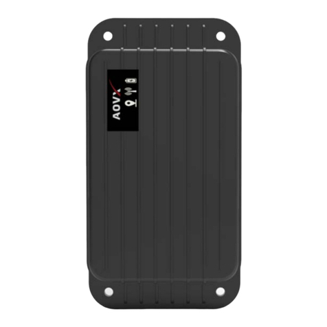
Locosys RTK-M100 User manual

RTK
-
M100
M100
User’s Manual
© 2020 LOCOSYS Technology Inc.
User’s Manual
www.locosystech.com

RTK-M100 User’s Manual
Page 1of14
Document history
Version Date Updates
1.0 May 31, 2020 Creation.

RTK-M100 User’s Manual
Page 2of14
Contents
1.
INTRODUCTION ................................................................................................................................................... 3
2.
F ATUR .............................................................................................................................................................. 3
3.
APPLICATION ....................................................................................................................................................... 3
4.
HARDWAR D SCRIPTION ................................................................................................................................... 4
4.1.
BLOCK DIAGRAM ............................................................................................................................................ 4
4.2.
TH RN T CONN CTOR .................................................................................................................................. 4
4.3.
MINI USB CONN CTOR.................................................................................................................................... 4
4.4.
MICRO SD CONN CTOR ................................................................................................................................... 4
4.5.
I/O CONN CTOR ............................................................................................................................................. 4
4.6.
S RIAL PORT CONN CTOR............................................................................................................................... 5
4.7.
RF CONN CTORS OF RTK ANT NNA ................................................................................................................ 6
4.8.
RF CONN CTOR OF 4G/LT .............................................................................................................................. 6
4.9.
L D ................................................................................................................................................................. 6
5.
INSTALLATION OF SIM CARD ................................................................................................................................ 6
6.
G TTING START D ............................................................................................................................................... 7
7.
CONFIGURATION XAMPL S ................................................................................................................................ 8
7.1 CONFIGURATION XAMPL OF TH ROV R ...................................................................................................... 9
7.2 CONFIGURATION XAMPL OF TH BAS STATION .......................................................................................... 12
8.
RTK N TWORK .................................................................................................................................................... 14

RTK-M100 User’s Manual
Page 3of14
1. Introduction
RTK-M100 system pro uct is ual-frequency multi-constellation RTK evices, Embe e
NXP® i.MX 6 (Automotive Gra e) high-en processor an provi es centimeter-accurate GNSS
measurements. All of them can work in base station or rover. There are two communication
interfaces, inclu ing Ethernet, 4G/LTE. Through these built-in communication functions for
local or coul ata center communication with the external host.
RTK-M100 system have not only 64M bytes on-boar flash memory for saving up to 7 ays
of RTK position ata, but also a micro SD interface to log RTK position ata an GNSS raw ata
for post processing. In a ition, light weight an low power consumption make RTK-M100
pro uct series easy to use.
2. Feature
•Embe e NXP® i.MX 6 (Automotive Gra e) processor.
•LOCOSYS Centimeter-accurate RTK mo ule.
•LOCOSYS RTK algorithm.
•Support Multi-frequency an Multi-constellation.
(GPS, BEIDOU, GLONASS, GALILEO an QZSS)
•Up to 5Hz RTK position.
•Up to 2Hz simultaneous RTK position.
•Built-in RJ-45 Ethernet function.
•Built-in 3G/4G-LTE mo em.
•Built-in NAND flash、LPDDR2、Power management.
•Micro-SD、CAN-Bus interface、Micro-SIM hol er.
•Light weight an low power consumption.
•Embe e Linux OS.
3. Application
•Precision agriculture
•Environmental an structural monitoring
•Lan survey, 3D mapping an aerial photography
•Base Station or Rover use

RTK-M100 User’s Manual
Page 4of14
4. Hardware description
4.1. Block diagram
4.2. thernet connector
The pro uct oes not support the hot plug of Ethernet. If Ethernet is going to be use ,
please insert Ethernet cable before turning on the power of the pro uct.
4.3. Mini USB connector
The pro uct is powere through Mini USB connector. PC’s USB port, 5V power bank or
5V/1A a aptor can power the pro uct. Mini USB connector is also use for communication with
PC’s software tool RTKFox. The optional internal battery of the pro uct is charge through Mini
USB connector, too.
4.4. Micro SD connector
The pro uct supports hot plug of micro SD car with FAT32, ex: FAT or NTFS file system. The
user can save RTK position ata an GNSS raw ata to micro SD car for post processing.
4.5. I/O connector
The 8-position I/O connector of the pro uct is compatible with Hirose’s DF13 series. The
pin escription of the connector is in the following.
Pin 1: CANL, CAN Low-Level Voltage I/O.
Pin 2: CANH, CAN High-Level Voltage I/O.
Pin 3: GND, groun .

RTK-M100 User’s Manual
Page 5of14
Pin 4: IO_PWR, power input for IO pin 1 ~ 4. Input voltage range is 3.3V~5.5V.
Pin 5: IO_01, general purpose IO pin 1. Logic level is base on the voltage of IO_PWR.
Pin 6: IO_02, general purpose IO pin 2. Logic level is base on the voltage of IO_PWR.
Pin 7: IO_03, general purpose IO pin 3. Logic level is base on the voltage of IO_PWR.
Pin 8: IO_PWM, general purpose IO pin 4.Logic level is base on the voltage of IO_PWR.
4.6. Serial port connector
The external host CPU can communicate with the pro uct through the serial port. The
protocol is 115200-8-N-1 (115200 bau , 8 ata bits, no parity, 1 stop bit). The 6-position
connector of the serial port is compatible with Hirose’s DF13 series. The pin escription of the
connector is in the following.
Pin 1: NC, not connecte .
Pin 2: TX, transmit ata to the external evice. (3.3V)
Pin 3: RX, receive ata from the external evice. (3.3V)
Pin 4: NC, not connecte .
Pin 5: PPS, pulse per secon .
Pin 6: GND, groun .
TX an RX signals of the serial port an USB-UART bri ge IC connect to the same UART port
of the pro uct’s internal CPU mo ule. If both serial port an Mini USB connector are connecte ,
the serial port will ominate the communication with the internal CPU mo ule.

RTK-M100 User’s Manual
Page 6of14
4.7. RF connectors of RTK antenna
The pro uct supplies the e icate 3.3V power to the external GNSS antennas through RF
connectors of RTK mo ule. It has built-in antenna short circuit protection. The pro uct can
etect RTK antenna connection status. If RTK antenna is not properly connecte , green LED will
be always on.
4.8. RF connector of 4G/LT
Connect 4G/LTE antenna before turning on the power of the pro uct. If the pro uct
successfully registers to the network of the telecom provi er, the yellow LED will blink once
every secon .
4.9. L D
The pro uct has three LEDs. The colors are re , yellow an green. Detail escription is in
the following table.
L D State Description
Red Blink (on/off: 500ms) The pro uct is working.
Yellow
Blink (on/off: 500ms) Successfully register to the network of the telecom provi er
through 4G/LTE.
Blink (on/off:250ms) Not register to the network of the telecom provi er through
4G/LTE
Green
Always on RTK antenna is not properly connecte .
Blink (on/off:100ms) Data log function has been enable , but fails to etect the
micro SD car or internal flash memory is full.
Blink (on/off:300ms)
•Rover mo e: RTK fix is not available.
•Base station mo e: Survey-In is not complete.
Blink (on/off:500ms)
•Rover mo e: RTK fix.
•Base station mo e: Survey-In is complete.
5. Installation of SIM card
First, power off the pro uct an confirm the re LED is off. Then remove 8 screws of the
pro uct an pull out the PCB boar . The SIM car hol er is on the bottom si e of the PCB
boar shown as below picture. Prepare a micro SIM car with no PIN lock, an insert into SIM
car hol er. Then put PCB boar back into the metal box of the pro uct an tighten the screws.
Now SIM car is installe .

RTK-M100 User’s Manual
Page 7of14
6. Getting started
1. Install USB river for MS Win ows. It can be ownloa e at
http://www.prolific.com.tw/UserFiles/files/PL2303_Prolific_DriverInstaller_v1200.zip.
2. If Ethernet is going to be use , plug in Ethernet cable before power on the pro uct.
3. If 4G/LTE is going to be use , insert a micro SIM car with no PIN lock as escribe in the
section 5. Attach 4G/LTE antenna.
4. Connect Mini USB cable to the pro uct an the computer. A COM port will be enumerate
in the Device Manager of MS Win ows.

RTK-M100 User’s Manual
Page 8of14
5. Press the re button to power on the pro uct. The re LED of the pro uct will be on
imme iately. Wait for up to 1 minute until the re LED blinks. The pro uct starts an rea y
for control.
6. Now you can run PC software tool RTKFox to evaluate the pro uct.
7. Configuration examples
RTK-M100 pro uct series can work in three ifferent mo es, inclu ing rover, base station
an sensor mo e. The user can use PC software tool RTKFox to configure. After finishing the
steps in section 6, RTKFox starts as below. Select COM port that the pro uct is connecte .
If RTKFox connects to the pro uct successfully, all buttons are enable as below.

RTK-M100 User’s Manual
Page 9of14
7.1. Configuration example of the rover
Click the ra io button of “Rover” to show the setting page as below picture.
7. Click the selection “Position Mo e”. There are three options. The option “kinematic” is
for RTK position. The option “Moving baseline” is for RTK hea ing. The option
“kinematic + moving baseline” is for simultaneous RTK position an RTK hea ing.
8. Click the selection of “Up ate Frequency” to set the up ate rate of RTK.
9. Input the settings of NTRIP Caster.
10. Click the button “Apply” to take effect. The settings will be save in the internal flash
memory.
11. Check 4G/LTE connection by clicking “Network” button. If the pro uct registers to the
network of the telecom provi er, it will show “Connecte ” as below picture.

RTK-M100 User’s Manual
Page 10of14
12. Click “Satellite Info” button to check the receive GNSS signal strength. Most signals
shoul be higher than 40. If you want to see satellite information from the
reference/base station, you can click “Display” button an select “Rover & Base”.

RTK-M100 User’s Manual
Page 11of14
13. Click “Monitor Status” button. If “bps of NETWORK” varies, the connection to NTRIP
Caster is establishe an the correction ata for RTK is receive .
14. Click “Solution Result” button. You can see RTK fix or not an the other information of
RTK position.

RTK-M100 User’s Manual
Page 12of14
7.2. Configuration example of the base station
Click the ra io button of “Base Station” to show the setting page as below picture.
1. If the position of the pro uct is known, select “LLH” an input its latitu e, longitu e an
height. If the position is unknown, select “Survey In” to let the pro uct get its own
position that accuracy is 2~5 meters epen ing on the receive GNSS satellite signals.
2. Click the button “Apply” to take effect. The settings will be save in the internal flash
memory.

RTK-M100 User’s Manual
Page 13of14
3. Check 4G/LTE connection by clicking “Network” button. If the pro uct registers to the
network of the telecom provi er, it will show “Connecte ” as below picture.
4. Click “Satellite Info” button to check the receive GNSS signal strength. Most signals
shoul be higher than 40.

RTK-M100 User’s Manual
Page 14of14
5. Click “Monitor Status” button. If “bps of Output Streams” varies, the ata is successfully
transmitting to NTRIP Caster.
6. The configuration of the base station is one.
8. RTK network
Most countries have Continuously Operating Reference Stations (CORS) operate by the
government or enterprises. The stan ar protocol calle NTRIP is a opte to access these RTK
ifferential corrections. RTK-M100 pro uct have 4G/LTE mo em an support NTRIP that can
access these corrections to achieve centimeter RTK accuracy.
Table of contents
Other Locosys GPS manuals

