Loepfe WEFTMASTER FALCON-i User manual

WEFTMASTER ®
FALCON-i
Optical Yarn Defects Sensor
Fitting and Service Manual
46875003 en
Version 1.02 / 05.2014


Loepfe Brothers Ltd.
Kastellstrasse 10
P. O. Box
8623 Wetzikon/Switzerland
Phone +41 43 488 11 11
Fax +41 43 488 11 00
E-Mail service@loepfe.com
Internet www.loepfe.com
Document: WM_FALCONi_Fitting_46875003_en
Review status: Version 1.02
Date: 05.2014
This instruction manual is copyrighted and exclusively meant
for internal purposes.
Disclosures to any third party or reproduction of any kind –
even in form of excerpts – as well as the use and/or disclosure
of the contents without written approval from Loepfe Brothers
Ltd., except for internal use, are prohibited.
WeftMaster®and FALCON-i are registered trademarks of
Loepfe Brothers Ltd. for Switzerland and other countries.
© 2014 Loepfe Brothers Ltd., Switzerland


5
FALCON-i
Table of Contents
Table of Contents
1 General 7
1.1 About this Manual 7
1.2 Explanation of Symbols 7
1.3 Liability 8
2 Safety 9
2.1 Responsibilities 9
2.2 Personnel Requisitions 9
2.3 Usage 9
3 Installation and Start-up 11
3.1 General 11
3.2 Safety 11
3.3 Connections 12
3.4 Connection Diagram 12
3.5 Mounting and Adjustment 13
3.6 Possible Mounting Positions 14
4 Service 15
4.1 Safety 15
4.2 Servicing 15
5 Technical Data 17
6 Spare Parts 19


7
General
FALCON-i
For your safety in case of any insecurity, please contact your
supplier.
1 General
1.1 About this Manual
1.1.1 General This manual assures a safe and efficient handling of the optical yarn defects
sensor FALCON-i.
1.1.2 Obligation to Read The personnel is obligated to read and understand these instructions,
specifically the safety instructions, prior to all works.
1.1.3 Depository This manual is an integral part of the optical yarn defects sensor FALCON-i
and must be deposited within striking distance to the installation and avail-
able to the personal at all times.
In case of a resale of the installation this manual must be included.
In these instructions, safety information is marked with symbols and signal
words which point out the extent of the hazard.
The safety information has to be strictly observed to prevent accidents, per-
sonal injuries and damage to property.
1.2 Explanation of
Symbols
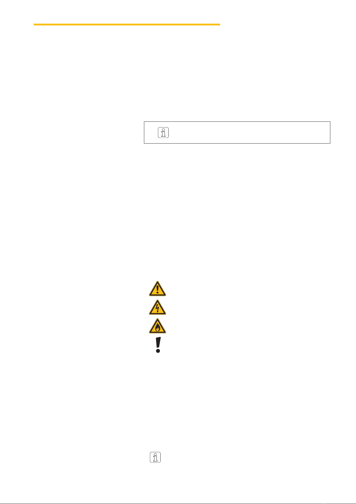
1.2.1 Symbols General hazard
Electrical hazard
Flammable
Property damage
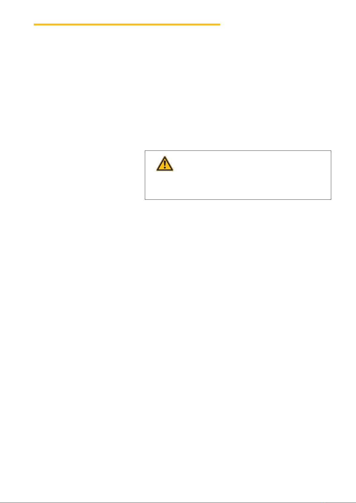
DANGER Indicates an imminently hazardous situation
which will result in death or serious injury.
WARNING Indicates a potentially hazardous situation
which could result in death or serious injury.
CAUTION Indicates a potentially hazardous situation
which may result in minor or moderate injury.
ATTENTION Indicates a potentially hazardous situation which may result
in damage to property.
1.2.3 Signal Words
1.2.2 Tips and Hints Useful tips and recommendations

8
General
FALCON-i
1.3 Liability
Information and safety instructions within this manual have been implement-
ed under consideration of valid standards and guidelines as well as the cur-
rent state-of-the-art based on our long-standing experience.
1.3.1 Information within
this Manual
1.3.2 Delivery Besides the contractual obligations terms of business and delivery by the
supplier apply.
1.3.3 Technical
Modifications
Loepfe Brothers Ltd. herewith excludes liability for damages and accidents
due to following occurrences:
Unauthorized rebuilds or modifications of the optical yarn defects sensor
Usage of unauthorized spare parts / reproductions / modification parts not
provided by Loepfe Brothers Ltd.
1.3.4 Improper Application or
Usage
Loepfe Brothers Ltd. herewith excludes liability for damages and accidents
due to following occurrences:
Usage not according to intended purpose of the equipment
Failure to observe the information given within this operation manual
1.3.5 Inadequate
Maintenance
Loepfe Brothers Ltd. herewith excludes liability for damages and accidents
due to following occurrences:
Deferred or inadequate maintenance
Not following the instructions described in chapter “Maintenance”

9
Safety
FALCON-i
Inadequate qualifications may cause serious injury
and material damage!
ZInstallation, operation and maintenance shall only be con-
ducted by qualified technical staff.
WARNING
2 Safety
2.1 Responsibilities The customer must rule the responsibilities for installation, operation and
maintenance of the optical yarn defects sensor FALCON-i and appoint rele-
vant persons in charge.
2.2 Personnel Requisitions
2.2.1 Inadequate
Qualifications
2.2.2 Qualified Personnel Following qualifications are listed in this manual for the different task areas:
Foreman and User are qualified and trained staff for the operation and
maintenance of the optical yarn defects sensor.
Installation Engineer and Service Engineer are qualified personnel
being familiar with all safety checks, installation and service guidelines.
Repair Technician is a qualified and trained employee of Loepfe
Brothers Ltd. or a technician specifically appointed therefore by Loepfe
Brothers Ltd.
2.3 Usage
2.3.1 Designated Use The optical yarn defects sensor FALCON-i is designed and constructed for
the detection of yarn defects, knots, loops and impurities in weaving.
The optical yarn defects sensor FALCON-i must be installed and operated
in compliance with the provisions listed in installation and operating instruc-
tions.


11
Installation and Startup
FALCON-i
Risk of injuries!
Work on the running machine may lead to severe personal
injury.
ZStop the machine and wait until the machine has come
to complete standstill.
ZOnly perform work on electrical components when these
are switched off, disconnected from the mains and po-
tential-free.
ZPrior to start-up verify if all appropriate covers are
mounted.
ZPrior to start-up perform safety check.
WARNING
3 Installation and Startup
3.1 General
3.2 Safety Installation and start-up may only be performed by authorized and trained
personnel.
Yarn guide
Yarn guide
Digital display
Sensor
Function button
Yarn guide ceramic

12
Installation and Startup
FALCON-i
Plug M8
male
(front view)
brown
black
white
PNP-Output
(I = 2.7 mA constant)
blue GND
800ms
6..8ms
24VDC
NPN-Output
(I Max. = 25 mA)
3.3 Connections
3.4 Connection Diagram
Plug M8
male
(front view)
brown
black
white
PNP-Output
(I = 2.7 mA constant)
blue GND
800ms
6..8ms
24VDC
NPN-Output
(I Max. = 25 mA)
Risk of fatal injury from electric current!
ZExternal circuits shall be double insulated from mains.
DANGER

13
Installation and Startup
FALCON-i
3.5 Mounting and
Adjustment
When mounting the optical yarn defects sensors FALCON-i, the following
must be observed:
Do not position the equipment such that it is difficult to disconnect the
M8 plug.
The yarn should run as smoothly as possible through the sensor.
The yarn must be slightly deflected by the white ceramic yarn guide (1).
By moving the outer yarn guide (2), an additional yarn calming can be
achieved.
12 2

14
Installation and Startup
FALCON-i
3.6 Possible Mounting Positions
Cone
Prewinder
Weft sensor

15
Service
FALCON-i
The sensor will be damaged by the opening!
XDo not unscrew the sensor.
ATTENTION
Risk of injuries!
Work on the running machine may lead to severe personal
injury.
ZStop the machine and wait until the machine has come
to complete standstill.
ZOnly perform work on electrical components when these
are switched off, disconnected from the mains and po-
tential-free.
ZPrior to start-up verify if all appropriate covers are
mounted.
ZPrior to start-up perform safety check.
WARNING
4 Service
4.1 Safety Servicing may only be performed by authorized and trained personnel.
Inside the case there are no serviceable parts.
4.2 Servicing Check connections.
Check correct positioning and adjustment (see chapter 3.5).
For damage caused by unscrewing the sensor, the manufacturer will not be
liable.


17
Technical Data
FALCON-i
5 Technical Data
Max power 500 mW
Supply voltage 24 Vdc
PNP output 2.7 mA ±8% constant current
NPN output max. 25 mA
Ambient temperature Operation 0 – 50°C
Ambient temperature Storage -20 °C – 85 °C
Humidity 5 – 90% non condensing
Degree of protection IP50
Housing Chemical resistant, made of conducting material
Evaluation electronic Shielded against electrostatic or magnetic interference
Sensor Optical measuring principal
Application Monofilament or multifilament yarns, regardless of yarn color
Yarn speed Up to 30 m/sec
Yarn count 20 – 3000 dTex
Adjustment range 10 sensitivity levels, manually and automatically adjustable


19
Spare Parts
FALCON-i
6 Spare Parts
Article Designation Part No.
Optical yarn defects sensor Falcon-i (complete)
Optical yarn defects sensor Falcon-i Carbon (complete)
46858000
46888000
Connecting plug 17153900
Cable 16958900
Relay board 46899000

20
Spare Parts
FALCON-i
Article Designation Part No.
IRO Connection cable 46326000
IRO Connection board 17160900
Mounting angle 33042000
Mounting bracket 43726000
Other manuals for WEFTMASTER FALCON-i
1
Table of contents
Other Loepfe Accessories manuals
Popular Accessories manuals by other brands

Varta
Varta 5.7972101111E10 quick start guide

Panasonic
Panasonic Light Emitting Diodes LN217RPH Specifications

Endress+Hauser
Endress+Hauser ISEmax CAS40D operating instructions

Panasonic
Panasonic MQ-W EM Series instruction manual

Apogee
Apogee SQ-212 owner's manual

Netview Technologies
Netview Technologies VUEBELL quick start guide