manuals.online logo
Brands
  1. Home
  2. •
  3. Brands
  4. •
  5. Loewe
  6. •
  7. TV
  8. •
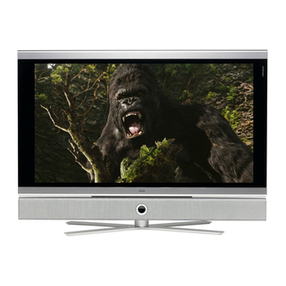
  9. Loewe Articos 55 HD User manual

Loewe Articos 55 HD User manual

Serviceanleitung.
Service Manual. Manuel de Service. Manuale di Servizio.
Instrucciones de servicio. Service-instructies.
Articos 55 HD
Art.-Nr. 63403
Articos 55 HD (US)
Art.-Nr. 63404
230-90422.925
R 2550
RA 2550
Articos 55 HD 63403
Articos 55 HD (US) 63404
1 - 2
1 - 3
Inhaltsverzeichnis
Kapitel 1 Allgemeines
Sicherheitsvorkehrungen.................................................1 - 8
Technische Daten............................................................1 - 11
Technische Daten US......................................................1 - 17
Anschlussplan Loewe Concertos und Articos.................1 - 18
Anschlussplan Loewe Concertos und Articos US...........1 - 19
Anschlussplan Loewe Certos/Concertos und Articos .....1 - 20
Anschlussplan Loewe Certos/Concertos und Articos US...
1 - 21
Verdrahtungsplan Articos ................................................1 - 22
Verdrahtungsplan Articos US..........................................1 - 23
Verdrahtungsplan DVB....................................................1 - 24
Service Menü...................................................................1 - 25
Option Bytes Tabelle .......................................................1 - 26
Kapitel 2 Schaltbilder und Leiterplatten
Schaltbild, Ltpl.
Fernbedienung RC2 .......................................2 - 1 ........2 - 2
Bedienteil ........................................................2 - 3 ........2 - 4
Bedienteil US ..................................................2 - 5 ........2 - 6
DIS Modul .......................................................2 - 7 ........2 - 8
S-Link-Erweiterung .........................................2 - 9 ........2 - 10
HDR Netzteil ...................................................2 - 11 ......2 - 12
Audio Erweiterung ..........................................2 - 13 ......2 - 13
IR-Empfänger .................................................2 - 14 ......2 - 14
Frequenzweiche .............................................2 - 15 ......2 - 15
DVI-Erweiterung .............................................3 - 38 ......2 - 16
Rear Board .....................................................3 - 38 ......2 - 18
Rear Board US ...............................................3 - 38 ......2 - 22
Scaler Board ...................................................3 - 38 ......2 - 26
Dolby Digital AC3 Modul ................................2 - 30 ......2 - 32
Hyperband-Tuner 87271.051 .........................2 - 34 ......2 - 40
Hyperband-Tuner 87345.060 .........................2 - 36 ......2 - 40
Hyperband-Tuner 87507.051 .........................2 - 38 ......2 - 40
Hyperband-Tuner 87346.050 .........................2 - 42 ......2 - 44
Bassverstärker................................................2 - 48 ......2 - 46
Kapitel 3 Ersatzteilelisten
Baugruppenübersicht ......................................................3 - 1
Articos 55 HD...................................................................3 - 2
Articos 55 HD US ............................................................3 - 4
Basic Board .....................................................................3 - 6
Signal Board ....................................................................3 - 8
Signal Board US ..............................................................3 - 13
Optische Bildröhre ...........................................................3 - 17
Vorschaltgerät .................................................................3 - 17
Frequenzweiche ..............................................................3 - 17
Rear Board ......................................................................3 - 18
Rear Board US ................................................................3 - 19
Scaler Board ....................................................................3 - 21
Hyperband-Tuner 87271.051 ..........................................3 - 23
Hyperband-Tuner 87345.060 ..........................................3 - 24
Hyperband-Tuner 87507.051 .........................................3 - 25
Hyperband-Tuner 87346.050 ..........................................3 - 26
DIS Modul ........................................................................3 - 27
Bassverstärker.................................................................3 - 27
Bedienteil .........................................................................3 - 28
Bedienteil US...................................................................3 - 29
DVI-Erweiterung ..............................................................3 - 30
ARS HDR.........................................................................3 - 31
HDR-Netzteil....................................................................3 - 31
HDR-Interface..................................................................3 - 32
Dolby Digital AC3 Modul / Audio Erweiterung ................3 - 33
Fernbedienung RC2 ........................................................3 - 34
LOEWE-Niederlassungen ...............................................3 - 36
Auslandsvertretungen......................................................3 - 37
Anhang
Basic Board (Schaltbild + Leiterpl.).................................3 - 38
Signal Board (Schaltbild + Leiterpl.)................................3 - 38
Scaler Board (Schaltbild).................................................3 - 38
Rear Board (Schaltbild) ...................................................3 - 38
DVI-Erweiterung (Schaltbild)...........................................3 - 38
HDR-Interface (Schaltbild + Leiterpl.) .............................3 - 38
1 - 4
Table of contents
Chapter 1 General
Safety precaution.............................................................1 - 8
Technical specification ....................................................1 - 12
Technical specification US ..............................................1 - 17
Wiring diagram Loewe Concertos & Articos ...................1 - 18
Wiring diagram Loewe Concertos & Articos US .............1 - 19
Wiring diagram Loewe Certos/Concertos & Articos........1 - 20
Wiring diagram Loewe Certos/Concertos & Articos US .1 - 21
Wiring diagram Articos ....................................................1 - 22
Wiring diagram Articos US ..............................................1 - 23
Wiring diagram DVB ........................................................1 - 24
Service menu...................................................................1 - 25
Option Byte Table............................................................1 - 26
Chapter 2 Schematic diagrams and P.C.B. diagrams
Schematic P.C.B.
Remote control RC2 .......................................2 - 1 ........2 - 2
Control unit .....................................................2 - 3 ........2 - 4
Control unit US ..............................................2 - 5 ........2 - 6
DIS Module .....................................................2 - 7 ........2 - 8
S link expansion .............................................2 - 9 ........2 - 10
HDR power supply..........................................2 - 11 ......2 - 12
Audio expansion .............................................2 - 13 ......2 - 13
IR Receiver .....................................................2 - 14 ......2 - 14
Cross-over network ........................................2 - 15 ......2 - 15
DVI extension .................................................3 - 38 ......2 - 16
Rear Board .....................................................3 - 38 ......2 - 18
Rear Board US ...............................................3 - 38 ......2 - 22
Scaler Board ...................................................3 - 38 ......2 - 26
Dolby Digital AC3 Module ..............................2 - 30 ......2 - 32
Hyperband tuner 87271.051...........................2 - 21 ......2 - 27
Hyperband tuner 87345.060...........................2 - 23 ......2 - 27
Hyperband tuner 87507.051...........................2 - 25 ......2 - 27
Hyperband tuner 87346.050...........................2 - 29 ......2 - 31
Subwoofer Amplifier .......................................2 - 23 ......2 - 25
Chapter 3 Spare parts list
Components chart ...........................................................3 - 1
Articos 55 HD...................................................................3 - 2
Articos 55 HD US ............................................................3 - 4
Basic Board .....................................................................3 - 6
Signal Board ....................................................................3 - 8
Signal Board US ..............................................................3 - 13
Optical tube......................................................................3 - 17
Fluorescent lamp ballast .................................................3 - 17
Cross-over network .........................................................3 - 17
Rear Board ......................................................................3 - 18
Rear Board US ................................................................3 - 19
Scaler Board ....................................................................3 - 21
Hyperband tuner 87271.051............................................3 - 23
Hyperband tuner 87345.060............................................3 - 24
Hyperband tuner 87507.051............................................3 - 25
Hyperband tuner 87346.050............................................3 - 26
DIS Module ......................................................................3 - 27
Subwoofer Amplifier ........................................................3 - 27
Control unit ......................................................................3 - 28
Control unit US ................................................................3 - 29
DVI expansion .................................................................3 - 30
ASR HDR.........................................................................3 - 31
HDR Power supply ..........................................................3 - 31
HDR Interface ..................................................................3 - 32
Dolby Digital AC3 Module / Audio expansion .................3 - 33
Remote control RC2 ........................................................3 - 34
LOEWE establishments...................................................3 - 36
Foreign representation ....................................................3 - 37
Appendix
Basic Board (Schematic & P.C.B)...................................3 - 38
Signal Board (Schematic & P.C.B)..................................3 - 38
Scaler Board (Schematic) ...............................................3 - 38
Rear Board (Schematic)..................................................3 - 38
DVI expansion (Schematic).............................................3 - 38
TVO 3 Module (Schematic & P.C.B) ...............................3 - 38
HDR Interface (Schematic & P.C.B) ...............................3 - 38
1 - 5
Table des matières
Chapitre 1 Général
Consignes de sécurité.....................................................1 - 9
Caractéristiques techniques............................................1 - 13
Caractéristiques techniques US......................................1 - 17
Plan de câblage Loewe Concertos et Articos ................1 - 18
Plan de câblage Loewe Concertos et Articos US ..........1 - 19
Plan de câblage Loewe Certos/Concertos et Articos ....1 - 20
Plan de câblage Loewe Certos/Concertos et Articos US ..
1 - 21
Plan de câblage Articos...................................................1 - 22
Plan de câblage Articos US.............................................1 - 23
Plan de câblage DVB ......................................................1 - 24
Menu de service ..............................................................1 - 25
Tableau Option Byte........................................................1 - 26
Chapitre 2 Schematic diagrams and P.C.B. diagrams
Schematic, P.C.B.
Télécommando RC2.......................................2 - 1 ........2 - 2
Bloc de commande.........................................2 - 3 ........2 - 4
Bloc de commande US...................................2 - 5 ........2 - 6
Module DIS .....................................................2 - 7 ........2 - 8
Expansion S Link............................................2 - 9 ........2 - 10
Bloc d’alimentation HDR ................................2 - 11 ......2 - 12
Expansion audio .............................................2 - 13 ......2 - 13
Récepteur IR...................................................3 - 14 ......2 - 14
Aiguille de frequence......................................2 - 15 ......2 - 15
Expansion DVI ................................................3 - 38 ......2 - 16
Rear Board .....................................................3 - 38 ......2 - 18
Rear Board US ...............................................3 - 38 ......2 - 22
Scaler Board ...................................................3 - 38 ......2 -32
Module Dolby Digital AC3 ..............................2 - 30 ......2 - 40
Tuner de hyperbande 87271.051...................2 - 34 ......2 - 40
Tuner de hyperbande 87345.060...................2 - 36 ......2 - 40
Tuner de hyperbande 87507.051...................2 - 38 ......2 - 40
Tuner de hyperbande 87346.050...................2 - 42 ......2 - 44
Amplificateur bassa ........................................2 - 48 ......2 - 46
Chapitre 3 Liste des piéces de rechange
Correspondances des modules ......................................3 - 1
Articos 55 HD...................................................................3 - 2
Articos 55 HD US ............................................................3 - 4
Platine de fondation.........................................................3 - 6
Platine signal ...................................................................3 - 8
Platine signal US .............................................................3 - 13
Optique tube ....................................................................3 - 17
Ballast fluorescente de lampe .........................................3 - 17
Aiguille de frequence.......................................................3 - 17
Rear Board ......................................................................3 - 18
Rear Board US ................................................................3 - 19
Platine scaler ...................................................................3 - 21
Tuner de hyperbande 87271.051....................................3 - 23
Tuner de hyperbande 87345.060....................................3 - 24
Tuner de hyperbande 87507.051....................................3 - 25
Tuner de hyperbande 87346.050....................................3 - 26
Module DIS ......................................................................3 - 27
Amplificateur bassa .........................................................3 - 27
Bloc de commande..........................................................3 - 28
Bloc de commande US....................................................3 - 29
Expansion DVI .................................................................3 - 30
ARS HDR.........................................................................3 - 31
Bloc d’alimentation HDR .................................................3 - 31
Interface HDR ..................................................................3 - 32
Module Dolby Digital AC3 / Expansion audio .................3 - 33
Télécommando RC2........................................................3 - 34
Succursale LOEWE.........................................................3 - 36
Représentation à l’étranger.............................................3 - 37
Appendice
Platinede de fondation (Schéma et Platine) ...................3 - 38
Platine signal (Schéma et Platine) ..................................3 - 38
Platine scaler (Schéma et Platine) ..................................3 - 38
Rear Board (Schéma)......................................................3 - 38
Expansion DVI (Schéma) ................................................3 - 38
Interface HDR (Schéma et Platine).................................3 - 38
1 - 6
Indice
Capitolo 1 Generale
Norme di sicurezza..........................................................1 - 9
Data tecnici ......................................................................1 - 14
Data tecnici US...............................................................1 - 17
Schema Loewe Concertos e Articos ..............................1 - 18
Schema Loewe Concertos e Articos US........................1 - 19
Schema Loewe Certos/Concertos e Articos ..................1 - 20
Schema Loewe Certos/Concertos e Articos US ............1 - 21
Schema connessioni Articos ...........................................1 - 22
Schema connessioni Articos US .....................................1 - 23
Schema connessioni DVB...............................................1 - 24
Menu di servizio...............................................................1 - 25
Tabella byte delle opzioni................................................1 - 26
Capitolo 2 Schéma d’ électrique et plan de comp.
Schéma, Platine
Telecomando RC2..........................................2 - 1 ........2 - 2
Unitá di comando............................................2 - 3 ........2 - 4
Unitá di comando US......................................2 - 3 ........2 - 4
Modulo DIS .....................................................2 - 7 ........2 - 8
Espansione S Link..........................................2 - 9 ........2 - 10
Sezione rete HDR........................................... 2 - 11 ......2 - 12
Espansione audio ...........................................2 - 13 ......2 - 13
Ricevitore IR ...................................................2 - 14 ......2 - 14
Deviatore di frequenze ...................................2 - 15 ......2 - 15
Espansione DVI..............................................3 - 38 ......2 - 16
Rear Board .....................................................3 - 38 ......2 - 18
Rear Board US ...............................................3 - 38 ......2 - 18
Piastra scaler..................................................3 - 38 ......2 - 26
Modulo Dolby Digital AC3 ..............................2 - 30 ......2 - 32
Tuner di iperbanda 87271.051 .......................2 - 34 ......2 - 40
Tuner di iperbanda 87345.060 .......................2 - 36 ......2 - 40
Tuner di iperbanda 87507.051 .......................2 - 38 ......2 - 40
Tuner di iperbanda 87346.050 .......................2 - 42 ......2 - 44
Amplificatore dei bassi ...................................2 - 48 ......2 - 46
Capitolo 3 Lista ricambi
Ordinamento dei gruppi...................................................3 - 1
Articos 55 HD...................................................................3 - 2
Articos 55 HD US ............................................................3 - 4
Piastra di base.................................................................3 - 6
Piastra segnale................................................................3 - 8
Piastra segnale US..........................................................3 - 13
Ottico cinescopio .............................................................3 - 17
Reattanza fluorescente della lamp lampada...................3 - 17
Deviatore di frequenze ....................................................3 - 17
Rear Board ......................................................................3 - 18
Rear Board US ................................................................3 - 19
Piastra scaler...................................................................3 - 12
Tuner di iperbanda 87271.051 ........................................3 - 23
Tuner di iperbanda 87345.060 ........................................3 - 24
Tuner di iperbanda 87507.051 ........................................3 - 25
Tuner di iperbanda 87346.050 ........................................3 - 26
Modulo DIS ......................................................................3 - 27
Amplificatore dei bassi ....................................................3 - 27
Unitá di comando.............................................................3 - 28
Unitá di comando US.......................................................3 - 29
Espansione DVI...............................................................3 - 30
ARS HDR.........................................................................3 - 31
Sezione rete HDR............................................................ 3 - 31
Interface HDR ..................................................................3 - 32
Modulo Dolby Digital AC3 / Espansione audio ...............3 - 33
Telecomando RC2...........................................................3 - 34
Succursale LOEWE.........................................................3 - 36
Rappresentanza all’estero...............................................3 - 37
Appendice
Piastra di base (Schema e Piastra) ................................3 - 38
Piastra segnale (Schema e Piastra) ...............................3 - 38
Piastra scaler (Schema) ..................................................3 - 38
Rear Board (Schema)......................................................3 - 38
Espansione DVI (Schema) ..............................................3 - 38
Interface HDR (Schema e Piastra)..................................3 - 38
1 - 7
Tabla de contenido
Capítulo 1 Generalidades
Normas de seguridad ......................................................1 - 10
Datos técnicos .................................................................1 - 15
Datos técnicos .................................................................1 - 17
Diagrama Loewe Concertos e Spheros .........................1 - 18
Diagrama Loewe Concertos e Spheros US ...................1 - 19
Diagrama Loewe Certos/Concertos e Artikos................1 - 20
Diagrama Loewe Certos/Concertos e Artikos US..........1 - 21
Diagrama de conexiones Artikos ....................................1 - 21
Diagrama de conexiones Artikos US ..............................1 - 22
Diagrama de conexiones DVB ........................................1 - 22
Menú Service...................................................................1 - 25
Tabla de bytes de opciones ............................................1 - 27
Capítulo 2 Esquema de conexiones
y placas de circuito impreso
Esquema Placa
Mando a distancia RC2 ..................................2 - 1 ........2 - 2
Placa del tubo de imagen...............................2 - 3 ........2 - 4
Placa del tubo de imagen US.........................2 - 5 ........2 - 6
Módulo DIS .....................................................2 - 7 ........2 - 8
Expansión S Link............................................2 - 9 ........2 - 10
Equipo de alimentación HDR .........................2 - 11 ......2 - 12
Expansión audio .............................................2 - 13 ......2 - 13
Receptor IR.....................................................2 - 14 ......2 - 14
Diplexor...........................................................2 - 15 ......2 - 15
Expansión DVI ................................................3 - 38 ......2 - 16
Rear Board .....................................................3 - 38 ......2 - 18
Rear Board US ...............................................3 - 38 ......2 - 22
Tarjeta de scaler.............................................3 - 38 ......2 - 26
Módulo Dolby Digital AC3 ..............................2 - 30 ......2 - 32
Sintonizador para hiperbanda 87271.051......2 - 34 ......2 - 40
Sintonizador para hiperbanda 87345.060......2 - 34 ......2 - 40
Sintonizador para hiperbanda 87507.051......2 - 34 ......2 - 40
Sintonizador para hiperbanda 87346.050......2 - 42 ......2 - 44
Amplificador de graves...................................2 - 48 ......2 - 46
Capítulo 3 Lista de piezas de recambio
Vista general de módulos................................................3 - 1
Articos 55 HD...................................................................3 - 2
Articos 55 HD US ............................................................3 - 4
Tarjeta básica ..................................................................3 - 6
Tarjeta de señales ...........................................................3 - 8
Tarjeta de señales US.....................................................3 - 13
Óptico tube de imagen ....................................................3 - 17
Lastre fluorescente de la lámpara...................................3 - 17
Diplexor............................................................................3 - 17
Rear Board ......................................................................3 - 18
Rear Board US ................................................................3 - 19
Tarjeta scaler...................................................................3 - 21
Sintonizador para hiperbanda 87271.051.......................2 - 23
Sintonizador para hiperbanda 87345.060.......................2 - 24
Sintonizador para hiperbanda 87507.051.......................2 - 25
Sintonizador para hiperbanda 87346.050.......................2 - 26
Módulo DIS ......................................................................3 - 27
Amplificatore dei bassi .................................................... 3 - 27
Panel de mando ..............................................................3 - 28
Panel de mando US ........................................................3 - 29
Expansión DVI .................................................................3 - 30
ARS HDR.........................................................................3 - 31
Equipo de alimentación HDR ..........................................3 - 31
Interface HDR ..................................................................3 - 32
Módulo Dolby Digital AC3 / Expansión audio .................3 - 33
Mando a distancia RC2 ...................................................3 - 34
Delegaciones LOEWE.....................................................3 - 36
Delegaciones en el extranjero.........................................3 - 37
Anexo
Tarjeta básica (Esquema de conexiones
y placas de circuito impreso)...........................................3 - 38
Tarjeta de señales (Esquema de conexiones) ...............3 - 38
Tarjeta de scaler (Esquema de conexiones
y placas de circuito impreso)...........................................3 - 38
Rear Board (Esquema de conexiones) ...........................3 - 38
Expansión DVI (Esquema de conexiones) .....................3 - 38
Interface HDR (Esquema de conexiones
y placas de circuito impreso)...........................................3 - 38
1 - 8
Inhoudsopgave
Hoofdstuk 1 Algemeen
Veiligheidsmaatregelen ...................................................1 - 10
Technische gegevens......................................................1 - 16
Technische gegevens US ...............................................1 - 17
Bedradingsschema Loewe Concertos e Artikos .............1 - 18
Bedradingsschema Loewe Concertos e Artikos US .......1 - 19
Bedradingsschema Loewe Certos/Concertos e
Artikos ....1 - 20
Bedradingsschema Loewe Certos/Concertos e
Artikos
US...
1 - 21
Bedradingsschema Artikos..............................................1 - 22
Bedradingsschema Artikos US .......................................1 - 23
Bedradingsschema DVB .................................................1 - 24
Menu Service...................................................................1 - 25
Option Bytes-tabel ...........................................................1 - 26
Hoofdstuk 2 Schakelschema’s en printplaten
Schema’s platen
Afstandsbediening RC2..................................2 - 1 ........2 - 2
Bedieningsgedeelte ........................................2 - 3 ........2 - 4
Bedieningsgedeelte US.................................. 2 - 5 ........2 - 6
DIS moduul .....................................................2 - 7 ........2 - 8
HDR expansie.................................................2 - 9 ........2 - 10
HDR Voedingseenheid ...................................2 - 11 ......2 - 12
Audio expansie ...............................................2 - 13 ......2 - 13
IR Ontvanger ..................................................2 - 14 ......2 - 15
Frequentie flank..............................................2 - 15 ......2 - 15
DVI expansie ..................................................3 - 38 ......2 - 16
Rear Board .....................................................3 - 38 ......2 - 18
Rear Board US ...............................................3 - 38 ......2 - 22
Scaler Board ...................................................3 - 38 ......2 - 26
Dolby Digital AC3 moduul ..............................2 - 30 ......2 - 32
Hyperband-tuner 87271.051 ..........................2 - 34 ......2 - 40
Hyperband-tuner 87345.060 ..........................2 - 36 ......2 - 40
Hyperband-tuner 87507.051 ..........................2 - 38 ......2 - 40
Hyperband-tuner 87346.050 ..........................2 - 42 ......2 - 44
Basversterker..................................................2 - 48 ......2 - 46
Hoofdstuk 3 Onderdelenlijsten
Overzicht van de modules...............................................3 - 1
Articos 55 HD...................................................................3 - 2
Articos 55 HD US ............................................................3 - 4
Basic Board .....................................................................3 - 6
Signal Board ....................................................................3 - 8
Signal Board US ..............................................................3 - 13
Optische Bildröhre ...........................................................3 - 17
Fluorescent lamp ballast .................................................3 - 17
Frequentie flank...............................................................2 - 17
Rear Board ......................................................................3 - 18
Rear Board US ................................................................3 - 19
Scaler Board ....................................................................3 - 21
Hyperband-tuner 87271.051 ...........................................2 - 23
Hyperband-tuner 87345.060 ...........................................2 - 24
Hyperband-tuner 87507.051 ...........................................2 - 25
Hyperband-tuner 87346.050 ...........................................2 - 26
DIS moduul ......................................................................3 - 27
Basversterker...................................................................3 - 27
Bedieningsgedeelte .........................................................3 - 28
Bedieningsgedeelte US...................................................3 - 29
DVI expansie ...................................................................3 - 30
ARS HDR.........................................................................3 - 31
HDR Voedingseenheid ....................................................3 - 31
HDR Interface ..................................................................3 - 32
Dolby Digital AC3 moduul / Audio expansie ..................3 - 33
Afstandsbediening RC2...................................................3 - 34
LOEWE-vestigingen ........................................................3 - 36
Vertegenwoordigingen in het buitenland.........................3 - 38
Appendix
Basic Board (schakelschema + printplaat) .....................3 - 38
Signal Board (schakelschema + printplaat) ....................3 - 38
Scaler Board (schakelschema) ....................................... 3 - 38
Rear Board(schakelschema)...........................................3 - 38
DVI expansie (schakelschema + printplaat) ...................3 - 38
HDR Interface (schakelschema + printplaat) ..................3 - 34
1 - 9
Hinweis zum Schutz gegen Elektrostatik
1. Elektrostatisch gesicherte MOS-Arbeitsplätze.
Der Umgang mit gegen Elektrostatik empfindlichen Bauteilen muß
an einem elektrostatisch gesicherten MOS-Arbeitsplatz erfolgen.
Ein elektrostatisch gesicherter MOS-Arbeitsplatz erdet über
Entladungswiderständesämtliche leitende Materialien einschließlich
der Person. Nichtleiter werden durch Luftionisation entladen. Die
Integration von Lötkolben und Meßgeräten in den gesicherten MOS-
Arbeitsplatz ist nur mit Trenntrafo in jedem der verwendeten Geräte
möglich. Die Meßgeräte-Massen werden ebenfalls mit Entladungs-
widerständen geerdet.
2. Gesicherte Verpackung durch leitfähige Materialien.
ZumSchutzgegenElektrostatik werden elektrisch leitendeKunststoffe
für Verpackung und Transportmittel verwendet. Leitende Kunststoffe
gibt es als schwarze oder transparente Schutzbeutel, Schaumstoff,
Folien und als Behälter.
Empfindliche Bauteile dürfen nur am gesicherten MOS-Arbeits-platz
aus der Verpackung entfernt bzw. verpackt werden.
Sicherheitshinweise/Vorschriften
1. Instandsetzungen, Änderungen und Prüfung netzbetriebener
elektronischer Geräte und deren Zubehör dürfen nur von
fachkundigen Personen ausgeführt werden.
2. Es gelten die Vorschriften und Sicherheitshinweise nach VDE 0701,
Teil200, und die Vorschriftenund Sicherheitshinweisedes jeweiligen
Landes!
3. VDE 0701, Teil 200, beinhaltet Vorschriften zur Instandsetzung,
Änderung und Prüfung netzbetriebener elektronischer Geräte und
deren Zubehör.
4. Vor der Auslieferung des Geräts muß eine Sichtprüfung des Geräts
undderAnschlußleitungen(undsoweitvorhanden,desSchutzleiters),
und die Messung des Isolationswiderstandes und des Ersatz-
Ableitstromes nach VDE 0701, Teil 200, durchgeführt werden. Der
niederohmige Durchgang des Schutzleiters ist durch Messung laut
Vorschrift VDE 0701, Teil 1, nachzuweisen.
5. Die Vorschriften des jeweiligen Landes sind zusätzlich zu beachten.
6. Bauteile mit dem Symbol gekennzeichnet, dürfen nur durch
Originalteile ersetzt werden.
Hinweis:
Serviceunterstützung, siehe Servicekoffer 90417.922
CAUTION:
These servicing instructions are for use by qualified service personal
only. To reduce the risk of electric shock do not perform any servicing
other then that contained in the operating instructions unless you are
qualified to do so:
Note on electrostatic shielding
1. Electrostatically shielded MOS workstations
Components sensitive to electrostatic discharge must be handled at
workstation with electrostatic shielding. An electrostatically shielded
MOS workstation is fitted with discharge resistor which earth all
conductive materials, including the technician working there.
Dielectricsaredischarged by air ionisation.The use of soldering irons
and measuring equipment at shielded workstation is only possible in
conjunction with isolating transformer in each of the devices used.
Measuring equipment chassis are also earthed with discharge
resistors.
2. Shielded packaging using conductive materials
To protectagainstelectrostaticcharges,electrically conductive plastics
are used for packaging and transport purposes. Conductive plastics
are available in the form of transparent protective bags, foam plastic,
film sheeting or containers. Sensitive components requiring the use
ofprotectivepackagingmust only be packedandunpackedatshielded
workstations
Safety warnings/regulations
1. The repair, modification and testing of mains-operated electronic
devices and their accessories must only be performed by qualified
persons.
2. It is necessary to follow the regulations and safety warnings to VDE
0701, part 200, as well as the regulations and safety warnings
applicable in the country concerned.
3. VDE 0701, Part 2, contains regulations on the repair, modification
and testing of mains-operated electronic devices and their
accessories.
4. Before delivery, the device and the connecting leads (including any
protectiveearthconductor fitted) must undergo visual inspection,and
the insulation resistance and the equivalent leakage current must be
measured according to VDE 0701, part 200. The low-resistance
continuity of the protective earth conductor must be verified by
measurement to VDE regulation 0701, part 1.
5. The regulations of the country concerned must also be observed.
6. Only genuine parts must be used for replacing components marked
with the symbol
Note:
Service support, see service suitcase 90417.922
1 - 10
Nota per la protezione da scariche elettro-
statiche
1. Posti di lavoro MOS protetti elettrostaticamente
Lamanipolazionedi componenti sensibili alle scariche elettrostatiche
deve essere eseguita a posti di lavoro MOS protetti da queste
scariche. Un posto di lavoro MOS protetto dalle scariche
elettrostatiche convoglia a terra tutti i materiali conduttori compresa
la persona mediante resistenze di scarica. Gli isolatori vengono
scaricati mediante ionizzazione dell’aria. L’integrazione di saldatoi e
apparecchi di misura nel posto di lavoro MOS protetto é possibile
soloattraversotrasformatoridiseparazionein ogni apparecchio usato.
Anchele massa degli apparecchi dimisuravengono scaricate a terra
mediante resistente di scarica.
2. Imballaggio protetto mediante materiali conduttori
Per proteggere le componenti dalle scariche elettrostatiche vengono
usati degli imballaggi e dei mezzi di trasporto di materiale sintetico
conduttore. Esistono imballaggi di materiale sintetico conduttore
sottoforma di sacchetti di protezione trasparenti o neri, materiale
schiumoso, fogli e contenitori.
Componentisensibili devono essere tolti, risp.messi negli imballaggi
di materiale conduttore solo in un posto di lavoro MOS protetto.
Note per la sicurezza/disposizioni
1. Riparazioni, modifiche e controlli su apparecchiature elettroniche
ed accessori collegati alla rete elettrica devono essere eseguiti
esclusivamente da personale esperto.
2. Si applicano le disposizioni e le note per la sicurezza della norma
VDE 0701, parte 200, e quelle del Paese di installazione.
3. VDE 0701, parte 200, riporta le disposizioni per le riparazioni,
modifiche e controlli su apparecchiature elettroniche ed accessori
collegati alla rete elettrica.
4. Prima della consegna, si deve effettuare un controllo visivo
dell’apparecchio e dei cavi di collegamento (anche del conduttore
di protezione, se presente) nonchè la misurazione della resistenza
di isolamento e della corrente deviata sostitutiva secondo la norma
VDE 0701, parte 200. La continuità a basso valore ohmico del
conduttoredi protezione va dimostratasecondo la norma VDE 0701,
parte 1.
5. Sidevonorispettare anche le disposizioni relative invigorenelPaese
di installazione.
6. Componenti contrassegnati con il simbolo devono essere
sostituiti solo con ricambi originali.
Nota:
Appoggio servizio, vedere valigia servizio 90417.922
Recommandations pour la protection con
tre les charges électrostatiques
1. Postes de travail MOS protégés électrostatiquement
La manipulation de composants sensibles aux charges
électrostatiques doit impérativement se faire a un poste de travail
MOS protégé électrostatiquement. Un tel poste de travail MOS
protégé électrostatiquement met tous les matéraux conducteurs à la
masse par l’intermédiaire de résistances de décharge, y compris la
personne qui y travaille. Les nonconducteurs sont déchargés par
ionisation de l’air. L’intégration de fers 3 souder et d’appareils de
mesure dans le poste de travail MOS protégé électrostatiquement
n’est admissible que par l’intermédiaire de transformateurs de
séparation intégrés à chacun des appareils. Les terres des appareils
de mesure sont également mises 3 la masse par l’intermédiaire de
résistance de décharge.
2. Emballages de sécurité faits de matériaux conducteurs
Poulesprotégercontreleschargesélectrostatiques,lescom-posants
sensiblessont emballes et transportes dansdes matièresplastiques
conductrices d’électricité. Les matières plastiques conductrises
existent en tant que sachets de protection noirs ou transparents,
mousses, feuilles et aussi en tant que conteneurs. Les composants
sensibles ne doivent être sortis de leu emballage conducteur ou y
êtreemballesqu’auposte de travail MOSélectrostatiquementprotégé.
Consignes et prescriptions de sécurité
1. Les remises en état, modifications et examen d’appareils électroni-
ques exploités sur réseau, et leurs accessoires, ne doivent être
exécutés que par des professionnels.
2. On appliquera les prescriptions et consignes de sécurité selon VDE
0701, partie 200, et les prescriptions et consignes de sécurité du
pays respectif!
3. VDE 0701, partie 200, comporte des prescriptions sur la remise en
état, modification et examen d’appareils électroniques exploités sur
réseau, et leurs accessoires.
4. Avant la livraison de l’appareil, il faut effectuer un examen visuel de
l’appareil et câbles de branchement (et si existant de la terre), et la
mesure de la résistance d’isolation et du courant de fuite de
remplacement selon VDE 0701, partie 200. Le passage de basse
impédance de la terre doit être démontré par une mesure
conformément à la prescription VDE 0701, partie 1.
5. Les prescriptions du pays respectif doivent être également
observées.
6. Les éléments caractérisés avec le symbole ne doivent être
remplacés que par des pièces originales.
Consigne:
Aide service, voir valise service 90417.922
1 - 11
Advertencia para la protección contra
cargas electrostáticas
1. Protección contra cargas electrostáticas en puestos de
manipulación de módulos MOS
La manipulación de piezas sensibles contra cargas electrostáticas
debe realizarse en puestos de manipulación de módulos MOS
protegidos contra dichas cargas.
Paraqueunpuestodemanipulacióndemódulos MOS esté protegido
contra descargas electrostáticas, todos los materiales conductores,
incluído el operario, deben conectarse a tierra mediante resistencias
de descarga. Los elementos no conductores deben descargarse
mediante un ionizador de aire. La integración de soldadores y
aparatos de medición en los puestos de manipulación de módulos
MOS sólo se puede realizar con transformadores separadores en
cadaaparato utilizado.Tambiéndeben conectarse a tierralasmasas
de los aparatos de medición utilizando resistencias de descarga.
2. Embalaje protegido con materiales conductores
Para la protección contra las cargas electrostáticas se utilizan
materiales sintéticos conductores para el embalaje y el transporte.
Los materiales sintéticos conductores están disponibles en forma de
bolsas protectoras negras o transparentes, gomaespuma, películas
y envases.
Las piezas electrostáticamente sensibles deben embalarse y/o
desembalarse solamente en puestos de manipulación de módulos
MOS.
Advertencias y normas de seguridad
1. Las puestas a punto, cambios y revisiones de aparatos electrónicos
alimentados por la red y sus accesorios, sólo deben realizarse por
personas especializadas.
2. Son aplicables las advertencias y normas de seguridad detalladas
en la norma VDE 0701, apartado 200 y las correspondientes de
cada país.
3. Elapartado 200 de la normaVDE0701 describe las puestas apunto,
cambios y revisiones de aparatos electrónicos alimentados por la
red y sus accesorios.
4. Antes de efectuar el suministro del aparato debe realizarse una
comprobación visual del mismo y de las líneas de conexión (y, en su
caso,dela línea protectora), así comounamedición de la resistencia
de aislamiento y de la corriente sustitutiva de escape según VDE
0701, apartado 200. Debe verificarse la baja resistencia de la línea
protectora recogida en la norma VDE 0701, apartado 1.
5. Se han de tener en cuenta además las normas de los países
correspondientes.
6. Las piezas marcadas con el símbolo sólo podrán reemplazarse
por piezas originales.
Nota:
Apoyo servicio, ver maleta servicio 90417.922
Aanwijzing ter bescherming tegen
elektrostatica
1. Elektrostatisch beveiligde MOS-werkplekken.
De omgang met voor elektrostatica gevoelige componenten moet op
een elektrostatisch beveiligde MOS-werkplek plaatsvinden.
Bij een elektrostatisch beveiligde MOS-werkplek worden alle
geleidendematerialenen de persoon zelf viaontladingsweerstanden
geaard. Niet-geleiders worden door luchtionisatie ontladen. De
integratievansoldeerboutenenmeetapparatenin de beveiligde MOS-
werkplek is alleen met een scheidingstransformator in elk van de
gebruikte apparaten mogelijk. De massa’s van de meetapparaten
worden eveneens met ontladingsweerstanden geaard.
2. Veilige verpakking door geleidende materialen.
Ter bescherming tegen elektrostatica worden elektrisch geleidende
kunststoffen voor de verpakking en de transportmiddelen gebruikt.
Geleidende kunststoffen zijn als zwarte of transparante
beschermzakjes, schuimstof, folie en als container verkrijgbaar.
Gevoelige componenten mogen alleen op de beveiligde MOS-
werkplek uit de verpakking worden gehaald resp.worden verpakt.
Veiligheidsinstructies/voorschriften
1. Elektronische apparaten met netvoeding en hun toebehoren mogen
uitsluitenddoorvakkundigepersonen worden gerepareerd, gewijzigd
en gecontroleerd.
2. De voorschriften en veiligheidsinstructies volgens VDE 0701, deel
200, en de voorschriften en veiligheidsinstructies van het
desbetreffende land zijn van kracht!
3. VDE 0701, deel 200, bevat de voorschriften voor de reparatie, de
wijzigingen de controle vanelektronische apparaten met netvoeding
en hun toebehoren.
4. Voordat het toestel wordt afgeleverd, moeten het toestel en de
aansluitleidingen (en voor zover aanwezig, de aarddraad) aan een
visuele controle worden onderworpen en de isolatieweerstand en de
reserve-lekstroom conform VDE 0701, deel 200, worden gemeten.
Delaagohmigedoorgangvandeaarddraadmoet door meting volgens
voorschrift VDE 0701, deel 1, worden aangetoond.
5.Tevensdienen de voorschriften van hetdesbetreffendeland in acht te
worden genomen.
6. Componenten die gekenmerkt zijn met het symbool , mogen
uitsluitend door originele reserveonderdelen worden vervangen.
Aanwijzing:
Service ondersteuning, zien service koffer 90417.922
1 - 12
Technische Daten
Mechanische Daten
Articos 55 HD Artikelnummer 63403
Abmessungen (cm) 136,9 x 103,5 x 52 (B x H x T)
Masse (kg) 76,5
Technologie 1-Panel DLP Optical System
made by Carl Zeiss
Bild-Format 16 : 9
Bilddiagonale sichtbar 140 cm
Pixel-Format 1280 x 720 progressiv
Relative Luftfeuchte 20 ... 80%
keine Kondensation
Luftdruck 800 ... 1114 HPa (0 ... 3000 m NN)
Elektrische Daten
Chassisbezeichnung R 2550
Digital Light Processing™ Technology
Projektionslampe 120 Watt long life
Stromversorgung 120 V bis 240 V / 50-60Hz
Leistungsaufnahme 190 Watt
Standby < 3 Watt
Umgebungstemperatur 0º – 40º Celsius
Full Digital AMD / DNC einstellbar
Tuner VHF/UHF/ Kabel
(Hyperband 8 MHz) 42 MHz bis 860 MHz
Programmplatzspeicher 220
mit DVB-Decoder 1470
TV-Normen PAL-B/G, PAL-D/K,
PAL-I, PAL-L
PAL M/N, PAL 60
Secam B/G, D/K, L
NTSC / NTSCV
Teletext Hi-Text (Level 2.5)
Ton-Normen Mono/Stereo/2-Ton
Nicam B/G, L, I
Audio-Nennleistung 2 x 20 Watt / 4 Ohm
Audio-Musikleistung 2 x 40 Watt / 4 Ohm
Lautsprecher 2 geschlossene Boxen
Hochtöner Ø 50 mm Kalotte
Tieftöner Ø 104 mm
Anschlüsse (linke Gehäuseseite)
Mini-DIN S-Video-Eingang (AVS) SVHS / Hi 8 /
VHS / 8 mm
Cinch Video-Eingang (AVS) VHS / 8 mm
Cinch Toneingänge L + R
Kopfhöreranschluss Klinke 6,3mm 32 – 200 Ohm
Anschlüsse (Rückseite)
IEC-Buchse 75 Ohm Antenne / Kabel/PIP
EURO-AV 1: Video IN SVHS / Hi 8 /
VHS / 8 mm
Video OUT SVHS / Hi 8 /
VHS / 8 mm
Audio IN/OUT L + R
EURO-AV 2: Video IN SVHS / Hi 8 / RGB /
VHS / 8 mm
Video OUT (SVHS / Hi 8
nur bei SVHS Link Plus)
VHS / 8 mm
Audio IN/OUT L + R
EURO-AV 3: Video IN/OUT SVHS / Hi 8 / RGB /
YUV / VHS / 8 mm
Audio IN L + R
Component IN:
Cinch Y-Signal
Cinch Cr/Pr-Signal
Cinch Cb/Pb-Signal
2xCinch L+R AUDIO OUT
2xCinch L+R AUDIO IN 1
Klinkenbuchse 3,5mm AUDIO IN 2
2xCinch L+R AUDIO IN 3
Cinch-Eingangsbuchse IN 1 Digital-Ton
Cinch-Eingangsbuchse IN 2 Digital-Ton
Cinch-Ausgangsbuchse OUT Digital-Ton
SYSTEM-Buchse, 9-polig AUDIO
Infrarot-Link Klinkenbuchse 3,5 mm
RC5/RC6 Klinkenbuchse 2,5 mm
Service-Buchse 8-polig
Anschluss DVI Digital-Eingang
Eingang-VGA über DVI-Buchse mit
optionalem Adapter
Buchse CTRL für Drehfuß-Steuerung
1 - 13
Technical data
Mechanical data
Articos 55 HD article number 63403
Dimensions (cm) 136.9 x 103.5 x 52 (W x H x D)
Weight (kg) 76.5
Technology 1-Panel DLP Optical System
made by Carl Zeiss
Picture format 16 : 9
Visible screen diagonal 140 cm
Pixel format 1280 x 720 progressive
Relative humidity 20 ... 80%
No condensation
Air pressure 800 ... 1114 HPa (0 ... 3000 m
above sea level)
Electrical data
Chassis designation R 2550
Digital Light Processing™ Technology
Projection lamp 120 Watt long life
Power supply 120 V to 240 V / 50-60Hz
Power consumption 190 Watt
Standby < 3 Watt
Ambient temperature 0º - 40º Celsius
Full Digital AMD / DNC adjustable
Tuner VHF/UHF/ cable
(Hyperband 8 MHz) 42 MHz to 860 MHz
Station memory 220
with DVB decoder 1470
TV standards PAL-B/G, PAL-D/K,
PAL-I, PAL-L
PAL M/N, PAL 60
Secam B/G, D/K, L
NTSC / NTSCV
Teletext Hi-Text (Level 2.5)
Audio standards mono/stereo/2-sound
Nicam B/G, L, I
Audio rated output 2 x 20 Watt / 4 Ohm
Audio music output 2 x 40 Watt / 4 Ohm
2 enclosed speakers
Treble Ø 50 mm cone
Bass Ø 104 mm
Terminals (left side of housing)
Mini-DIN S-Video-In (AVS) SVHS / Hi 8 /
VHS / 8 mm
Cinch Video-In (AVS) VHS / 8 mm
Cinch Audio In L + R
Headphones jack 6.3mm 32 - 200 Ohm
Terminals (rear)
IEC socket 75 Ohm antenna / cable/PIP
EURO-AV 1: Video IN SVHS / Hi 8 /
VHS / 8 mm
Video OUT SVHS / Hi 8 /
VHS / 8 mm
Audio IN/OUT L + R
EURO-AV 2: Video IN SVHS / Hi 8 / RGB /
VHS / 8 mm
Video OUT (SVHS / Hi 8
only on SVHS Link Plus)
VHS / 8 mm
Audio IN/OUT L + R
EURO-AV 3: Video IN/OUT SVHS / Hi 8 / RGB/
YUV / VHS / 8 mm
Audio IN L + R
Component IN:
Cinch Y-signal
Cinch Cr/Pr-signal
Cinch Cb/Pb-signal
2xCinch L+R AUDIO OUT
2xCinch L+R AUDIO IN 1
Jack 3.5mm AUDIO IN 2
2xCinch L+R AUDIO IN 3
Cinch input socket IN 1 Digital-Audio
Cinch-input socket IN 2 Digital-Audio
Cinch-output socket OUT Digital-Audio
SYSTEM socket, 9-pin AUDIO
Infrared link jack 3.5 mm
RC5/RC6 jack 2.5 mm
Service socket 8-pin
Connection DVI Digital-Input
Input-VGA via DVI-socket with
Optional adapter
Socket CTRL for rotary stand control
1 - 14
Caractéristiques mécaniques
Articos 55 HD Numéro d’article 63403
Dimensions (cm) 136,9 x 103,5 x 52 (L x H x P)
Poids (kg) 76,5
Technologie 1-Panel DLP Syst me optique
made by Carl Zeiss
Format d’image 16:9
Diagonale d’image visible 140 cm
Format pixel 1280 x 720 progressif
Humidit relative de l’air 20 ... 80%
aucune condensation
Pression 800 ... 1114 HPa (0 ... 3000 m NN)
Caractéristiques électriques
Désignation du châssis R 2550
Digital Light Processing™ Technology
Lampe de projection 120 Watt longue durée
Alimentation 120 V à 240 V / 50-60Hz
Puissance consomm e 190 Watt
Veille < 3 Watt
Temp rature ambiante 0º - 40º Celsius
Full Digital AMD / DNC réglable
Tuner VHF/UHF/ Câble
(Hyperband 8 MHz) 42 MHz à 860 MHz
Mmoire de programmes 220
avec d codeur DVB 1470
Normes TV PAL-B/G, PAL-D/K,
PAL-I, PAL-L
PAL M/N, PAL 60
Secam B/G, D/K, L
NTSC / NTSCV
Télétexte Hi-Text (niveau 2.5)
Normes son mono/stéréo/dual
Nicam B/G, L, I
Puissance nominale audio 2 x 20 Watt / 4 Ohm
Puissance musicale audio 2 x 40 Watt / 4 Ohm
Haut-parleurs 2 enceintes ferm es
Aiguës Ø 50 mm calotte
Graves Ø 104 mm
Connexions (côté gauche du coffret)
Entrée S-vidéo mini-DIN (AVS) SVHS / Hi 8 /
VHS / 8 mm
Cinch entr e vid o (AVS) VHS / 8 mm
Cinch entrée son L + R
Prise casque Jack 6,3mm 32 - 200 Ohm
Connexions (dos du téléviseur)
Prise IEC 75 Ohm Antenne /Câble/PIP
EURO-AV 1 : Vidéo IN SVHS / Hi 8 /
VHS / 8 mm
Vidéo OUT SVHS / Hi 8 /
VHS / 8 mm
Audio IN/OUT L + R
Caractéristiques techniques
EURO-AV 2 : Vidéo IN SVHS / Hi 8 / RGB /
VHS / 8 mm
Vidéo OUT (SVHS / Hi 8
uniquement pour SVHS Link Plus)
VHS / 8 mm
Audio IN/OUT L + R
EURO-AV 3 : Vidéo IN/OUT SVHS / Hi 8 / RGB /
YUV / VHS / 8 mm
Audio IN L + R
Component IN :
Cinch Signal Y
Cinch Signal Cr/Pr
Cinch Signal Cb/Pb
2xcinch L+R AUDIO OUT
2xcinch L+R AUDIO IN 1
Cinch 3,5mm AUDIO IN 2
2xcinch L+R IN 3
Cinch entr e IN 1 son num rique
Cinch entr e IN 2 son num rique
Cinch entr e OUT son num rique
Prise SYSTÈME, 9 pôles AUDIO
Douille de jack infrarouge 3,5 mm
Douille de jack RC5/RC6 2,5 mm
Prise Service 8 pôles
Prise DVI entrée numérique
Entrée VGA via prise DVI avec
adaptateur optionnel
Prise CTRL pour la commande du pied rotatif
1 - 15
Dati tecnici
Dati meccanici
Articos 55 HD codice articolo 63403
Dimensioni (cm) 136,9 x 103,5 x 52 (largh. x alt. x prof.)
Massa (kg) 76,5
Tecnologia 1-Panel DLP Optical System
made by Carl Zeiss
Formato immagine 16 : 9
Diagonale immagine visibile 140 cm
Formato Pixel 1280 x 720 progressivo
Umiditˆ relativa dell’aria 20 ... 80%
No condensa
Pressione dell’aria 800 ... 1114 HPa (0 ... 3000 m NN)
Dati elettrici
Denominazione chassis R 2550
Digital Light Processing™ Technology
Lampada proiezione 120 Watt long life
Alimentazione elettrica 120 V - 240 V / 50-60Hz
Potenza assorbita 190 Watt
Standby < 3 Watt
Temperatura ambiente 0º - 40º Celsius
Full Digital AMD / DNC impostabile
Sintonizzatore VHF/UHF/ cavo
(iperbanda 8 MHz) 42 MHz - 860 MHz
Quantità programmi 220
con decodificatore DVB 1470
Norme TV PAL-B/G, PAL-D/K,
PAL-I, PAL-L
PAL M/N, PAL 60
Secam B/G, D/K, L
NTSC / NTSCV
Televideo Hi-Text (livello 2.5)
Norme audio Mono/Stereo/2 modalità audio
Nicam B/G, L, I
Potenza nominale audio 2 x 20 Watt / 4 Ohm
Potenza musica audio 2 x 40 Watt / 4 Ohm
Altoparlanti 2 box chiusi
Alti Ø 50 mm calotta
Bassi Ø 104 mm
Collegamenti (parte sinistra della scatola)
Ingresso Mini-DIN S-Video (AVS) SVHS / Hi 8 /
VHS / 8 mm
Ingresso Cinch Video (AVS) VHS / 8 mm
Ingressi Cinch audio L + R
Collegamento cuffia Jack 6,3mm 32 - 200 Ohm
Collegamenti (retro)
Presa IEC 75 Ohm Antenna / cavo/PIP
EURO-AV 1: Video IN SVHS / Hi 8 /
VHS / 8 mm
Video OUT SVHS / Hi 8 /
VHS / 8 mm
Audio IN/OUT L + R
EURO-AV 2: Video IN SVHS / Hi 8 / RGB /
VHS / 8 mm
Video OUT (SVHS / Hi 8
Solo per SVHS Link Plus)
VHS / 8 mm
Audio IN/OUT L + R
EURO-AV 3: Video IN/OUT S-VHS / Hi 8 / RGB /
YUV / VHS / 8 mm
Audio IN L + R
Component IN:
Cinch Y-Signal
Cinch Cr/Pr-Signal
Cinch Cb/Pb-Signal
2xCinch L+R AUDIO OUT
2xCinch L+R AUDIO IN 1
Presa jack 3,5mm AUDIO IN 2
2xCinch L+R AUDIO IN 3
Presa ingresso Cinch IN 1 Audio digitale
Presa ingresso Cinch IN 2 Audio digitale
Presa uscita Cinch OUT Audio digitale
Presa SYSTEM, 9 poli AUDIO
Presa jack link infrarossi 3,5 mm
Presa jack RC5/RC6 2,5 mm
Presa di servizio a 8 poli
Collegamento DVI ingresso digitale
Ingresso VGA tramite presa DVI con
adattatore opzionale
Presa CTRL per comando sostegno rotante
1 - 16
Datos técnicos
Datos mecánicos
Articos 55 HD nœmero de referencia 63403
Dimensiones (cm) 136,9 x 103,5 x 52 (A xA x P)
Peso (kg) 76,5
Tecnología 1-Panel DLP Optical System
made by Carl Zeiss
Formato de imagen 16 : 9
Diagonal visible de imagen 140 cm
Formato pixel 1280 x 720 progresivo
Humedad relativa del aire 20 ... 80%
sin condensación
Presión del aire 800 ... 1114 HPa (0 ... 3000 m NN)
Datos eléctricos
Denominación de chasis R 2550
Digital Light Processing™ Technology
Lámpara de proyección de 120 vatios de larga duración
Suministro de corriente desde 120 V hasta 240 V / 50-60Hz
Consumo de potencia 190 vatios
Modo de espera (Standby) < 3 vatios
Temperatura ambiente 0º - 40º Celsius
Full Digital AMD / DNC ajustable
Sintonizador VHF/UHF/ Cable
(Hiperbanda 8 MHz) desde 42 MHz hasta 860 MHz
Memoria de volumen de programas 220
con descodificador DVB 1470
Normas de TV PAL-B/G, PAL-D/K,
PAL-I, PAL-L
PAL M/N, PAL 60
Secam B/G, D/K, L
NTSC / NTSCV
Teletexto Hi-Text (nivel 2.5)
Normas de sonido mono/est reo/2-Ton
Nicam B/G, L, I
Potencia acústica nominal 2 x 20 vatios / 4 Ohm
Potencia acústica musical 2 x 40 vatios / 4 Ohm
Altavoces 2 unidades conectadas
Sonidos agudos Ø 50 mm cœpula
Sonidos graves Ø 104 mm
Conexiones (lado izquierdo de la carcasa)
Entrada de vídeo S Mini-DIN (AVS) SVHS / Hi 8 /
VHS / 8 mm
Entrada de vídeo Cinch (AVS) VHS / 8 mm
Entradas de sonido Cinch L + R
Conexión de auriculares
Clavija 6,3 mm 32 - 200 Ohm
Conexiones (parte posterior)
Hembrilla IEC 75 Ohm antena / cable/PIP
EURO-AV 1: Vídeo IN SVHS / Hi 8 /
VHS / 8 mm
Vídeo OUT SVHS / Hi 8 /
VHS / 8 mm
Audio IN/OUT L + R
EURO-AV 2: Vídeo IN SVHS / Hi 8 / RGB /
VHS / 8 mm
Vídeo OUT (SVHS / Hi 8
sólo para SVHS Link Plus)
VHS / 8 mm
Audio IN/OUT L + R
EURO-AV 3: Vídeo IN/OUT SVHS / Hi 8 / RGB /
YUV / VHS / 8 mm
Audio IN L + R
Componentes IN:
Señal Cinch Y
Señal Cinch Cr/Pr
Señal Cinch Cb/Pb
2xCinch L+R AUDIO OUT
2xCinch L+R AUDIO IN 1
Conector de clavijas 3,5 mm AUDIO IN 2
2xCinch L+R AUDIO IN 3
Conector de entrada Cinch IN 1 Digital
Conector de entrada Cinch IN 2 Digital
Conector de salida Cinch OUT Digital
Conector SYSTEM, 9 polos AUDIO
Conector de clavijas de conexión infraroja 3,5 mm
RC5/RC6 conector de clavijas 2,5 mm
Conector Service 8 polos
Conexión DVI entrada digital
Entrada VGA a trav s del conector DVI con
adaptador opcional
Conector CTRL para el control del pie giratorio
1 - 17
Technische gegevens
Mechanische gegevens
Articos 55 HD artikelnummer 63403
Afmetingen (cm) 136,9 x 103,5 x 52 (b x h x d)
Gewicht (kg) 76,5
Technologie 1-Panel DLP Optical System
Made by Carl Zeiss
Beeldformaat 16 : 9
Beelddiagonaal zichtbaar 140 cm
Pixelformaat 1280 x 720 progressief
Relatieve luchtvochtigheid 20...80%
Geen condensatie
Luchtdruk 800...1114 HPa (0...3000 m NN)
Elektrische gegevens
Chassisbenaming R 2550
Digital Light Processing™ Technology
Projectielamp 120 watt long life
Stroomvoorziening 120 V tot 240 V / 50-60 Hz
Krachtontneming 190 watt
Stand-by < 3 watt
Omgevingstemperatuur 0°- 40°Celsius
Full Digital AMD / DNC instelbaar
Tuner VHF/UHF kabel
(Hyperband 8 MHz) 42 MHz tot 860 MHz
Programmageheugen 220
met DVB-Decoder 1470
TV-normen PAL-B/G, PAL-D/K,
PAL-I, PAL-L
PAL M/N, PAL 60
Secam B/G, D/K, L
NTSC / NTSCV
Teletekst Hi-tekst (Level 2.5)
Klanknormen mono/stereo/2-Ton
Nicam B/G, L, I
Nominaal vermogen audio 2 x 20 watt / 4 ohm
Muzikaal vermogen audio 2 x 40 watt / 4 ohm
Luidsprekers 2 gesloten boxen
Hoge tonen Ø 50 mm sferische kap
Lage tonen Ø 104 mm
Aansluitingen (linkerzijde behuizing)
Mini-DIN S-video-ingang (AVS) SVHS / Hi 8 /
VHS / 8 mm
Cinch video-ingang (AVS) VHS / 8 mm
Cinch klankingangen L + R
Aansluiting hoofdtelefoon Stekker 6,3mm 32 - 200 ohm
Aansluitingen (achterzijde)
IEC-bus 75 ohm antenne / kabel/PIP
EURO-AV 1: Video IN SVHS / Hi 8 /
VHS / 8 mm
Video OUT SVHS / Hi 8 /
VHS / 8 mm
Audio IN/OUT L + R
EURO-AV 2: Video IN SVHS / Hi 8 / RGB /
VHS / 8 mm
Video OUT (SVHS / Hi 8
uitsluitend bij SVHS Link Plus)
VHS / 8 mm
Audio IN/OUT L + R
EURO-AV 3: Video IN/OUT S-VHS / Hi 8 / RGB /
YUV / VHS / 8 mm
Audio IN L + R
Component IN:
Cinch Y-signaal
Cinch Cr/Pr-signaal
Cinch Cb/Pb-signaal
2xCinch L+R AUDIO OUT
2xCinch L+R A UDIO IN 1
Stekkerbus 3,5mm UDIO IN 2
2xCinch L+R AUDIO IN 3
Cinch-ingangsbus IN 1 digitale klank
Cinch-ingangsbus IN 2 digitale klank
Cinch-uitgangsbus OUT digitale klank
SYSTEM-bus, 9-polig AUDIO
Infrarood-Link stekkerbus 3,5 mm
RC5/RC6 stekkerbus 2,5 mm
Servicebus 8-polig
Aansluiting DVI digitale ingang
Ingang-VGA via DVI-bus met
optionele adapter
Bus CTRL voor draaivoetbesturing
1 - 18
Technical Specification
Physical Data
Articos 55 HD (US) Article no. 63404
Technology 1-Panel DLP Rear Projection
Colors Basalt (highgloss, matt), Platinum
Shipping Weight lbs 284.5
Weight (lbs.) 182
Dimensions (WxHxD) 54” x 41” x 19.5”
Display
Aspect Ratio 16:9
Screen Size 55”
Pixel Format 1280 x 720
Optical Engine by Carl Zeiss
DLPTM Technology by Texas Instruments
Projector Lamp 120 W (Longlife)
Electrical Data
Chassis Designation RA 2550
Power Supply 120V / 60Hz
Power Consumption 195 Watts, Standby <3 Watts
Ambient Temperature 41–104¡ F
Ambient Pressure 800-1114 HPa / 0-10,000 ft
Tuner VHF/UHF/Cable1 125 Channel
TV Standards NTSC
Sound Standard MTS
Rated Audio Power 2 x 20 Watts / 4 Ohm
Number of Speakers 4
Speaker Concept Bass Reflex
Connections
Name Connector Signal
Audio/Video Input (front) RCA, S-Video jack Stereo, S-Video, Composite
Headphone Output 1/4” Stereo jack Stereo (32 - 200 Ohm)
Antenna Input A/B IEC socket/”F” adapter (x2) RF (75 Ohm)
Antenna Loop Output IEC socket/”F” adapter RF (75 Ohm)
RS 232 DB 9 Communications Bus
CTRL Mini DIN 9 Motor Unit Control
DVI/HDCP Input DVI Digital Video
VGA Input DVI (via VGA/DVI adapter) VGA / RGB
Audio/Video Input (rear) 3x (RCA, S-Video jack) Stereo, S-Video, Composite
Component Input RCA Y/Cr/Cb, Y/Pr/Pb, Stereo
Monitor Output RCA, S-Video jack Stereo, S-Video, Composite
Digital Audio Input 1 (optical) TOSLINK S/PDIF (PCM, AC3, DTS, ...)
Digital Audio Input 2 (coaxial) RCA S/PDIF (PCM, AC3, DTS, ...)
Digital Audio Output (coaxial) RCA S/PDIF (PCM, AC3, DTS, ...)
Audio Output RCA Stereo (fixed/variable audio)
Service Mini DIN 8 System Control Bus
IR-Link (Output) Mono mini jack Modulated Remote Commands
Audio VGA Input Stereo mini jack Analog Stereo
System Connector 9-pin Concertos Center Channel
1 - 19
Anschlussplan Loewe Concertos Sound-System und Articos
Cable diagram Loewe sound systems Concertos and Articos
CRTL
RC5/
RC6
IR-
LINK
SERVICE
AUDIO
IN 2
Anschlusspanel Articos
Connection port Articos
AV 2
(RGB) AV 2
(RGB/YUV)
AV 1
DVI
SYSTEM
Left
Left
Right Wireless
Surround Speaker Output
Audio
Input
NK
K2 K2
K1 K1
Acoustimass
®
- Modul
Front speaker
left Front speaker
right
Front-Lautsprecher
links Front-Lautsprecher
rechts
Surround-Lautsprecher
links Surround--Lautsprecher
rechts
Surround speaker
left Surround speaker
right
(rot) (weiß)
(red) (white)
Right Center
Front Speaker Output
VA
PIP
UHF/VHF
AUDIO
IN 1
COMPONENT
IN
1
IN
2
DIGITAL
AUDIO IN 3
R
L
R
L
R
L
AUDIO
OUT
OUT
Y
CR/
PR
CB/
PB
1 - 20
Anschlussplan Loewe Concertos Sound-System und Articos (US)
Cable diagram Loewe sound systems Concertos and Articos (US)
CRTL
DVI/HDCP
VGA
RS 232
SERVICE
R
L
COMPONENT IN
AUDIO
AUDIO OUT
DIGITAL AUDIO IN
DIGITAL
VGA
IR-LINK
SYSTEM
R
L
R
2
2
1
1
L
VIDEOS-VIDEO P
R
P
B
Y
Left
Left
Right Wireless
Surround Speaker Output
Audio
Input
NK
K2 K2
K1 K1
Acoustimass
® - Modul
Front speaker
left Front speaker
right
Front-Lautsprecher
links Front-Lautsprecher
rechts
Surround-Lautsprecher
links Surround--Lautsprecher
rechts
Surround speaker
left Surround speaker
right
(rot)
(weiß) (red)
(white)
Right Center
Front Speaker Output
VA
LOOP
ANTENNA
INPUT 1
INPUT 2
INPUT 3
OUTPUT
A
B
Anschlusspanel Articos
Connection port Articos

Other manuals for Articos 55 HD

2

This manual suits for next models

3

Other Loewe TV manuals

Loewe Aconda 9272 ZP User manual

Loewe

Loewe Aconda 9272 ZP User manual

Loewe Q 2100 User manual

Loewe

Loewe Q 2100 User manual

Loewe Connect ID 40 DR+ User manual

Loewe

Loewe Connect ID 40 DR+ User manual

Loewe Articos 55 HD User manual

Loewe

Loewe Articos 55 HD User manual

Loewe bild 7 User manual

Loewe

Loewe bild 7 User manual

Loewe Individual 55 User manual

Loewe

Loewe Individual 55 User manual

Loewe L 20 DVB-T User manual

Loewe

Loewe L 20 DVB-T User manual

Loewe Spheros R 32 HD+ User manual

Loewe

Loewe Spheros R 32 HD+ User manual

Loewe TV 32 HD/DR+ User manual

Loewe

Loewe TV 32 HD/DR+ User manual

Loewe Xelos 40 Media User manual

Loewe

Loewe Xelos 40 Media User manual

Loewe Art 55 User manual

Loewe

Loewe Art 55 User manual

Loewe Reference lD 55 User manual

Loewe

Loewe Reference lD 55 User manual

Loewe Xelos A 42 HD+ 100 User manual

Loewe

Loewe Xelos A 42 HD+ 100 User manual

Loewe Connect ID 46 DR+ User manual

Loewe

Loewe Connect ID 46 DR+ User manual

Loewe 56435 User manual

Loewe

Loewe 56435 User manual

Loewe Xelos M137 VT Owner's manual

Loewe

Loewe Xelos M137 VT Owner's manual

Loewe TV Aventos 3772 Z User manual

Loewe

Loewe TV Aventos 3772 Z User manual

Loewe Xelos 32 LED User manual

Loewe

Loewe Xelos 32 LED User manual

Loewe Table Stand Reference 55 User manual

Loewe

Loewe Table Stand Reference 55 User manual

Loewe bild 1 User manual

Loewe

Loewe bild 1 User manual

Loewe Xelos 40 Media User manual

Loewe

Loewe Xelos 40 Media User manual

Loewe bild 5 Instruction Manual

Loewe

Loewe bild 5 Instruction Manual

Loewe Xelos M155 TM User manual

Loewe

Loewe Xelos M155 TM User manual

Loewe bild 7.77 User manual

Loewe

Loewe bild 7.77 User manual

Popular TV manuals by other brands

Beko L6B PDP TV Service manual

Beko

Beko L6B PDP TV Service manual

JVC AV-21MF11SPF instructions

JVC

JVC AV-21MF11SPF instructions

LG 47LB1DA owner's manual

LG

LG 47LB1DA owner's manual

Toshiba CX35F60 owner's manual

Toshiba

Toshiba CX35F60 owner's manual

Panasonic TX-32C200E operating instructions

Panasonic

Panasonic TX-32C200E operating instructions

Toshiba CX35F70 owner's manual

Toshiba

Toshiba CX35F70 owner's manual

JVC AV-16N311 instructions

JVC

JVC AV-16N311 instructions

RCA M50WH92S user guide

RCA

RCA M50WH92S user guide

FUNAI NLC-3216 Service manual

FUNAI

FUNAI NLC-3216 Service manual

Panasonic CT-27SF34 operating instructions

Panasonic

Panasonic CT-27SF34 operating instructions

Grundig 49 GFB 6623 User instructions

Grundig

Grundig 49 GFB 6623 User instructions

LG RF-20CC20M Service manual

LG

LG RF-20CC20M Service manual

Sony TRINITRON KV-21FS150 Service manual

Sony

Sony TRINITRON KV-21FS150 Service manual

Panasonic TX-P58V10E operating instructions

Panasonic

Panasonic TX-P58V10E operating instructions

Sony KV-34HS420N operating instructions

Sony

Sony KV-34HS420N operating instructions

Naxa NT-4002 instruction manual

Naxa

Naxa NT-4002 instruction manual

Sony WEGA KLV-S19A10 quick start guide

Sony

Sony WEGA KLV-S19A10 quick start guide

Savant Touch TTV-2024 Deployment guide

Savant

Savant Touch TTV-2024 Deployment guide

manuals.online logo
manuals.online logoBrands
  • About & Mission
  • Contact us
  • Privacy Policy
  • Terms and Conditions

Copyright 2025 Manuals.Online. All Rights Reserved.