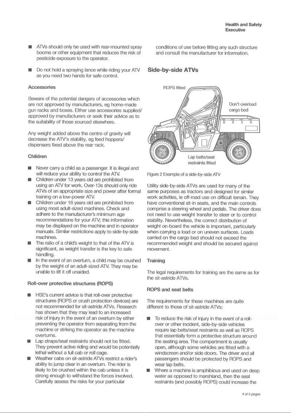
Logic SURFACE PRO LSP150P User manual

LSP150P
SURFACE PRO
USER MANUAL
WM2-LSP150P

2
INDEX
Section:
Description:
Pa e
No:
1Introduction 3
HSE Information Sheet 4-8
2Safety first 9-10
3Instructions / warning decals 11
4ransport lifting and storage 12
5
Operating instructions and adjustments 12
5.1 Attaching to the towing vehicle 12
5.2 Control box attaching to the towing vehicle 13
5.3 Roller adjustment and depth control 13
5.4 ine adjustment 14-15
5.5 Levelling board 15
5.7 Operating speed 16
5.9 Harrowing all weather arenas 17
6Maintenance / service 18
7Specification 19
8
Parts diagrams and List 20
9Logic Manufacturing product owner guarantee 21
Declaration of conformity 22
5.6 Drawbar adjustment 15
5.8 Optional perimeter plough 16
Pro-Harrow Serial Number:
Date of Purchase:

3
INTRODUCTION1
With the purchase of your LSP150P LOGIC SURFACE PRO you have made an excellent choice.
his machine should give first class service for a long time, if used correctly, and maintained as
described in this manual.
Many of today's arenas contain synthetic surfaces incorporating mixed fibres, washed silica sand
and waxed coatings to provide a stable, dynamic and evenly compacted surface.
When you have invested a lot of money on such a sophisticated all weather surface it needs regular
and careful grooming. he LSP150P will maintain the structure and 'feel' of the surface and will
extend the life of the facility.
he LSP150P is built with high quality components throughout to ensure durability and long life.
If after reading this manual there are any queries, please get in touch and we will be pleased to
help.
NORTH & EXPORT SOUTH
LOGIC MANUFACTURING LTD LOGIC MH LTD - New Whitew y Works,
Foundry Industri l Est te Fossecross Industri l Est te
Bridge End, Hexh m Chedworth. Cheltenh m
Northumberl nd NE46 4JL Gloucestershire GL54 4NW
Tel: 01434 606661 F x: 01434 608143 Tel: 01285 720930 F x:01285 720840
E-m il: s les@LogicTod y.co.uk E-m il: s les@LogicTod y.co.uk
www.LogicTod y.co.uk www.LogicTod y.co.uk

4

5

6

7

8

9
SAFETY FIRST2
Please read this manual carefully, adhere to all instructions paying particular attention to the safety
information. For further information or clarification of any of the points made, please contact Logic
Manufacturing Ltd.
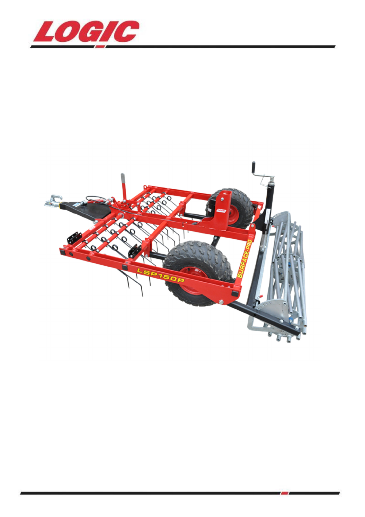
he Logic Surface Pro can be towed by any suitable vehicle from U Vs to Landrovers to 4x4
pickups although it is ideally suited to A Vs
he Logic Surface Pro is not suitable for use with A Vs with less than 300cc engine capacity or for
use with leisure or sports models. 4 wheel drive vehicles are recommended. Using an A V with an
attachment introduces additional risks to operating an A V alone, these should be thoroughly
assessed and managed.
SAFE OPERATION
• Protective clothing must be worn, including a helmet with a visor or goggles, gloves, sturdy
ankle covering footwear and strong clothing that covers your arms and legs. Carry a personal
first aid kit including a large wound dressing.
• Never carry passengers on the Logic surface pro. Individuals under 16 years are forbidden to
use this equipment. Ages 17+ must have been trained in towing equipment or trailers. We
strongly recommend these operators have completed the ‘car and trailer driving test —
category B+E’. hey must also receive additional training and supervision on the daily
operation.
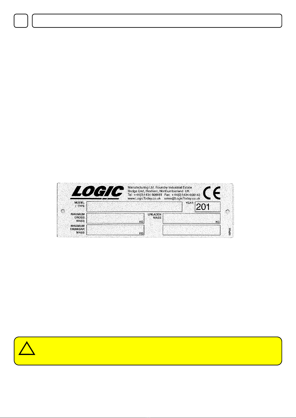
• he gross weight of the Logic Surface Pro can be found of the manufacturers plate which is
riveted to the drawbar.
• he Logic Surface Pro should never be driven at speed. Speed should never exceed more
than 20mph.
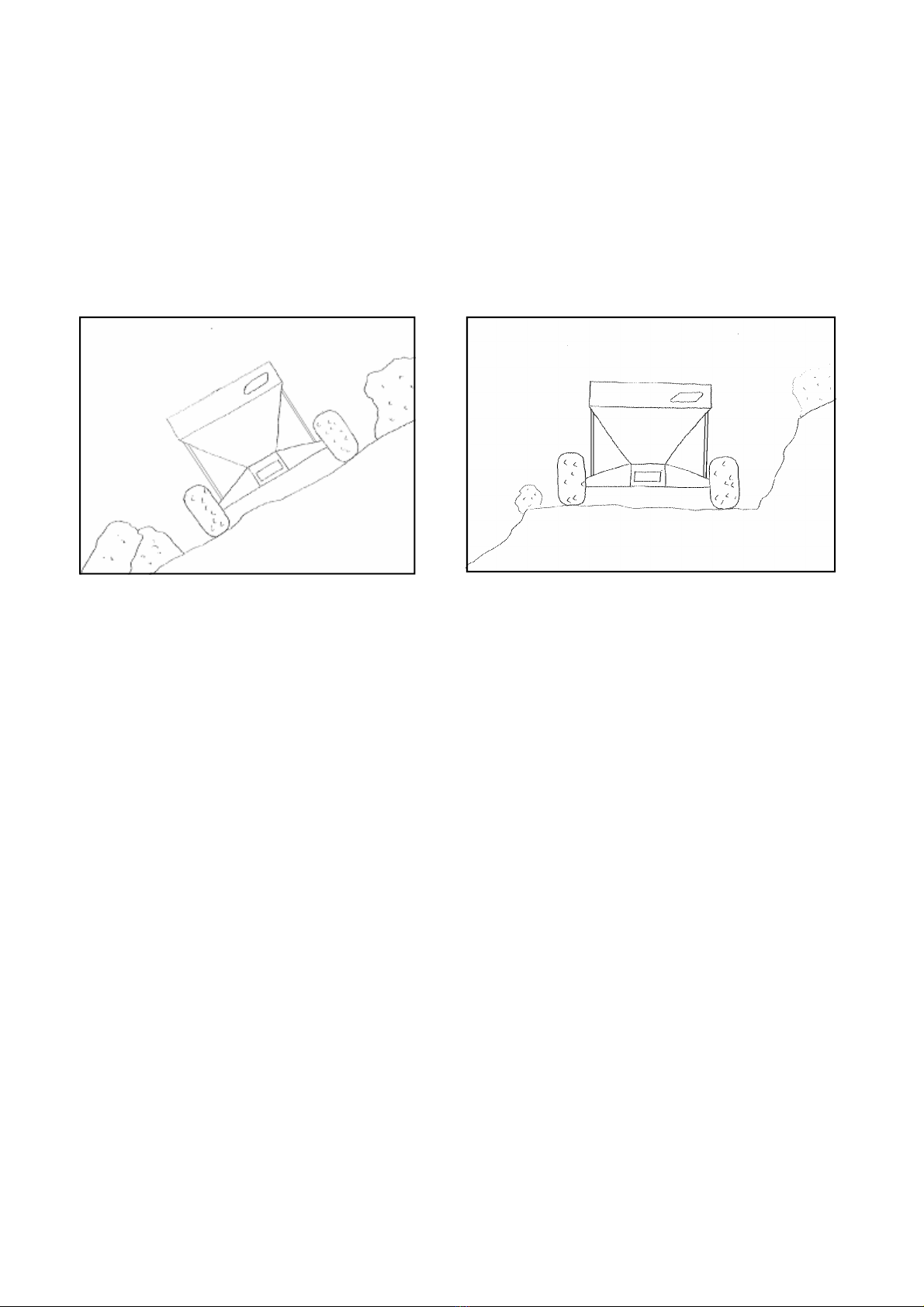
ROUTE PLANNING & ACCESS
• Plan the daily route and access well in advance of using the machine. We recommend you
identify hazards and obstacles including: gates, tracks, public road crossings, field crossings,
hill descents/ascents, sharp corners, unsuitable ground, wet boggy areas, hidden obstacles
(tree stumps, rocks etc). (for more info see HSE Ag info sheet 33 and AFAG701 sheet 39).
• It is the duty of the operators employer, in conjunction with the operators, to identify and plan
the route as part of the health and safety routine planning. A full risk assessment should be
carried out. Logic Manufacturing Ltd accept no responsibility for poor route planning.
If the weather is or has been wet or poor the route should be reassessed before
travelling. Poor weather can affect the terrain being travelled and the handling of the
towing vehicle, especially A Vs
!

10
MAINTENANCE — A WELL MAINTAINED MACHINE IS A SAFER MACHINE
• Maintenance of the towing vehicle and towed equipment should be part of the daily routine.
• he A V should have its brakes, throttle and tyre pressures checked daily. yre pressures are
low on an A V so a 1psi difference can cause vehicle control problems.
• Check that the brakes give a safe straight stop and the throttle operates smoothly in all
steering positions.
• Brakes can have a relatively short life in the environment the machine will be used, so frequent
cleaning, regular adjustment and proper maintenance will be required. he Logic Surface Pro
is unbraked so the towing vehicle is relied upon to provide the control. Check the towing
vehicles manufacturers manual for further guidance.
TRAINING
• here is a legal requirement for employers to provide adequate training for all operators of A V
equipment and attachments. Contact your local HSE office for approved training courses such
as LAN RA for A Vs. he same requirements apply to the self-employed.
DO NOT DO
• he Logic Surface Pro is designed for off road use only.
• Using an A V with a trailed attachment introduces additional risks to operating an A V alone,
these should be thoroughly assessed and managed.
• When navigating slopes, never cross a slope when towing but ride up (ascend) and ride down
(descend) vertically. A track may need to be cut into the bank or slope if it is not possible to
navigate the slope safely. When riding down (descending) always use low gear and delicate
use of controls. Consult your vehicle manufacturer’s manual advice on towing loads up and
down slopes forward speed of the vehicle MUS always be dictated by local ground
conditions, which vary from season to season.

11
3INSTRUCTIONS / WARNING DECALS / STICKERS
he above decals should be located on your LSP150P. If any of the above decals are not
located on your LSH200P or are damaged in any way contact Logic for some
replacement decals before use.
!
!!
!

12
TRANSPORT LIFTING AND STORAGE4
Ensure the vehicle used to lift and transport the harrow has the necessary lifting and loading
capacity. Follow all vehicle manufacturer’s guidelines for lifting.
When lifting the LSP150P for transporting/ delivery purposes always ensure to locate the lifting
straps on each of the four corners ensuring the straps/chains are all the same length before lifting,
or if using forklift tines ensure the harrow is secure on the tines before lifting.
OPERATING INSTRUCTIONS AND ADJUSTMENTS5
he LSP150P is designed to give safe and dependable service if operated according to instructions
and intended use.
Read and understand this manual before operating the unit, as failure to do so could result in
personal injury or equipment damage.
INITIAL CHECK
Make sure that all nuts, bolts and fittings are securely fixed, and that all packaging materials e.g.
wire bands, tape etc have been removed.
5.1 ATTACHING TO THE TOWING VEHICLE
he LSP150P is simply attached by the 50mm ball coupling
he machine is raised and lowered from the transport to work position electrically by the eclectic
actuator. his is shown in figure 1. First time use, level the machine by adjusting the turnbuckle on
the drawbar. See 5.6 on page 15 for more details on adjustment. this will ensure the LSP150P
travels to the work area safely.
Once attached to the towing vehicle take note of the width of the LSH200P compared to the width of
the vehicle.
If the vehicle is fitted with wing mirrors they should be adjusted to allow the user to see the outer
most point of the LSH200P from the driving seat.
Fi ure 1
Electric actuator

13
5.2 CONTROL BOX ATTACHING TO THE TOWING VEHICLE
a. Remove the control box kit from its packaging and lay out on the ground.
b. ake the control box and mount it to the towing vehicle in a reachable place from the
operator.
c. Route the power supply cable to the towing vehicle battery. Ensure the routing does not get
close to any hot areas on the towing vehicle e.g. exhaust.
d. Route the power socket cable to the rear of the towing vehicle and mount the socket as
centrally as possible. he socket comes fitted with clips as standard to attach to an A V rear
rack. hese can be removed for mounting to A V or 4 x 4. Ensure the routing does not get
close to any hot areas on the towing vehicle e.g. exhaust.
e. Connect the harrow plug to the socket and check the harrow lifts up and down.
he control box comes with excess cable length to allow it to be fitted to a U V or 4 x 4 easily.
Fi ure 2
5.3 ROLLER ADJUSTMENT AND DEPTH CONTROL
he LSP150P has infinite adjustment of the rear roller by winding the height adjuster handle shown
in figure 2. he roller controls the depth of penetration the tines at the front of the machine can entre
into the surface being graded.
Note that when the machine is in operation the wheels should be lifted so that they are not touching
the ground therefore transferring the weight of the machine to the rear roller.

14
5.4 TINE ADJUSTMENT
he aggressiveness of the tines on the ground is controlled by the adjustment handle located at the
front of the machine. See figure 3.
he tines have three settings which are designed to give the optimum effect on the ground with the
users desired vehicle.
The more vertical the tines are, the more a ressive their action will be on the round.
Settin 1 is the transport and perimeter plough setting
Settin 2 is the light setting and is for moderate grading
Settin 3 is the highest setting for aggressive grading
he tine angle difference between settings is shown below in figure 4.
Fi ure 3
Settin 1 Settin 2 Settin 3
Fi ure 4
1
2
3

15
ADJUSTING THE TINES
1. Lift the harrow into its transport position.
2. Pull out the spring locking pin located on the adjustment handle at the front of the machine.
3. Move the adjustment handle to the desired setting.
4. Ensure that the spring pin locks the tines in the desired setting.
5. Lower the machine into the work position.
6. Adjust the drawbar turnbuckle to level the machine before use.
Fi ure 5
5.5 LEVELLING BOARD
Levelling Board is set in relation to the rear roller to provide a final levelling of material before
consolidation by the rear roller. his is particularly useful on loose surfaces.
he levelling board is adjusted by the spring bolts on each side shown in figure 5 below.
he levelling bar has a full width handle across the top, to adjust the height pull and lock the spring
bolts back.
Use the handle to move the board then lock the pins back into the holes.
5.6 DRAWBAR ADJUSTMENT
he drawbar on the LSP150P is adjustable to ensure that the machine can be set level for use.
urn the turnbuckle shown in figure 6 below and lock in position with the lock nut.
Fi ure 6
Sprin bolt
Handle

16
5.7 OPERATING SPEED
FORWARD SPEED
In general the LSP150P works best at speed in order to create a vibrating effect with the tines.
Start off at a slower speed and then increase gradually to find the optimum working speed for the
towing vehicle.
he machine should never be driven at excessive speeds which could cause bouncing, resulting in
uneven grading and danger to the operator and any personnel nearby.
MOVING FROM ONE SITE TO ANOTHER
When moving from one site to another simply raise the tines into the transport position, lift the
LSP150P on the control box to full height and proceed with care.
NO E: When using an A V to grade it is very easy to overheat the engine due to the
constant drag and slower operating speeds than normal. Often it is better to reduce
the power requirement by reducing the tine aggressiveness, speed up slightly and go
over the same area twice.
We recommend a minimum requirement of 500cc for an A V engine for use with the
most aggressive tine setting or a more powerful towing vehicle.
!
5.8 OPTIONAL PERIMETER PLOUGH
he optional extra perimeter plough can be used to draw in material thrown up around the side
boards. It is attached to the main frame and incorporates a parking bracket to locate the plough
when not in use. his is shown in figure 7 below. It features a rubber leading edge to prevent any
damage when running along the side boards.
Fi ure 6
Ensure the tines are set in position 1 (transport and plough) this setting lifts the tines clear
of the surface so they will not get damaged if the grader is reversed.
!

17
5.9 GRADING ALL WEATHER ARENAS
Before beginning work the surface needs to be inspected to understand the construction layers of
the surface and to locate the depth of any membranes that may have been incorporated. hese
must be avoided at all costs, but there is usually enough depth above the membrane to allow
reincorporation of the upper materials.
It is always wise to begin with the tines in the least aggressive setting. Move the adjustment handle
to hole 2 – see section 5.4, page 14. Lower the grader onto the surface and set off at a relatively
slow speed to see how the tines are interacting with the surface materials. If there is little
disturbance and minimal re-incorporation happening then lower the tines another hole and try again,
making sure the tines are not too deep to cause damage.
Once you are happy with the action the tines are having at speed, our recommendation is to follow
the sequence of passes to fully cover and level the arena.
Move any obstacles such as jumps to one side to ensure the entire arena is levelled. he surface
can be disturbed the most where a horse has been jumping and turning so it’s vital the jump areas
are harrowed.
(See figure 8)
Consider which direction you want to finish the arena, then work backwards with passes at
an an le to the previous pass.
STAGE 1: Set off at an angle approximately 45 degrees from the side of the arena. his will
cross any well worn routes the horse will have travelled if working the length of the arena.
STAGE 2: he second pass should be at
45 degrees to the first pass and 90 degrees
to the side of the arena so that there is
maximum levelling of the first pass. his
should be carried out at approximately 6-8
mph to create a turbulence between the tines
which will re-incorporate the surface
components.
STAGE 3: he next pass should be in the
direction you wish to leave the arena looking,
prior to any display or exercise work. In this
case the harrow can be reversed into each
corner to rake out the surplus material then
the whole arena harrowed parallel to the
longest side, with the final pass at each end
to level the turning marks.
If the arena has been subject to a lot of hard
use, for example at jumping take off and
landing areas, you may need to have more
localised passes to take out the uneven parts
of the surface before beginning the longer
runs.
Fi ure 8: 3-sta e harrowin technique
1
2
3

18
SERVICE SCHEDULE
DAILY WEEKLY MONTHLY
Check tyre pressures
Check condition of tyres
Visual check to ensure nothing is loose
Check all nuts and bolts
Oil the coupling mechanism and check for wear
Grease all grease points
TYRE / PRESSURE
yre pressure for: Wanda 20 x 7 - 8 (Min 4 Psi M x 10 Psi)
Remember that temperature affects pressures: in cold weather, the pressure needs to be higher
than in higher temperatures.
Never adjust the pressure immediately after driving, because driving heats up the tyres.
here are many individual causes of tyre troubles. However, the three abuses which will cause most
problems, and the greatest costs, are under/over-inflation, overloading and speeding. When you
check the tyre pressures also look for bumps and bulges in the side of the tyre or tread. Check the
tyres for cuts, slits or cracks, nails or foreign objects embedded in the side of the tyre or tread.
Check the tread for excess wear. Replace or repair any defect or fault with tyres before use.
SWIVEL HITCH HOUSING
Check coupling for signs of damage or wear, swivel the coupling 360 degrees and check that the
bushes are not too worn. Replace any worn or damaged parts.
Oil the 50mm coupling; follow the diagrams on the hitch to ensure oil is applied correctly. his is
shown in figure 9.
6MAINTENANCE / SERVICE
!
!!
!
Fi ure 9
DO NOT exceed recommended tyre pressures.
!

19
7SPECIFICATIONS
LSH200P
Max machine width 1557mm
Max machine Height 971mm
Max machine length (Including drawbar) 2622mm
Max working width 1500mm
Weight 208kg
Hitch
50mm ball swivel coupling
Raise / Lower Electric
Wheel / yres WL/ Y 20 x 7 - 8
Max speed 20mph
Spring tines Einbock™
Diameter of tine 8mm
ine spacing 75mm
Number of tines 19

20
8PARTS DIAGRAM AND LIST
Contact Lo ic Manufacturin Ltd for parts information
Table of contents
Popular Farm Equipment manuals by other brands

McHale
McHale F5400 Operator's instruction manual

AGCO
AGCO Cumberland Flex-Flo 220 installation manual

Berthoud
Berthoud BOXER II-1800 manual

Sly France
Sly France BOSS Series operating instructions

Krone
Krone EasyCollect 6000 FP operating instructions

Ziegler
Ziegler PKT 960 Operating instructions and spare parts list