Logitech PRO RACING PEDALS User manual

PRO RACING PEDALS
SETUP GUIDE | GUIDE D’INSTALLATION

ENGLISH . . . . . . . . . . . . . . . . . . . . . . . . .3
FRANÇAIS . . . . . . . . . . . . . . . . . . . . . . . 15
ESPAÑOL . . . . . . . . . . . . . . . . . . . . . . . . 27
PORTUGUÊS . . . . . . . . . . . . . . . . . . . . . . 39

3ENGLISH
FEATURES
1 Clutch Pedal
2 Brake Pedal
3 Gas Pedal
4 Optional Springs
5 Lubricating Grease
6 Allen Key
7 USB Cable
8 Optional Brake Elastomers
1 2
4
7
5
6
8
3

4ENGLISH
CONNECTION AND INSTALLATION
If attaching to a simulation racing rig / seat then please allow
fora maximum depth of 10mm with the M6 bolts that you use.
Note the thickness of the plate / platform that you’re attaching
the pedals to, add that to 10mm and you will then know
thelength of M6 bolt that you need to use. Due to the standard
sizes of M6 bolt lengths you may need to use washers to prevent
longer bolts from encroaching too far inside the pedal unit when
attaching it to your rig. You only need to hand tighten - do not
use power tools to tighten the bolts.
M6X1 L = T + 10MM
10MM
T L

5ENGLISH
Use the included allen key to loosen the two bolts
on the underside of the pedal set and then slide
the module until you have the desired spacing
between each of the pedal modules. Tighten all
bolts to ensure that all of the pedal modules are
securely in place and won’t move during a race.
ADJUSTING PEDAL SPACING
1
2
3

6ENGLISH
The pedal faces can also be adjusted to ne
tune the spacing between the pedal faces,
aswell as the height of the pedal face on
thepedal arm. The Clutch and Brake pedal
faces can beadjusted horizontally and vertically
using theholes provided. The Gas pedal can be
adjusted vertically.
Loosen the two bolts in the pedal face.
Removethe bolts, reposition the pedal face
inthe desired position and then reinsert and
secure the bolts.
ADJUSTING PEDAL FACES
1
2
3

7ENGLISH
All of the pedals can have dierent levels of spring
force applied, using the springs (Gas and Clutch)
and elastomer dampeners (Brake) included in
theaccessory box. The process for starting this is
the same for all three pedals and involves lifting
thepiston out of its location in the pedal module.
The easiest way to achieve this is to wrap your hand
around the pedal face from the front and grip the
knurled edge of the piston body. You then squeeze
the piston to dislocate it from its locking position
using the pedal face / arm as leverage and lift it out
of the cavity in the pedal module where it sits.
ADJUSTING PEDAL SPRING FORCE

8ENGLISH
GAS AND CLUTCH
Once the piston is clear of the main pedal module,
simply pull it away from the steel rod and remove
the spring. There are four springs included in
thebox, two of which are already mounted on
theClutch and Gas pedals. Simply choose one of
the other springs and reverse the process:
Push the spring back over the steel rod and
thenpush the piston back onto the rod,
ensuringthe spring is captured by the two locators.
Then reinsert the piston back into its place,
reversing the process by which you lifted it out:
squeeze the piston using the pedal face / arm as
leverage and then lower it into place, ensuringthat
the bottom of the piston is in the correct
orientation to locate securely.
NOTE:
When you have relocated the piston in place,
trypressing the pedal a couple of times to ensure
that the movement is smooth and free of any noise.
If you notice any noises as you press the pedal,
tryrotating the spring slightly in place and press
thepedal. Keep doing this until you hear no noises.
1
2
6.9 kgf
11.4 kgf
3.9 kgf
8.3 kgf

9ENGLISH
BRAKE
The brake is dierent to the Gas and Clutch
asit uses the elastomer dampeners found in the
accessory box. The procedure is still straightforward
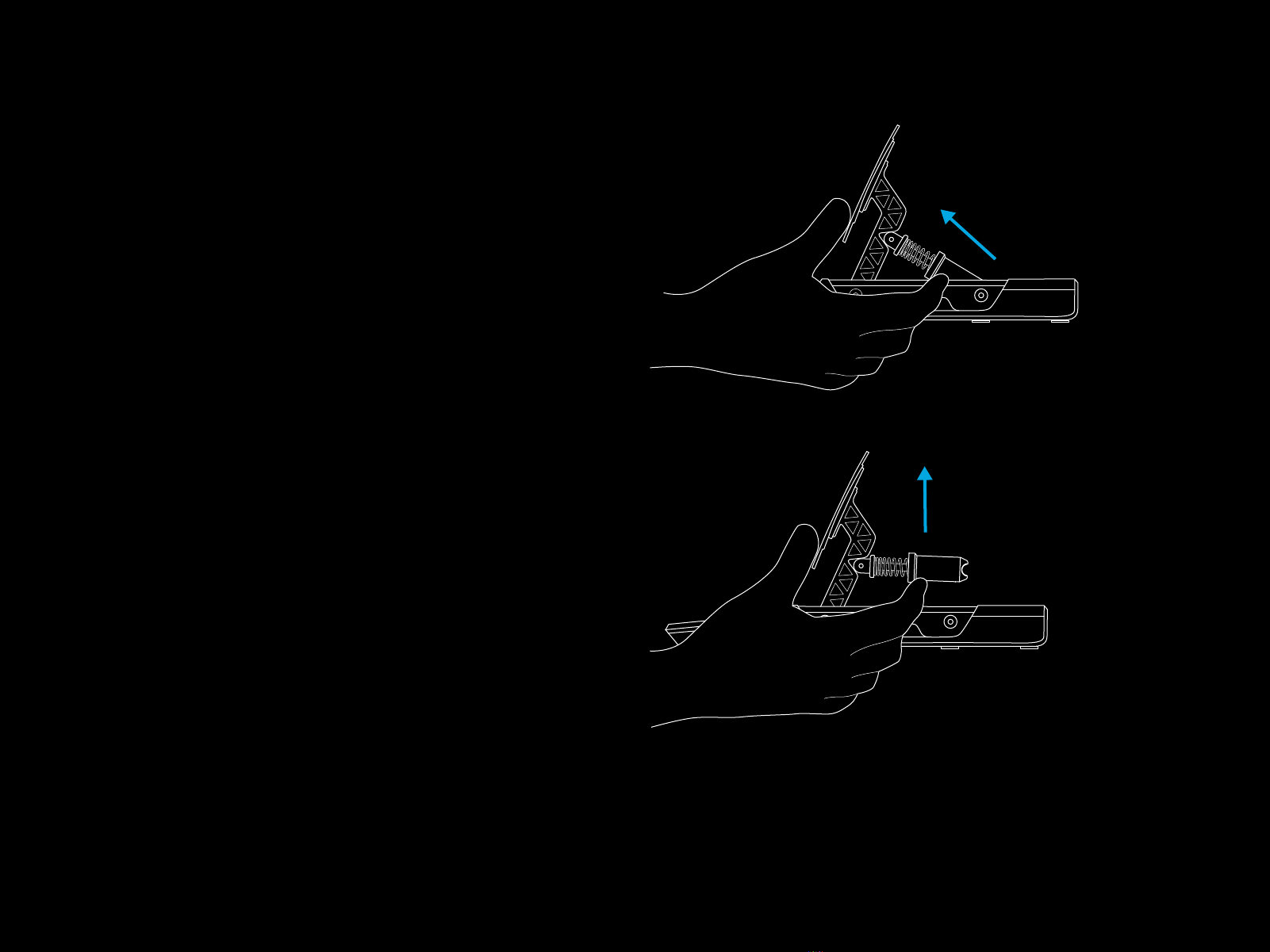
though. Once the piston has been lifted clear from
the pedal module you need to open the piston
inorder to access the elastomer pieces insideit.
Todo this grip the knurled cap at the top of
thepiston in one hand and then unscrew the body
of the piston from the cap.
Once the piston body is removed from the cap,
turnit upside down and shake the elastomer pieces
out. They will be slightly sticky with lubricating
grease so do have something available to wipe
yourhands on.
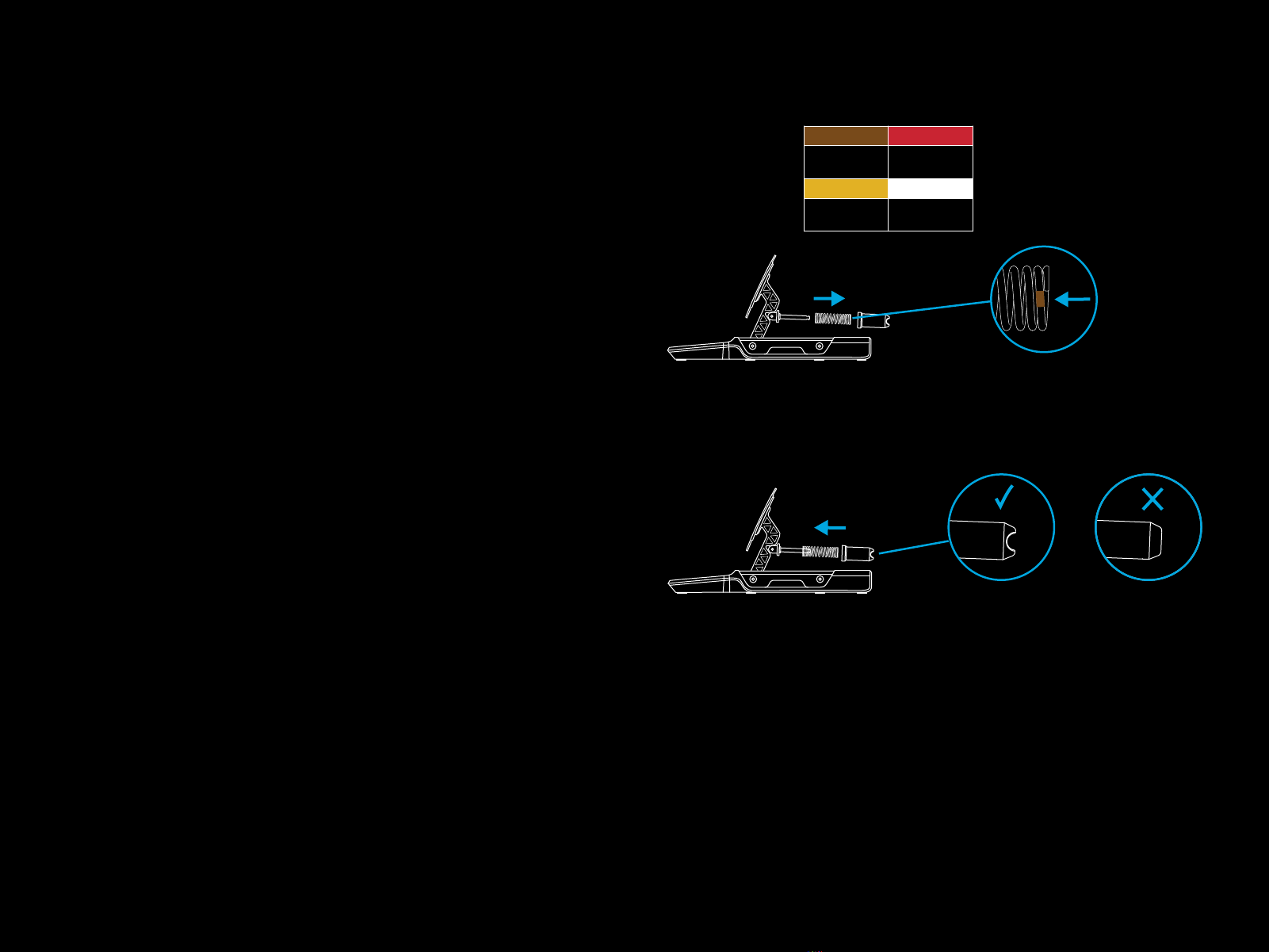
You will notice that there are three pieces of
elastomer or foam in the piston body: two of equal
size and one slightly smaller one. The smaller piece
must always be present in the piston body with
theother two pieces determining the overall feeling
of the brake pedal, enabling you to congure
to be fairly soft with a larger range of travel or,
alternatively, as hard and limited in travel as some
real race cars. Also, the small piece should always
be at the bottom of the piston:

10 ENGLISH
You can alter the feeling of the brake using the
dierent pairings of elastomer pieces as determined
by this table:
You will note that there are two small foam pieces
provided, one soft and one hard - only one of
theseshould be used in combination with two
ofthe larger elastomer pieces.
18 mm
28 mm
33 mm
18 mm
24 mm
29 mm
24mm
28 mm
39 mm
29mm
33mm
39 mm
19 mm
2 9mm
3 4mm
19 mm
25 mm
30 mm
25 mm
29 mm
41 mm
30 mm
34 mm
41 mm

11 ENGLISH
NOTE:
We do not recommend using combinations that include
thesoftbeige piece if the PRO Pedals are hard mounted
intoasimulation rig / seat as this will likely result in damage
tothe elastomer.
Conversely, we do not recommend using the hard elastomers
if you are using the pedals in a desk-based scenario. Unless the
pedals are secured in some manner this could easily result in
thepedals tipping when applying the brake, or the pedals sliding
away from you.
Once you have chosen your elastomer pieces apply a small
amount of the included grease to the sides of the pieces and
insert them back into the piston body remembering to insert
thesmall piece rst. Two or three drops applied to various sides
of the elastomer and spread using the tip of the bottle should be
more than enough.
Once the elastomer pieces are back in the piston body you can
reattach it to the cap on the brake pedal module and then
reinsert it into place using the same method as the other pedals.
SAFETY WARNING:
With the very hard pieces of elastomer (and especially if using
the small hard foam dampener) some strength will be required
to squeeze the piston body enough to enable it to be reinserted
into place. Please do take care to avoid trapping yourngers
between the piston body and the pedal module casing.
Oursuggested method for doing this as depicted in this manual
should help avoid this possibility.
!

12 ENGLISH
CUSTOM PEDAL SETUP
The PRO Racing Pedals have been intentionally designed
to allow anyone to mount the pedal modules in any
manner that they wish. The pedal modules can be
completely removed from the main pedal base that
they are attached to and then mounted into a custom
simulation rig in any orientation to suit your needs.
If you want to create a setup where the clutch and brake
are inverted and the gas is oor mounted then this is
entirely possible. All you need to achieve this are the pedal
modules and the Pedal Hub.
First, unplug the pedal modules from the hub.
Next, remove the bolts holding the pedal modules
on tothe pedal base, taking care not to let them fall
intheprocess. Lift them away from the base and feed
the cable for each module through the holes in the pedal
base, ensuring they don’t get caught.
Next remove the screws holding the Pedal Hub into
thepedal base and lift it out of the base.
You can now mount the pedal modules into your custom
simulation rig as you need them - just connect them
back into the Pedal Hub and then connect the Hub into
your PC or directly into the back of a compatible Logitech
Racing Wheel (if you own one).
G HUB SETTINGS
Your PRO Racing Pedals can be congured using the G HUB
software on PC, whether they’re connected directly to your PC
orinto a compatible Logitech Racing Wheel.
You have the ability to adjust the sensitivity of your pedals and
the amount of pressure required to produce 100% axis output
onthe load cell-equipped brake pedal.
SENSITIVITY
The sensitivity slider enables you to change the linearity of
thepedal response. If you leave it at 50 then this will result in a
1:1 linear response between the physical movement of the pedal
and the axis output to your racing titles. Any adjustment above
or below this will introduce a curve to the axis output;
–As you increase from 50 to 100 then the pedal will become
increasingly responsive at the start of the pedal travel
(meaning you will see a much quicker increase in axis response
at rst)
–As you decrease from 50 to 1 then the pedal will become
decreasingly responsive at the start of the pedal travel
(meaning you will see a much slower increase in axis response
at rst)
It is generally recommended to leave this setting at 50,
buttheexibility is there should you wish to experiment. You can
see the actual response of the pedal here in G HUB; as you press
it you will see the axis response indicator change, so you can
easily see the results of any adjustments that you make.

13 ENGLISH
BRAKE FORCE
This changes how much pressure is required in order
tomake the brake pedal achieve 100% axis output.
Thedefault value is 30, which for the PRO Racing
Pedals equates to 30kg of force; logically therefore
ifyouset thisto the maximum of 100 then 100kg of force
isrequired to achieve 100% axis output.
The amount of force to be used is very subjective
butshould be considered with regards to the following
factors:
–Whether the pedals are mounted into a racing rig,
orsat on the oor
–The actual strength of the person using the pedals
–Which combination of elastomers you have installed
into the brake pedal
For oor-mounted scenarios, 30kg is likely the maximum,
unless the pedals are secured (such as pushed against
a wall under your desk); indeed, lower values are likely
required in order to prevent the pedals from sliding away
from you whilst in use.
For rig-based scenarios, the limit becomes purely
aboutthe overall strength of the rig, the person using
the pedals and the elastomers that you have chosen
touse. As mentioned earlier in the manual, it is strongly
recommended not to use elastomer combinations
thatinclude the softer beige piece when setting forces
higher than 30kg otherwise you could cause damage
tothis through prolonged use.
Due to the onscreen axis response indication it’s easy
to experiment with dierent force settings to see what
suits you the best. A good recommendation, especially
when racing cars without ABS, is to set the force so that
you can’t easily achieve 100% axis output - if youalways
bottom out your brakes then it’s likely to result in
thelocking up of your wheels, losing grip and sliding o
thetrack.
NOTE:
If connected to a compatible Logitech Racing Wheel with
an integrated display then you can also adjust the Brake
Force setting using the wheel, as well as see the response
output of the brake pedal.

14 ENGLISH
COMBINED PEDALS
This is usually only required if using very old racing titles.
Pedals on older racing wheels would often only have
abrake and a gas pedal, with each pedal representing
one half of the same axis. Combined Pedal mode
changes the default conguration of the PRO Racing
Pedals from fully separate axes for the brake and
thegas, to a combined mode, so that you should still
be able to use them in older titles that don’t support
pedals with separate axes.
It is highly recommended for the vast majority of racing
titles that this box is therefore left unticked, in order
toget the most out of your PRO Racing Pedals.
RECOMMENDED MAINTENANCE
Your PRO Racing Pedals have been engineered tocontinue
tooperate for many hundreds of hours and feel as good as
theydid when you rst started using them. As with your real car
though, it is recommended to keep them clean by performing
some simple, semi-regular maintenance.
Regular maintenance (weekly)
Clean the base and each pedal with a damp, lint-free cloth,
ensuring that there is no excess water present inthe cloth
Every 200 hours
Remove any excess built-up grease (especially on thebrake
pedal) using a clean cloth or piece of kitchen towel.
Reapplynewgrease (sparingly) to ensure continued smooth
operation of thepedals.
If you run out of the supplied grease then you may source
areplacement of your own. However, you must only use
asilicone-based grease/lubricant in order to prevent any issues.
Petroleum-based lubricants or Gasoline and Hydrocarbon
solvents must NOT be used as they will degrade the components
used in the pedals.
QUESTIONS?
logitechG.com/support/pro-pedals

15 FRANÇAIS
CARACTÉRISTIQUES
1 Pédale d’embrayage
2 Pédale de frein
3 Pédale d’accélérateur
4 Ressorts en option
5 Graisse lubriante
6 Clé Allen
7 Câble USB
8 Élastomères de frein en option
1 2
4
7
5
6
8
3

16 FRANÇAIS
CONNEXION ET INSTALLATION
En cas de xation à un siège ou à une conguration de course,
prévoyez une profondeur maximale de 10 mm pour les boulons
M6. Vériez l'épaisseur de la plaque/plate-forme sur laquelle
vous allez xer les pédales puis ajoutez-y 10 mm pour déterminer
la longueur du boulon M6 que vous devrez utiliser. En raison
de la taille standard des boulons M6, vous pourriez avoir
besoin derondelles pour empêcher les boulons trop longs de
dépasser du pédalier lorsque vous le xerez à votre plate-forme.
Serrez-lesà la main - n'utilisez pas d'outils électriques pour serrer
les boulons.
M6X1 L = E + 10mm
10mm
E L

17 FRANÇAIS
Utilisez la clé Allen fournie pour desserrer
lesdeuxboulons situés sous le pédalier,
puisfaites glisser le module jusqu'à ce que vous
obteniez l'espacement souhaité entre chaque
module de pédales. Serrez tous les boulons
pourvous assurer que les pédales restent bien
enplace et ne bougent pas pendant la course.
RÉGLAGE DE L'ESPACEMENT DES PÉDALES
1
2
3

18 FRANÇAIS
Les pédales peuvent également être ajustées
pour aner l'espacement entre les revêtements
des pédales et la hauteur sur le bras de la pédale.
Les pédales d'embrayage et de frein peuvent
être réglées horizontalement et verticalement
à l'aide des trous prévus à cet eet. La pédale
d'accélérateur peut être réglée verticalement.
Desserrez les deux boulons sur le revêtement
dela pédale. Retirez les boulons,
repositionnezlerevêtement de la pédale
danslaposition souhaitée, puis remettez
etxezles boulons.
RÉGLAGE DES REVÊTEMENTS DE PÉDALE
1
2
3

19 FRANÇAIS
Les ressorts peuvent appliquer diérents niveaux
deforce aux pédales (accélérateur et Embrayage)
etaux amortisseurs élastomères (Frein) inclus dans
la boîte d'accessoires. Le processus de démarrage
est le même pour les trois pédales: soulevez le piston
de son emplacement dans le module de la pédale.
Pour y arriver facilement, enroulez votre main
autour du revêtement de la pédale par l'avant
etsaisissez le bord moleté du piston. Faites ensuite
pression sur le piston pour le déloger de sa position
de verrouillage en utilisant le revêtement/le bras
dela pédale comme levier et sortez le de la cavité
où il se trouve.
RÉGLAGE DE LA FORCE DES RESSORTS DES PÉDALES

20 FRANÇAIS
ACCÉLÉRATEUR ET EMBRAYAGE
Une fois que le piston est dégagé du module
principal de la pédale, il sut de l'éloigner de la
tige en acier et de retirer le ressort. Quatre ressorts
sont inclus dans la boîte, dont deux déjà montés
sur lespédales d'accélérateur et d'embrayage.
Choisissez simplement l'un des autres ressorts
etinversez le processus:
Poussez le ressort sur la tige en acier, puis poussez
lepiston sur la tige, en veillant à ce que le ressort
soit bien verrouillé par les deux localisateurs.
Remettez ensuite le piston en place en inversant
le processus: serrez le piston en utilisant le
revêtement/le bras de la pédale comme levier,
puisabaissez-le pour le mettre en place, en veillant
à ce que le bas du piston soit dans le bon sens.
REMARQUE:
Lorsque vous aurez remis le piston en place,
essayezd'appuyer sur la pédale à quelques reprises
pour vous assurer que le mouvement est régulier
et silencieux. Si vous remarquez des bruits lorsque
vous appuyez sur la pédale, essayez de faire tourner
légèrement le ressort et appuyez sur la pédale.
Continuez jusqu'à ce que vous n'entendiez plus
aucun bruit.
1
2
6,9 kgf
11,4 kgf
3,9 kgf
8,3 kgf
Other manuals for PRO RACING PEDALS
1
Table of contents
Languages: