Logitex LX ACDC/M+K 125 A Specification sheet

Patented product
OPERATING AND
INSTALLATION MANUAL
Tank-type water heaters for combined water
heating by means of AC/DC current
for vertical assembly
LX ACDC/M+K 100 A,B,C
LX ACDC/M+K 125 A,B,C
LX ACDC/M+K 160 A,B,C
LX ACDC/M+K 200 A,B,C
LX ACDC/M+KW 200 A,B,C
MANUFACTURER:
LOGITEX spol. (co.) s.r.o. (Ltd.) ,
Športovcov 884/4, SK - 02001 Púchov
Phone no.: +421/42/4710200
Made in:
Družstevní závody Dražice – strojírna s.r.o. - Works
Cooperative - Dražice – Machine Plant, Ltd.
Dražice 69, CZ - 29471 Benátky nad Jizerou
Tel.: +420 /326 370 990
CAREFULLY READ THIS MANUAL BEFORE INSTALLING THE WATER HEATER!

- 2 -
CONTENTS
1 Information for customers ......................................................................................................................... 4
2 Function of the heater:............................................................................................................................... 7
3 Servicing ..................................................................................................................................................... 8
3.1 Control panel ...................................................................................................................................... 8
4 Technical description.................................................................................................................................. 9
4.1 Diagram of: LX ACDC/M+K 100 A,B,C; LX ACDC/M+K 125 A,B,C; LX ACDC/M+K 160 A,B,C; LX
ACDC/M+K 200 A,B,C ..................................................................................................................................... 9
4.2 DIAGRAM OF LX ACDC/M+KW 200 A,B,C ........................................................................................... 9
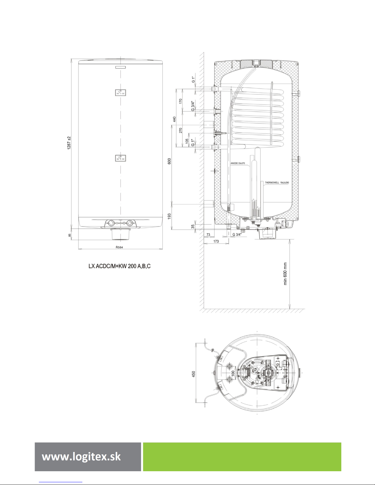
4.3 DIMENSIONS OF THE LX ACDC/M+KW 200 A,B,C HOT WATER HEATER ........................................... 10
4.4 DIMENSIONS OF: LX ACDC/M+K 100 A,B,C; LX ACDC/M+K 125 A,B,C; LX ACDC/M+K 160 A,B,C; LX
ACDC/M+K 200 A,B,C ................................................................................................................................... 11
5 Operating activity ..................................................................................................................................... 11
6 Accessories ............................................................................................................................................... 12
7 Wall mounting.......................................................................................................................................... 12
8 Plumbing fixture ....................................................................................................................................... 12
9 Connection of a combined heater ............................................................................................................ 14
10 Electric wiring ........................................................................................................................................... 14
10.1 Wiring diagram: ................................................................................................................................ 15
11 Fire-fighting regulations for installation and use of heater ...................................................................... 17
12 Connecting the heat exchanger for LX ACDC/M+KW 200 A,B,C ............................................................... 17
13 Important NoticeS .................................................................................................................................... 18
13.1 Disposal of packaging material and non-functioning product .......................................................... 18

- 3 -
Meaning of pictograms used in the Manual
Important information for heater users.
Abiding by the recommendations of the manufacturer serves to ensure trouble-free
operation and the long service life of the product.
Caution!
Important notice to be observed.
The product’s reliability and safety have been verified by tests implemented by EVPÚ Nová
Dubnica.
The manufacturer reserves the right for engineering modification of the product. The product
is designed for permanent contact with drinkable water.
To ensure proper functioning, the water heater must be connected to a permanent power
supply.
Installation may only be performed by a person authorised to carry out electric
installations.

- 4 -
1INFORMATION FOR CUSTOMERS
LX ACDC/M+K(W) A,B,C type electrical and combined water heaters utilise alternating (AC) current from
the electric grid, e.g. from a 230V socket, and direct (DC) current from photovoltaic panels, which ensure
the ecologically clean production of hot water and save significant financial sources for the user by
minimising consumption of gas or electricity from the grid.
In addition, due to the separate systems, the water heater first heats using photovoltaic panels, and in
the case of cold water, it supplements heating using electricity from the 230V grid.
In addition, the LX ACDC/M+KW A,B,C model has a shifted tubular heat exchanger for
providing heat from another source, or, on the contrary, by using heat from the water
heater. Information on connecting this model can be found in Chapter: 12 –Connecting
the heat exchanger for LX ACDC/M+KW 200 A,B,C.
LX ACDC/M+K(W) A,B,C water heaters are meant to be used with various kinds of FV
panels from various manufacturers. They must however embody the following qualities:
Voltage: 30V ±10% and Current: 8.3A ±5% / 1 FV panel!
Photovoltaic panels can be installed at any place with maximum sunshine and south oriented, but must
not be freely accessible due to the fact that they produce electric energy and there is a risk of electrical
injury. Therefore always let an authorised service company deal with the assembly. For DC supply, water
heaters are designed for:
4 pcs panels with an output of 250W/1 panel - 1,0kW/120V (A)
6 pcs panels with an output of 250W/1 panel - 1,5kW/180V (B)
LXACDC/M+K(W) A,B,C are equipped with a universal DC heating element, which enable all
3 variants of output: A,B a C, with the help of a mechanical reconnection of the inlet
conductor, directly on the heating element. During production, the heating element is
always connected to 2kW (8 pcs of panel). If a lower number of panels is used (4 pcs
=1.0kW and 6 pcs=1.5kW) 1. This reconnection may be performed solely by a
professionally trained individual!
8 pcs of panel with an output of 250W/1 panel - 2.0 kW/240V (C)
The above stated outputs must not be exceeded for the respective types!
It is possible to use panels with a lower output, however the output of the heating element running on
DC current will decline proportionately.

- 5 -
Figure 1
Before each intervention into the inner parts of the construction of the water heater, it is
necessary to always disconnect from both sources of AC and DC current!
Accumulation water heaters with combined heating using AC and DC current may be used to heat water by
AC current only from the grid, or by DC current from photovoltaic panels or simultaneously, in various
combinations of temperatures set by means of two separate thermostats. LX water heaters are even meant
for pre-heating and supplementary heating of water. This type of use is suitable as a supplementary system
for already existing system of water heating for users using a system in which the heater is placed before or
after the system. All water heaters of the M+K(W) line are equipped with a tubular heat exchanger, which
allows them to connect to an external heat source (furnace, fireplace, natural gas heater, and the like). For
M+KW models that are made only in the 200L version, the tubular heat exchanger is located in the upper
part of the heater. That type of solution enables the top half to be heated by gas and the bottom half by
photovoltaic panels and once the temperatures are in balance, then all 200L of the water heater only by
photovoltaic panels. The M+KW model can also be utilised as a source of power for floor heating in low-
energy and passive homes.

- 6 -
OPERATION & ASSEMBLY REGULATIONS FOR WATER HEATERS:
Type: electric
Type: combined with a 1 m2heat exchanger
*) This value specifies the maximum output, which the exchanger is able to transfer to the water in
the heater, while connecting the exchanger to an external source of heat. For the LX ACDC/M+KW 200 A,B,C
model for when connecting the exchanger to a system of floor heating which utilises heat from the water
heater. The output therefore depends on the actual amount of heat accumulated in the heater.
LX ACDC/M+K(W) A,B,C water heaters are mainly intended to utilise both electric energy sources. A stable
source of AC current from the grid permanently heats water to a temperature that is set using the T1
thermostat. In practice, the recommended temperature is 450 C. Upon reaching the pre-set temperature,
the T1 thermostat switches off the inlet of AC current. DC current from photovoltaic panels keeps heating
the water to the preset temperature on thermostat T2.
If the water temperature drops (water withdrawal) to below 45°C with the sun shining, the water is very
quickly and effectively heated by both sources of current. In the winter period (from 1.Nov.-1.Mar.), we
recommend setting thermostat T1 to a higher temperature due to weaker sunshine.
WARNING: The thermometer on the water heater measures the temperature of the metal
water container, and therefore there may be deviation from the actual water
temperature.
Type
LX
ACDC/M+K
100 A,B,C
LX
ACDC/M+K
125 A,B,C
LX
ACDC/M+K
160 A,B,C
LX
ACDC/M+K
200 A,B,C
LX ACDC/M + KW
200 A,B,C
Electrical current for
heating
AC+DC
AC+DC
AC+DC
AC+DC
AC+DC
Heat losses [kWh/24h]
0,88
1,09
1,39
1,4
1,4
Capacity [l]
95
120
147
195
195
Weight [kg]
58
64
72
88
88
Height x diameter [mm]
881 x 524
1046 x 524
1235 x 524
1287 x 584
1287 x 584
Power input of AC coil
[kWh]
2
2
2
2
2
Exchanger heat transfer
surface [m2]
1
1
1
1
1
Rated thermal output at
heating water
temperature of 80°C and
flow 720l/h l/h [kW]
24
24
24
24
24*
Table 1

- 7 -
2FUNCTION OF THE HEATER:
Water heating by electric energy
Once connected to the electric grid (230V AC), the heater is ready to heat water. Even in the case of water
heating using only DC current, it is necessary to connect the heater to the electrical grid (230V). Electricity
consumption from the network is minimal when the T1 thermostat is off, and represents a value of 0.0039
kW. To heat water using DC current from photovoltaic panels, the desired temperature has to be set on
thermostat T2. When the sun is shining, the panels produce current, which heats the heating spiral of the
water heater. The switching on and off of spiral heating is controlled by thermostats.
The thermostats can be set as needed within the range of 5°C to 74°C. We recommend setting the water
temperature while heating with DC to a maximum temperature of 70°C. This temperature ensures the
optimal utilisation of the electric source from photovoltaic panels.
After reaching the set temperature, the thermostat switches off the electricity supply and
discontinues water heating.
The orange control light indicates that the device is in operation. If it is on, the device is running.
If it goes off, the device is out of service.
The green control light signalizes the input of the direct current from the photovoltaic panels. If
it is on, the panels are producing electrical energy.
Heating water by means of AC current from network is indicated by a red control light. If it
goes off, heating of water by AC current is off.
Caution! Water heated to 70°C is very warm to the touch. To use it, it has to be mixed with
cold water.
The manufacturer recommends mounting of a mixing valve to the hot water outlet and setting
a maximum temperature on thermostat T2. On sunny days the temperature in the heater can
achieve up to 90°C, which is a temperature that, in case of scalding, may cause health
complications. Output temperature suitable for general use shall be set on the mixing valve.
The closing valves of the tubular heat exchanger must be opened, which ensures heating water flow from the
hot water heating system. Along with a closing valve at the inlet to the heat exchanger, it is recommended to
install an air removal valve, in order to bleed the heat exchanger as needed, in particular before the
beginning of the heating season. The time it takes to heat up using the heat exchanger depends on the
temperature and flow of water in the hot water heating system. Combined heaters are made with a
universal design, i.e. the outlets of the exchanger exit at the rear of the heater, for cases when it is necessary
to either connect from the right or left.

- 8 -
3SERVICING
3.1 CONTROL PANEL
The heater tank is made of a steel plate and tested at 0.9 MPa of overpressure. The inside of the
tank is enamelled. A flange is welded onto the bottom of the tank with a flange lid screwed to it.
A sealing ring is inserted between the flange lid and the flange to ensure perfect tightness. There
are wells for the placing of heating, regulation and safety elements for water heaters in the
flange lid (heating element, thermostat sensor and thermal fuse). An anode rod is mounted onto
the M8 nut.
In combined versions, a heat exchanger is welded onto the pressure tank.
The anode rod is used as a secondary protection for the heater tank. Through its reaction with
water, it creates an environment that prolongs the lifetime of the tank. The design of the anode
and the material used comply with the standard EN 12438.
A thermometer, that transmits information on the temperature of water in the accumulation
heater, is installed in the top part of the heater.
The accumulator is insulated by means of polyurethane foam that ensures minimal heat losses.
Electric wiring is placed in the bottom part of the heater, under an easily removable guard.
Temperature of water can be set by thermostats within the range between 5°C and 74°C
according to the scale marked thermostat regulators.
Cold water inflow is indicated with blue, hot service water (the “HSW” hereinafter) outflow is
indicated in red. All external steel parts are protected against corrosion with a powder baking
paint; connecting pieces are metal plated.

- 9 -
4TECHNICAL DESCRIPTION
4.1 DIAGRAM OF: LX ACDC/M+K 100 A,B,C; LX ACDC/M+K 125
A,B,C; LX ACDC/M+K 160 A,B,C; LX ACDC/M+K 200 A,B,C
Figure 2
4.2 DIAGRAM OF LX ACDC/M+KW 200 A,B,C
Figure 3

- 10 -
4.3 DIMENSIONS OF THE LX ACDC/M+KW 200 A,B,C HOT WATER
HEATER
Figure 4

- 11 -
4.4 DIMENSIONS OF: LX ACDC/M+K 100 A,B,C; LX ACDC/M+K 125
A,B,C; LX ACDC/M+K 160 A,B,C; LX ACDC/M+K 200 A,B,C
Figure 5
5OPERATING ACTIVITY
The heater operates on a pressure principle which means that there is constant water pressure from the
water supply conduit in the tank.
If the combination faucet hot water valve is opened, the water from the water supply conduit pressed out by
cold water pressure flows out of the heater. Hot water flows out through the top part, and water flowing in
remains in the bottom part of the heater.
LX ACDC
100/M+K
A,B,C
LX ACDC
125/M+K
A,B,C
LX ACDC
160/M+K
A,B,C
LX ACDC
200/M+K
A,B,C
A
881
1046
1235
1287
B
876
1041
1230
1282
C
636
801
1005
793
D
524
524
524
584
E
701
701
701
685
F
551
551
831
895
G
G1"
G1"
G1"
G1"
H
G3/4"
G3/4"
G3/4"
G3/4"
I
261
261
261
245
J
-
-
815
600

- 12 -
6ACCESSORIES
The product comes with a safety valve and a thermometer. Hinges and bolts are mounted onto the heater. It
is in your own interest to check the completeness of the accessories.
With regard to various types of carrying masonry and broad assortment of special anchorage material
available at the market, the manufacturer does not provide heaters with this material. The anchorage
system has to be selected individually, depending on the conditions. We recommend an authorised company
perform mounting on the wall and anchorage, or discuss the anchorage with a professional.
7WALL MOUNTING
Prior to mounting, check the loading capacity of the wall, If needed, reinforce it. Choose a suitable anchorage
material to suspend the heater, depending on the type of the wall. The water heater shall only be mounted
in vertical position so that the lower edge of the heater is placed at least 60 cm above the floor.
8PLUMBING FIXTURE
Connection of heaters to plumbing fixtures is illustrated on Figure 6. For potential disconnection of the
heater, the service water inlets and outlets must be provided with screw coupling Js 3/4“. For operation, the
heater must be equipped with a safety valve. The safety valve is mounted on the cold water inlet identified
with a blue ring.
Each hot service water pressure heater must have a safety valve with a membrane spring.
The safety valve must be easily accessible, as close to the heater as possible. The inlet pipes must have at
least the same clearance as the safety valve. The safety valve is placed high enough to secure dripping water
drain by gravity. Safety valves with fixed pressure settings from the manufacturer are used for the assembly.
The start-up pressure of the safety valve must correspond to the max. allowed pressure of the water heater.
If the water main pressure exceeds such value, a reduction valve must be added to the system, whose
working pressure is to be set to 80% of the start-up pressure of the safety valve. Necessary pressure can be
found in table 2. No stop valves can be put between the heater and the safety valve. During assembly, follow
the guide provided by the safety equipment manufacturer. It is necessary to check the safety valve each time
before putting it into operation. It is checked by manual moving of the membrane from the seat, turning the
make-and-break device button always in the direction of the arrow. After being turned, the button must click
back into a notch. Proper function of the make-and-break device results in water draining through the safety
valve outlet pipe. In common operation, such a check needs to be implemented at least once a month, and
after each heater shutdown for more than 5 days. Water may be dripping off the drain pipe of the safety
valve; the pipe must be open into the air, pointed down; environment temperatures must not drop below
zero.

- 13 -
When draining the heater, use the recommended drain
valve. First, close the water supply into the heater. For
proper safety valve operation, a backflow valve must be
mounted on the inlet pipes, preventing spontaneous
heater draining and hot water penetrating back into the
water main.
Hot service water is withdrawn by means of a combination
faucet from the outlet pipe marked with red colour. If
HSW distribution is longer, it should be insulated to
minimise heat losses. All outlets must be equipped with
combination faucets that allow setting the desired
temperature of water.
NOTICE
If the safety valve isn’t equipped with a drain opening, we recommend adding a drain valve
in a suitable location before the safety valve. If the pressure in the water piping exceeds 0.6
MPa, we recommend installation of a pressure control valve, as well. The appliance is not
designed to be serviced by people (including children) with limited physical, sensual or
mental abilities, or those having lack of experience and knowledge, unless a person
responsible for their safety provides supervision or familiarise them with the way of using
the appliance.
Safety valve:
TE-2852, DN20 –direct safety valve with inner connecting threads inside the body
Technical data:
Maximum pressure 0.6 MPa
Safety overpressure 0.63 + 0.03 MPa
Figure 6
Start-up
pressure of
the safety
valve [MPa]
Allowable
operational
overpressure
of the water
heater [MPa]
Maximum
pressure in
the cold
water pipes
[MPa]
0,6
0,6
up to 0.48
0,7
0,7
up to 0.56
1
1
up to 0.8
Water installation must follow and meet the requirements and
regulations relevant in the country of use.
Table 2

- 14 -
9CONNECTION OF A COMBINED HEATER
It is recommended to install stop valves on the heating water inlet and outlet (for possible
dismantling of the heater).
The valves have to be as close to the heater as possible to avoid higher thermal losses.
In combined versions, the stop valve on the inlet to the exchanger has to be closed at the
inlet to the tubular heat exchanger while heating using el. energy, which prevents heating
water in the hot water heating system.
In the case that the heat exchanger isn’t utilised, it is necessary to leave the plastic stoppers
on the outlets of the heater (from manufacturer), so that air doesn’t circulate in the heat
exchanger’s spaces.
10 ELECTRIC WIRING
Connection, repairs, and wiring inspections may only be implemented by a person authorised
to such activity. Electric installation must comply with valid electro-technical standards.
Connection to electric network shall be executed only after the plumbing has been installed.
Elements for disconnection from the electric grid must be built into the fixed electric grid
distribution that contains separation of contacts in all positions.
Electric installation must follow and meet the requirements and regulations relevant in the
country of use.
Connecting the LX ACDC/M+K(W) A,B,C heater facilitates the connection of two inlets and one
outlet. The outlet is meant for direct current.
To control photovoltaic supply, the system has to be connected to the power grid from the
nearest continuous supply (socket), into 230V clamps: L, N and PE.
The following safety elements are recommended for installation of photovoltaic
system:
1) SPD type 1 lightning diverter (e.g. SLATEK FLP-500 PH V/2, FLP-500 PH V/25)
2) Direct current circuit breaker (e.g. Moeller X pole PL7-C16/2-DC). This circuit breaker
must be designed according to the characteristics of the panels. The maximum value of
protection is stated by the manufacturer in the parameters of the photovoltaic panels.

- 15 -
10.1 WIRING DIAGRAM:
Figure 7
T1 Thermostat for DC heating S1 - Indicator lamp of connection to power grid
T2 Thermostat for AC heating S2 Indicator of DC spiral activity
TP Heat fuse S3 Indicator of AC spiral activity
St1 Contactor for switching on FV heating St2 Contactor for switching between
R1 AC Heating element R2 DC Heating element (photovoltaic)
Before any manipulation with the connections of the water heater, make sure that all inputs
of AC and DC current are disconnected!

- 16 -
For clamps + and –with arrow facing out it is possible to connect a DC/AC converter, or
another appliance with direct DC current. (Battery, another LX ACDC heater)
These clamps don’t need to be connected.
Clamps N, L and PE serve for the connection of alternating AC current. Without connecting
these clamps, the heater is not functional!
Clamps +and –with arrow facing in are meant for connection to PV panels.
After connecting the heater to the water distribution system, electrical power system and
source of current from photovoltaic panels, and after testing the safety valve (following the
instructions attached to the valve) the heater can be put into operation.
Procedure:
a) Check the plumbing and electrical installation, including the connection to hot-water heating
system. Check proper placement of operating and safety thermostat sensors. The sensors in
the well must be inserted all the way in; first the operating and then the safety thermostat.
b) Open the hot water valve on the combination faucet.
c) Open the cold water inlet valve to the heater.
d) As soon as the water starts running through the hot water valve, the heater is filled and the
valve closes.
e) In case of a leakage (flange lid), we recommend fastening the flange lid bolts.
f) Connect the water tank to alternate current electric network
g) Connect the water tank to direct current source from photovoltaic panels.
h) Prior to putting the heater into operation, screw the electric installation guard to the heater
which closes the access to the electric compartment of the heater. During water heating,
water occasionally drips through the safety valve which is a normal phenomenon caused by
growing volume of water.
i) Rinse the heater out before you start using it.

- 17 -
11 FIRE-FIGHTING REGULATIONS FOR
INSTALLATION AND USE OF HEATER
12 CONNECTING THE HEAT EXCHANGER FOR LX
ACDC/M+KW 200 A,B,C
Figures 8 and 9 show the scheme for connecting the LX ACDC/M+KW 200 A,B,C for floor heating systems for
low-energy and passive homes.
Figure 8
Fire-fighting regulations for heater installation are defined in relevant standards.
The heater must not be connected to power supply and direct current source of photovoltaic
panels if work involving flammable liquids (petrol, spot remover) or gases, etc., is performed
nearby.

- 18 -
Figure 9
13 IMPORTANT NOTICES
Both the electric and water installation must follow and meet the
requirements and regulations relevant in the country of use!
13.1 DISPOSAL OF PACKAGING MATERIAL AND NON-
FUNCTIONING PRODUCT
A service fee for providing return and recovery of packaging material has
been paid for the packaging in which the water heater was delivered. The
service fee was paid in accordance with Act no. 477/2001 Coll., as
subsequently amended, at EKO-KOM a.s. The client number of the company is
F06020274. Take the water heater packages to a waste disposal place
determined by the municipality. When the operation terminates, disassemble
and transport the discarded and unserviceable heater to a waste recycling
centre (collecting yard), or contact the manufacturer.
1-2014
This manual suits for next models
14
Table of contents
Popular Water Heater manuals by other brands

Heatrae Sadia
Heatrae Sadia PremierPlus Installation and user manual

clage
clage CBX 11 Operating and Installing Instructions

A.O. Smith
A.O. Smith DEL Installation and operaion manual

Raypak
Raypak 260-401 Installation and operating instructions

Bryan Boilers
Bryan Boilers Knockdown RV-500 Specifications

Craftsman
Craftsman CMXTEPA0018 instruction manual

IBC
IBC SFT Series User's information manual

Reflex
Reflex Variomat VS 1 operating manual

Vaillant
Vaillant atmoSTOR VGH classic 130/6 Z Instructions for use and installation

Solo
Solo 80 00 150 Mounting instructions

A.O. Smith
A.O. Smith BFM 30 installation instructions

Atwood
Atwood MPD 93755 Installation operation & maintenance