LONCIN 900 Mini teller User manual


1
Foreword
Thank you for purchasing our mini tiller
It is the accelerator for your building of a richer life.
With a small size, a light weight, multiple functions, high rotary tilling efficiency, ability to work on
mountains, in waters, to cross ridges of fields and ditches, and easy transport and operation of turning around,
this model of mini tiller is especially suitable for work in mountain areas, hilly areas, arid fields, irrigated
fields, orchards, gardens, arch-roofed sheds, etc.
Its basic functions include rotary tilling, trenching, ridging and transportation. With the help of
appropriate accessories, it can also used for pumping, irrigation, insecticide spraying, harvesting, power
generating, fertilizing, seeding, seed extraction, threshing, climber cutting, grinding to produce thick liquid,
etc., besides, it is simple in structure, easy to maintain and repair, and fuel-efficient, all these features make it
an ideal mini farming machine.
It is a good helper for building a richer life of your family.
Warning! Unauthorized reproduction of this manual or any part of it for any other purpose is prohibited;
when the mini tiller is resold, this manual, as part of the mini tiller, shall be transferred with the mini tiller.
Warning! Please pay special attention to the following information:
Please read carefully this operation and maintenance manual before operation and strictly comply with
the manual while operating. If you operate in compliance with the manual, the mini tiller designed by our
company can work safely and reliably without damage to equipment and personal injury. Should you not
operate in compliance with the manual, there may occur severe damage or injury to your equipment or your
body.
Note! Should there be any problem with the machine, or should you have any doubt about it, please contact
our company’s local sales agent.
Let’s join our hands to create a better life!

2
Thank you
Contents
Chapter I Safety warnings ………………………………………………………………………………4
Chapter II Safety symbols ………………………………………………………………………………8
Chapter III Brief introduction of mini tiller ……………………………………………………………10
i. Major technical parameters …………………………………………………………………… 10
ii.Names of major parts and components of mini tiller…………………………………………… 11
Chapter IV Operation method of the mini tiller …………………………………………………………12
i. Assembly after unpacking…………………………………………………………………………12
ii. Installation and adjustment of cables ……………………………………………………………12
iii. Check and oiling…………………………………………………………………………………14
iv. Starting …………………………………………………………………………………………17
v. Operation………………………………………………………………………………………… 17
vi. Connection and operation of attached parts………………………………………………………18
vii. Precautions for use of mini tiller…………………………………………………………………19
Chapter V Maintenance of mini tiller ……………………………………………………………………19
i. Running in ……………………………………………………………………………………… 19
ii. Technical maintenance of mini tiller ……………………………………………………………20
iii. Technical maintenance schedule of mini tiller …………………………………………………21

3
iv. Long storage of mini tiller………………………………………………………………………22
Chapter VIAdjustment method of mini tiller……………………………………………………………22
i. Method of adjusting reverse cable ………………………………………………………………22
ii. Method of adjusting clutch cable ……………………………………………………………… 22
iii. Method of adjusting accelerator cable …………………………………………………………23
iv. Method of using and adjusting handle pipes ……………………………………………………23
Chapter VII Trouble shooting of mini tiller …………………………………………………………… 25
i. Trouble shooting of clutch ………………………………………………………………………25
ii. Trouble shooting of transmission box……………………………………………………………26
iii. Trouble shooting of running mechanism ………………………………………………………28
iv. Trouble shooting for other parts…………………………………………………………………29

4
Chapter I Safety warnings
1. Training
a) Carefully read the operation manual. Get fully familiar with the correct method of
operation of this machine and its mechanisms. Understand how to stop it and how to quickly
disengage the operation mechanism.
b) No child is allowed to use the machine! No adult is allowed to use the machine before
carefully reading the manual!
c) Ensure no other persons or things with potential safety risk, especially children and pets,
are inside the working area!
2. Preparation
a) Thoroughly check the area for the machine to work in, and remove all sundries.
b) Before starting the engine, put shift gear in neutral position!
c) Don’t operate the machine without the proper clothing. If the working area has a slippery
ground, wear a pair of anti-skid shoes to improve your standing stability.
d) Take care when treating fuel, which is inflammable! Pay attention to the following rules:
1) Use an appropriate container to hold the fuel.

5
2) When the engine is running or is hot, never try to add fuel into it!
3) Take extra care when fueling the engine outdoors; never try to fuel the engine indoors!
4) Before starting, tighten the fuel tank cap and wipe off any fuel spilled out!
e) Never try to make any adjustment when the engine is running!
f) For any operation or work on the machine, for example, preparation and maintenance of
the machine, wearing a pair of safety glasses is necessary.
3. Operation
a) When starting the engine, the shift lever shall stay in the neutral position. The operator’s
hands and feet are not allowed to approach revolving parts or to be under such parts.
b) When operating the machine on (or while crossing) a cobbled road, sidewalk, or
highway, stay alert to the traffic conditions to notice any potential traffic risk! Never use the
machine to carry any passenger!
c) If the machine bumps against any foreign thing, please shut off the engine immediately,
and thoroughly check whether the mini tiller is damaged, if so, repair it before restarting and
operating it.
d) Always pay attention to the surrounding conditions to avoid slipping down, or dropping.
e) If the machine shows any abnormal vibration, shut off the engine without any delay!
Check to find the reason, it’s important because abnormal vibration normally is harbinger of
fault.
f) Before leaving the operating position to repair, adjust, check or remove of things jammed

6
between blades, always remember to shut off the engine first!
g) If the machine is to be left uncared by the operator, all necessary preventive measures,
such as disengaging power output shaft, lowering of accessory devices, shift to neutral position
of gear shift lever, and shutting off the engine shall be taken first!
h) Before cleaning, repair or checking the machine, the operator must shut off the engine
and ensure all moving parts are in a stationary state!
i) Engine’s emission is hazardous, so never try to run it indoors!
j)Never operate the mini tiller without proper protection equipment, guard or other
protection devices in place!
k) When the machine is running, always keep it away from children and pets!
l) Never overload the machine with a big tilling depth and a high speed!
m) The machine is not allowed to run at a high speed on a slippery road. Watch back to
take care when driving backward!
n) Never allow any looker-on to approach a running machine!
o) Only the accessory devices and equipment (like the counter weight) allowed by the
manufacturer of the mini tiller may be used
p) Never try to operate the mini tiller when the view is limited or lighting conditions are
poor!
q) Take care when tilling a hard field, because the blades may hook into the ground, hence

7
pushing the mini tiller forward. If such a result does occur, just let free the handle and don’t try
to control the machine!
r)Never operate the mini tiller on an abrupt slope!
s) Take care not to let the machine turn over when it is ascending or descending a slope!
4. Repair, maintenance and storage
a) Check at a fixed interval whether bolts under shear stress, mounting bolts of engine and
other bolts are tightened properly, so as to ensure the machine can work safely.
b) The machine shall be stored indoors and away from flames, and please cool the engine
before storing it.
c) If the mini tiller is to be stored for a long time, the manual shall always be kept as an
important material.
d) Don’t repair the machine at will unless you have the proper tools and the manual to
instruct disassembling, assembling and repairing of the machine.
8
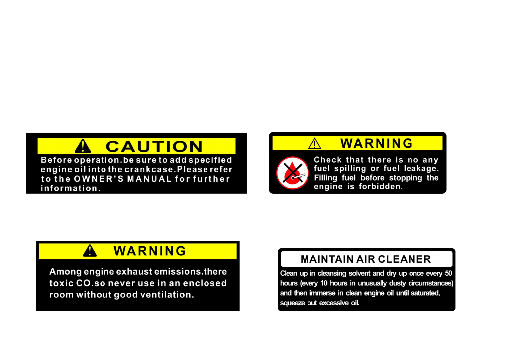
Chapter II Safety symbols
The following symbols are to remind you that if you don’t pay attention, you might be severely injured.
Please carefully read the symbols and notices about safety in the manual.
If these symbols peel off or are illegible, please contact the distributor to replace such symbols.
Figure 2-1 Figure 2-2
Figure 2-1 to be stuck on engine fuel tank Figure 2-2 to be stuck on engine fuel tank

9
Figure 2-3 Figure 2-4
Figure 2-3 to be stuck on engine fuel tank Figure 2-4 to be stuck on engine air filter
Figure 2-5 Figure 2-6
Figure 2-5 to be stuck on fender Figure 2-6 to be stuck on fender
All the safety symbols conform to GB10396.
This manual suits for next models
1
Table of contents
Other LONCIN Tiller manuals


Popular Tiller manuals by other brands


MTD
MTD OHV Series Original operating instructions

YAT
YAT YT5601-01 Assembly, Use, Maintenance Manual

Craftsman
Craftsman 917.296010 owner's manual

Troy-Bilt
Troy-Bilt OEM-290-260 Operator's manual

Scheppach
Scheppach MTP560 Translation from the original instruction manual

GARDEN WAY
GARDEN WAY 12194 owner's manual

Classen
Classen STAND-AER SA-25 Operator's manual and parts list

Craftsman
Craftsman 850 Series owner's manual

DR
DR PILOT 2 Safety & Operating Instructions

Altrad
Altrad ATIKA BH 1400 N Original instructions, safety instructions, spare parts

WIL-RICH
WIL-RICH 2500 Operator's manual

Viking
Viking HB 685 instruction manual