Long 360 Series User manual

SERVICE
MANUAL
360
.•
460 • 510
SERIES
TRACTORS
LONG
MFG.
N.C.
INC.
P.O.
Box
1139,
111
Fairview
St., Tarboro,
N.C.
27886
Tel. (919) 823-4151, Telex #510-929-o695
Form
756006
Rev.
8183

.
\'''
A SAFETY PRECAUTIONS A
AVOID ACCIDENTS
Most
accidents,
whether
they
occur
in
industry,
on
the
farm. at
home
or
on
the
highway,
are
caused
by
the
failure
of
some
indi-
vidual
to
follow
simple
and
fundamental
safety
rules
or
precau-
tions.
For
this
reason
MOST
ACCIDENTS
CAN
BE
PREVENTED
by
recognizing
the
real
cause
and
doing
something
about
it be-
fore
the
accident
occurs.
Regardless
of
the
care
used
in
the
design
and
construct1on
of
any
type
of
equipment
there
are
many
conditions
that
cannot
be
completely
safeguarded
against
without
interfering
w1th
reasonable
accessibility
and
efficient
operation.
A
careful
operator
is
the
best
insurance
against
an
accident.
The
complete
observance
of
one
simple
rule
would
prevent
many
thousand
serious
injuries
each
year.
That
rule
is:
NEVER
ATTEMPT
TO
CLEAN,
OIL
OR
ADJUST
A
MACHINE
WHILE
IT IS
IN
MOTION.
NATIONAL
SAFETY
COUNCIL
A WARNING A
On
machines
having
hydraulically,
mechanically,
and/or
cable
controlled
equipment
(such
as
fork
lifts.
combmes.
shovels,
loaders,
dozers,
scrapers,
etc.)
be
certain
the
equipment
is
lowered
to
the
ground
before
servicing,
adjusting
and/or
repairing.
If
it
is
necessary
to
have
the
hydraulically,
mechanically,
and/or
cable
controlled
equipment
partially
or
fully
raised
to
gain
access
to
certain
items,
be
sure
the
equipment
is
suitably
supported
by
means
oth8r
than
the
hydraulic
lift
cylinders,
cable
and/or
mechanical
devices
used
for
controlling
the
equipment.
A WARNING A
ALWAYS
USE
proper
tools
and
procedures
as
recommended
in
Service
and
Operator's
Manual.
ALWAYS
READ
all
Caution
and
Note
paragraphs
in
Service
and
Operator's
Manual
before
proceedmg
with
service
or
repair
work
.

A.O.
A.
I.
A.
II.
A.
Ill.
B.O.
B.l.
B.ll.
B.lll.
B.IV.
B.V.
MASTER INDEX
A.
ENGINE
Specifications • Removal • Installation
Crankcase • Cylinder Head •
011
Sump
Valves & Timing Mechanism
Crank Gear Assembly
A.IV.
A.V.
A.VI.
A.
VIII.
Fuel System
Lubrication
Cooling
Fits
& Tolerances • Torque Specifications
B.
POWER TRAIN
Description
Clutch
Transmissions
Bevel Gear & Differential
Brakes
Independent Hand Brake
B.VI.
B.
VII.
B.VIII.
B.IX.
B.X.
B.XI.
Final Drive & Rear Wheels
Power Take·Off
Front Axle and Steering
Front Drive Axle (Side Drive)
Front Drive Axle (Center Drive)
Fits
&
Tolerances·
Torque Specifications
C.
HYDRAULICS
C.O. Hydraulic
Lift
& Linkage
C.l. Power Steering
C.ll.
Fits
&
Tolerances·
Torque
Specifications
D.
ELECTRICAL SYSTEM

•
~·.
A.O.
A.l
•
A.
II.
A.
II.
A.IV.
A.V.
-
A.VI.
· A.VIII. Flta·a
r

A.
ENGINE
INDEX
A.O.
Specifications
• Removal •
Installation
Description
........................
3
Specifications
......................
4
Fault-Finding
......................
5
Removing Engine from Tractor
........
6
Disassembly and Reassembly
........
8
Installation
........................
8
A.l. Crankcase •
Cylinder
Head • Oil
Sump
Crankcase and
Cylinder
Liners
.......
11
Checking and Cleaning the Crankcase
..
11
Cylinder Liner Re-boring and
Replacement
....................
11
Cylinder Head
.....................
12
Oil Sump
.........................
14
A.ll. Valves and
Timing
Mechanism
General
..........................
15
Timing Data
.......................
15
Camshaft
.........................
15
Valves,
Guides
and Springs
..........
17
Valve Gap
Adjustment
..............
19
Tappets, Push-Rods and Rocker Arms
...
19
Timing Gear Assembly
..............
20
Tachourmeter
.....................
21
A.lll. Crank Gear
Assembly
General
..........................
22
Crankshaft
........................
22
Crankshaft Bearings
...............
25
Pistons and Rings
..................
25
Connecting
Rods
..................
27
Engine Flywheel
...................
28
A.IV. Fuel System
Air
Supply
........................
29
Fuel Supply
.......................
29
Fuel Tank
.........................
30
Fuel Priming Pump
.................
30
Fuel Filters
.......................
30
C.A.V. INJECTION PUMP
............
33
General Description
..............
33
Injection
Pump Removal
..........
33
Pump
Installation
and Timing
.......
35
Injectors
.......................
35
Starting Aid
.....................
36
A.
V.
Lubrication
General
..........................
38
Oil Pump
.........................
39
Oil
Filter
..........................
39
Low Oil Pressure Warning Light
......
39
Lube and Capacity Chart
............
41
A.VI.
Cooling
General
..........................
42
Water Pump
.......................
43
Radiator
..........................
44
Thermostat
.......................
45
Fan
..............................
46
WaterTemperature Gauge
...........
46
A.VII.
Fits
and Tolerances • Torque Speciflca·
tions
Fits
and Tolerances 360/460
.........
47
Fits
andTolerances 510
.............
50
Torque
Specifications
..............
53
Engine· 2

A.O. SPECIFICATIONS·REMOVAL·INSTALLATION
DESCRIPTION
The engine installed in the wheel tractor models
360,
460
and 510, is a high speed diesel
unit
with
four
strokes and three cylinders-inline. The
engine crankcase is a cast iron
unibloc
with dry
type replaceable cylinder liners, and
with
the
housings for the crankshaft main bearings and
valve tappets.
Helical-teeth
timing
gears, camshaft located in
the
crankcase and overhead valves; intake valves
are shielded
to
increase turbulence
of
the
aspirated air. The power train
is
driven by the
crankshaft which revolves in four thin-shell main
14709
FIG. A.0/1 Three-Quarter Right Front View
of
Engine
1. First fuel filter;
2.
Fuel Injection pump;
3.
Air
Intake manifold;
4.
Starting aid reservoir;
5.
Injec-
tor;
6.
Second fuel filter;
7.
Thermostat location;
9. Hydraulic system
oil
pump; 10. Fuel
lift
pump;
11. Electric starting
motor
bearings and includes: Light alloy pistons with
toroidal combustion chamber
built
in top, three
piston rings (two oil scrapers and one compres-
sion ring), forged steel connecting rods and
liners lubrication and a second one through the
small end for piston cooling.
Aspirated air
is
filtered through an oil bath air
cleaner.
Fuel
is
injected
directly
into the high turbulence
combustion chamber built in piston top.
Double diaphragm fuel
lift
pump, double filters
connected in series and water trap on the first
filter.
14710
'
FIG. A.0/2 Three-Quarter Left Rear View
of
Engine With Clutch
12. Exhaust manifold; 13. Engine
lifting
eye;
14. Engine
oil
filter; 15. Engine and P.T.O.
clutch
unit;
16.
011
pressure sending
unit
connection;
17. Breather pipe; 18.
011
dipstick;
19. Alternator
Engine·
3

Injection
pump
of
the
plunger
type
with
all
speed
governor and
automatic
timing
device: type
Rotary,wlth fly-weight mechanical governor.
Separate
four
hole
nozzles (360/460)
or
three hole
nozzles (510)
clamped
to
the
cylinder
head.
Forced feed
lubrication
from
camshaft
driven
gear-type
pump
with
built
in
relief
valve.
Full
flow
filter
screwed
to
the
crankcase and pro-
vided
with
an
Internal
relief
valve
which
bypasses
the
oil
flow
when
filter
is
clogged.
CIRCULATING WATER
AND
RADIATOR COOL·
lNG SYSTEM
A
centrifugal
pump,
belt-driven
by
the
crankshaft-mounted drive pulley, forces
the
coolant
flow
which
enters
the
radiator when the
temperature reaches
up
to
thermostat setting.
The cold air drawn by the fan
which
is secured
to
the
water
pump
hub,
cools
the
coolant inside the
radiator.
Direct
electric
starting
with
solenoid engage-
ment,
12
volt
motor
and starting aid
for
low
temperatures.
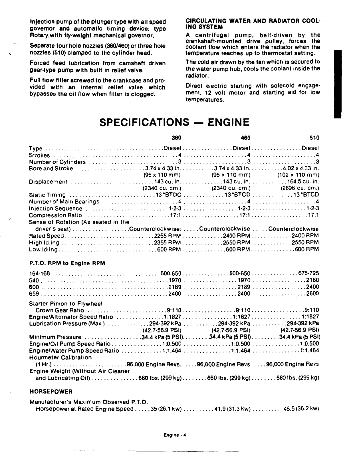
SPECIFICATIONS -ENGINE
360 460 510
Type
.....................................
Diesel
................
Diesel
................
Diesel
Strokes
.......................................
4
....................
4
....................
4
Number
of
Cylinders
............................
3
....................
3
....................
3
Bore and Stroke
......................
3.74 x
4.33
in
...........
3.74
x 4.33 in
...........
4.02 x 4.33 in.
(95
x 110 mm)
(95
x
110
mm)
(102
x
110
mm)
Displacement
..........................
143
cu. in
..............
143 cu. in
............
164.5 cu. in.
(2340 cu. em.) (2340 cu. em.)
(2696
cu. em.)
Static Timing
...........................
13°8TDC
.............
13
°8TCD
.............
13
°8TCD
Number
of
Main Bearings
........................
4
....................
4
....................
4
Injection
Sequence
..........................
1-2-3
.................
1-2·3
.................
1-2-3
Compression Ratio
...........................
17:1
..................
17:1
..................
17:1
Sense
of
Rotation (As seated in the
driver's seat)
..................
Counterclockwise:
.....
Counterclockwise
.....
Counterclockwise
Rated Speed
............................
2255
RPM
.............
2400
RPM
.............
2400
RPM
High Idling
.............................
2355
RPM
.............
2550
RPM
.............
2550
RPM
Low Idling
...............................
600
RPM
..............
600
RPM
..............
600
RPM
P.T.O. RPM
to
Engine
RPM
164-168
..................................
600-650
...............
600·650
...............
675-725
540 '
.......................................
1970
.................
1970
.................
2160
600
........................................
2189
.................
2189
.................
2400
659
........................................
2400
.................
2400
..........
-
......
2600
Starter Pinion to Flywheel
Crown Gear Ratio
.........................
9:110
.................
9:110
.................
9:110
Engine/AlternatorSpeed Ratio
...............
1:1827
....
.'
...........
1:1827
................
1:1827
Lubrication Pressure (Max.)
.............
294-392 kPa
...........
294-392 kPa
...........
294-392 kPa
(42.7-56.9 PSI) (42.7-56.9 PSI) (42.7-56.9
PSI)
Minimum
Pressure
..................
34.4 kPa
(5
PSI)
........
.34.4
kPa
(5
PSI)
.........
34.4 kPa
(5
PSI)
Engine/Oil Pump Speed Ratio
................
1:0.500
...............
1:0.500
...............
1:0.500
Engine/Water Pump Speed Ratio
.............
1:1.464
...............
1:1.464
...............
1:1.464
Hourmeter Calibration
(1
Hr.)
.......................
96,000 Engine Revs. .
...
96,000 Engine Revs
....
96,000 Engine Revs
Engine Weight (Without Air Cleaner
and Lubricating Oil)
...............
660 lbs.
(299
kg)
........
660 lbs.
(299
kg)
........
660 lbs.
(299
kg)
HORSEPOWER
Manufacturer's Maximum Observed P.T.O.
Horsepowerat Rated Engine Speed
.....
35
(26.1
kw)
..........
41.9
(31
.3
kw)
..........
48.5
(36.2
kw)
Engine- 4
-----
--------
---

FINDING THE PROBLEM IN CASE OF POOR
ENGINE PERFORMANCE
If
test
specifications
cannot be met:
1.
Check, by
excluding
one
cylinder
at a time,
that the compression pressure drop
is
cons·
tant
in order
to
ascertain the functional
effi·
ciency and
uniformity
of
nozzles
or
try
once
again using a set
of
calibrated
test
nozzles.
2. Look
for
the causes
of
poor engine perfor·
mance. Use a compression·
tester
applying
it
in succession
to
each cylinder,
to
which
the
present
test
data and procedure refer. (See
chart.)
Test the engine when temperature has reached
158°F. (70 °C.), corresponding
almost
to
the
limit
of
the
white
band
of
the panel-mounted
temperature gauge, and
stop
the engine.
1.
Remove the
injectors
from the cylinders.
2.
Install a
compression
tester in place
of
the
injector
corresponding
to
the
cylinder
to
be
tested.
3.
Hold the
injection
pump
in
"STOP"
position
and take the readings,
turning
the engine
with
the starter motor.
The pressure reading for a normally operating
engine, recorded at temperature
of
about 180
oF
(82 °C.) and at sea level (760 mm.
of
mercury), and
for
a speed
of
about 650
RPM
is
375-425
PSI
(26.4-29.9 k/cm2)
with
all
injectors
removed.
The
minimum
permissible pressure reading
for
a
worn engine
is
375
PSI
(26.4 k/cm2
).
It
must
be kept in mind that pressure
drops
of
1%
for
every 100 m. increments
of
altitude. (Ap·
proximately
320 feet.)
The maximum permissible pressure
difference
between the various cylinders is 50
PSI
(3.5
k/cm
2
).
Compression faults can be traced to: valves and
seats,
pistons
and
their
rings,
cylinder
head
gasket.
60402
FIG. A.0/3 CHECKING ENGINE COMPRESSOR
WITH TESTER
A CAUTION!
Pressure
test
data are reliable
only
if
the gauge
is
functionally
efficient
and
correctly
installed
and
if
temperature and speed requirements have
been met. Do
not
start overhauling
or
repairing
an
engine
following
a
single
low
compression
reading,
or
if
the gauge
is
not
the
one
indicated
or
if
the
test
has
not
been carried on as
specified.
Engine·
5
------

FAULT DIAGNOSIS CHART
EXCESSIVE EXHAUST
SYMPTOM CAUSE CHECK
No
fuel 1 Fuel level
2 Stop control 2 In run position and linkage free
3 Starting procedure 3 Is it correct
3115 4 Air in system 4 That system is vented and all
joints
and unions air tight
5•
5 Fuel restriction 5 Filters and pipes clear
6 Fuel contamination 6 That fuel is free
of
water, dirt, ice and wax
7 Cranking speed 7 Correct Lub, oil, Battery, starter and cable connections
8 Starting aid 8 Correct functioning, Fuel supply and electrical
connect1ons
9•
9•
9 Injection
timing
9 Pump
to
engine
timing
1lill!i!§
10•
10
Feed pump
10
Pressure
~
11•
11
Blocked return pipe
11
DPA back leak, return
to
tank and filter vents are free
12•
12•
12
Poor compression
12
Cyl. comp. Air intake clear. Injector seats. Valve
clearances & timing
14•
14•
14
Fuel atomisation
14
Injectors·
type, setting, condition, sealing and evenly
tightened down
15•
15
Fuel tank vent
15
Vent unrestricted
16•
16
Firing order
16
HP pipes
fitted
in correct order
17
HP pipe restriction
17
HP pipe bores not kinked or reduced at nipples
18•
18
HP leaks 18 HP pipe joint
tightness
19•
19
LP
leaks 19 Fuel pipes for leaks
~
20
Idling speed incorrect 20 Engine idling speed
setting
~iii§
21•
21
Max. speed incorrect
21
Engine maximum no load setting
22•
22
Accelerator linkage
22
Lever loose on pump, reaches stops. Linl(age wear.
Pedal stop setting
23
Engine mounting 23 Mountings are
tight
24
Vibration
24
Vibration not transmitted from elsewhere
25•
25
Overloading
25
Vehicle payload
26•
26
Brakes
26
Brakes not binding
27
F I pump
mounting
27
F I pump drive and
mounting
bolts
tight
28• 28•
28
F I pump 28 If
811
else
f8ils
rwmove
F I
pa.mp
Mel send for specialist check
Engine·
5A

REMOVING THE ENGINE FROM TRACTOR
Proceed
according
to
the
following
sequence:
1.
i1emove the radiator
grill
after
removing
the
•Jpper
bolts
in
either
direction,
then
discon·
nect the battery cables and remove battery.
(See Fig. A.0/4.)
2.
Drain all fuel and
close
the fuel valve. Drain
the crankcase
oil
through
the
bottom
plug
hole and
the
crankcase and
radiator
coolant
through
the
plugs
(Items 13 and 14, Fig.
A.0/5)
located
on the
left
side
of
the
engine.
3 Remove the
front
axle
with
radiator,
after
disconnecting
or
detaching:
(a)
Transmission
oil
suction
line
(Item 21,
Fig. A.0/6)
to
hydraulic
pump
and
delivery line (Item
20)
to
hydraulic
lift;
making sure
to
plug
holes
to
prevent
spill·
age
of
oil
and
contamination
of
lines.
(b)
Band clamp
securing
air
cleaner
hose
(Item
19)
to
intake
manifold
water
inlet
and
outlet
hoses
from
radiator
and,
finally, the
exhaust
muffler
(Item
11);
(c)
Steering drag
link
(Item
12)
from steering
arm (if applicable).
(d)
Remove
bolts
holding
ram
anchor
to
transmission
housing.
Lock the parking brake.
Insert
two
wooden wedge
blocks
on the axle
and
lift
tractor
with
a hydraulic
jack
or
hoist
until
free from the engine; place
shop
stands
or
wooden
blocks
under
the
transmission
case, remove the
capscrews
(Item
C2,
Fig.
A.0/5)
attaching
axle
to
oil
sump
and, finally,
·remove the front axle
assembly
cowling
and
radiator.
A CAUTION:
When using
the
axle wedges, be sure
they
fit
and
are driven in
tight.
Also, any
blocks
or
stands
us·
ed
in
splitting
the
tractor
should
be stable. The
brakes
should
be
locked
by
stepping
on
the
brake pedals and
pulling
the
parking brake back.
Be sure any
slings
or
chains
are capable
of
sup-
porting
the
portion
of
the
tractor
to
be
hoisted.
4.
Remove
the
rear hood
section
with
instru·
ment and rear panels:
(a)
The
starting
and
lighting
switch
(Item 26,
Fig. A.0/7) and
the
starting
switch
(Item
30)
and lever.
(b) Remove
the
rear hood,
instrument
panel
and rear panel
attaching
capscrews;
FIG.
A.0/4
FRONT
VIEW
OF
TRACTOR
WITHOUT BONNET.
1.
Air
cleaner clamp;
3.
Battery
ground
cable;
4. Plus terminal;
5.
Headlight
connection
cables.
(c)
Disconnect
the
connections
located
behind the
instrument
panel and
unscrew
the
tachometer flexible drive (Item
9,
Fig.
A.0/5).
5.
Remove fuel tank, as follows:
(a)
Disconnect
cable (Item
28,
Figure A·0/7)
from
the
starting
safety
switch
located
on
the
transmission
case cover.
(b)
Slacken the band clamps, then remove
suction
and return
oil
lines (Item
9,
Fig.
A.l/3) from injectors.
,(c)
Disconnect
the
fuel level
indicator
wire
with
bayonet-type
connection
located on
the fuel tank.
(d) Remove the tank strap
after
loosening
and
withdrawing
the attaching bolt.
6. Remove
the
fuel
tank
support
and
electric
control
box
mounting
as
an
assembly, as
follows:
(a)
Disconnect
the
alternator
cable (Item 8,
Fig. A.0/5) and the
two
band
clamps
(Item
7,
Fig. A.l/3)
attaching
to
it
the
intake
manifold.
(b) Remove
the
starting
motor
(Item 23, Fig.
A.0/6) cable (Item
22)
and the water
temperature gauge (Item
18)
and
low
oil
Engine·
6

FIG. A.0/5 LEFT SIDE VIEW OF ENGINE INSTALLED
c
..
Capscrews attaching engine
to
transmission case;
C2.
Capscrews attaching front axle
to
oil
sump;
7.
Crankcase breather;
8.
Alternatorcable;
9.
Tachourmeter flexible drive;
10.
Low oil pressure
sending unit;
11.
Exhaust muffler; 12. Steering drag link; 13. Crankcase water drain;
14.
Radiator
water drain cock;
15.
Radiator water
outlet
hose; 16. Alternator; 17. Belt take·up bracket
14714
FIG. A.0/6 RIGHT SIDE VIEW OF ENGINE INSTALLED
c,. Injection pump
locating
nuts;
P.
Hydraulic
lift
oil
pump; 18. Water temperature gauge cable;
19. Intake manifold;
20.
Delivery line
to
hydraulic lift;
21.
011
pump
suction
line;
22.
Electric starting
motor
cable;
23.
Electric starting motor;
24.
Steering pump
Engine·
7

FIG. A.OI7 INSTRUMENT PANEL AND
REAR
PANEL
26. Key
switch;
27.
Rear
flood
light
cable;
28. Starting safety
switch
cable; 30. Starting and
thermostart
switch
pressure
indicator
(Item 10, Fig. A.0/5)
cables.
(c) Remove
the
hand and
foot
accelerator
rods
from
the
linkage.
(d) Remove
the
attaching
capscrews
(Item
c,,
Fig. A.0/5)
to
the
transmission
case.
7.
Hook
three
chains
into
the
three
lifting
eyes
(Fig.
A.0/8)
on
the
engine
and
take
the
weight
·off
with
a
hoist.
Lift
the
engine
and
pull
it
off
forward
to
allow
the
clutch
shafts
to
clear
the
clutches.
DISASSEMBLY AND REASSEMBLY
Attach
the
engine
on
an engine
stand.
INSTALLATION
Reverse
the
removal
sequence
and
be sure
to
remember
the
following:
1.
When
attaching
the
engine
to
the
transmis-
sion
case, be sure
to
locate
the
clutch
splines
on
their
respective
gearbox and
P.T.O.
shaft
section
properly
so
to
avoid jam-
ming
or
spline
damage.
2.
Tighten
to
specified
torque
values.
,. .I
..
..
·"'~
I
..
\:.
!
,,
t
'·
\
~
'
FIG. A.0/8 REMOVING ENGINE FROM TRAC·
TOR
WITH LIFTING CHAINS
14718
FIG.
A.0/9
INSTALLING
ENGINE
ON
TURNOVER STAND
Engine·
8
/
)

---
~=----------
I I
I
-""
/ j
FIG. A.0/9A ENGINE • SECTIONAL VIEW
Engine·
9

14717
FIG. A.0/98 ENGINE· SECTIONAL VIEW
Engine·
10

'
A.l CRANKCASE-CYLINDER HEAD-OIL SUMP
For a general overall inspection
of
the crankcase
components, remove
~ngine
from tractor as in·
dicated on page
6.
CRANKCASE AND CYLINDER LINERS
The cast iron crankcase and cylinder
block
unit
construction
comprises the cylinder liner bores,
crankshaft main bearings, camshaft bearing
bores, and the valve tappet bores. Cylinder
liners,
of
the dry type, are inserted by cold press
fitting.
New liners
must
be bored
to
proper size
after
installation in engine bore. (See
"Fits
and
Tolerances-Torque Specifications-section.)
Class
identification
letters
are stamped on
the
crankcase
top
surface (Fig. A.l/1
),
in cor-
respondence ':lf each liner.
CHECKING AND CLEANING THE CRANKCASE
At overhauls check for causes of oil and water
leaks and seepage.
Proceed
as
follows:
1.
Wash the crankcase with a hot detergent and
water solution, and flush it repeatedly
with
cold water.
2.
Degrease the lubrication passages
with
a
jet
of pressurized air and solvent mixture and
remove sludge from the inside
of
passages.
3.
Check sealing
tightness
of
threaded and ex-
pansion plugs, and replace damaged ones.
4.
Check the face parallelism
of
the cylinder
head mating surface using a straight edge
and feeler gauge and,
if
necessary, reface it.
5.
To avoid fluid leaks or seepage, make sure
both crankcase and cylinder head mating
surfaces are clean, before installing the
gasket. Do not use any type
of
gasket
sealant.
14718
FIG. A.l/1 CHECKING CYLINDER LINER BORE
WITH A DIAL INDICATOR GAUGE (ARROWS IN·
DICATE CLASS OF FIT.)
CYLINDER LINER RE-BORING AND REPLACE·
MENT
Check the
liner
inside diameter by placing a dial
gauge successively on
two
axes perpendicular
to
each other (Fig. A.l/1) and take these readings
at three
different
heights (Fig. A.l/2)
to
locate
ovalization
or
excessive wear.
If
necessary, re-bore
the
liners
to
the next over·
size diameter, the measurements are listed in
the
"Engine
Fits
and Tolerances" table. If, on the
other
hand, the liners
which
require re-boring are
already oversized
of
0.0254 mm.
(0.001
in.), which
is
the maximum permissible oversize, replace
them, and bore
to
propersize.
Engine·
11

~
I
~
1
I
X
I
2
I
I
' f
-
~
FIG. A.l/2 STANDARD LINER AND CRANKCASE
BORE DIMENSIONS
a-b. Liner measure locations;
C.
Final dimen·
sion after press-fitting.
(Liners are classified dimensionally as A
or
B.
See
specification chart). ·
1,
2 and
3.
Bore
measuring planes.
360/460 510
X 98.890mm 3.893 in. 105.890mm 4.169 in.
98.940mm 3.895 in. 105.940mm 4.171 in.
y 95.000mm 3.740 in. 102.000mm 4.015 in.
95.024mm 3.741 in. 102.024mm 4.016 in.
z 99.020mm 3.898 in. 106.020mm 4.174 in.
99.050mm 3.899 in. 106.050mm
4.175in.
A ·cAUTION:
If
the dowel
with
lube
oil
flow
restriction
is
removed also, make sure
to
install
it
with
the
smallerhole toward the
cylinder
head.
CYLINDER HEAD
Special alloy cast iron
cylinder
head
with
harden·
ed valve seats and nozzle mounting holes.
To remove the cylinder head from a tractor in·
stalled engine, proceed as follows:
1.
Remove hood assembly.
2.
Drain crankcase and radiatorcoolant through
the respective
cocks
located on the engine
left
side.
3.
Loosen
the
band
clamp
which secures the
cylinder head
coolant
outlet
hose
to
the
radiator.
4.
Remove the valve cover (Item
5,
Fig. A.l/3)
backing out the capscrews (Item C.).
5.
Remove the intake manifold (Item
6)
to gain
easier access
to
the lines and tubing in·
dicated below.
6. Disconnect the nozzle pressure and return
lines (Items 8 and 9 respectively).
7. Remove rocker arms
with
shafts and sup·
ports, and the push rods.
8. Remove the thermometer bulb.
9. Unscrew the attaching capscrews from the
crankcase and
split
the head away without
wedging with tools inserted between mating
surfaces
to
avoid damage.
If
the cylinder head is removed with the nozzles
installed, care must be taken not
to
damage the
latter which project above the surface, or remove
them first
as
a precautionary measure.
FIG. A.l/3 REMOVING THE TAPPET COVER
(5)
c,. Tappet cover attaching nut;
4.
011
filler plug;
6.
Intake manifold;
7.
Alternator cable band
clamps;
8. Nozzle pressure
line
retaining
bracket;
9.
Nozzle return
oil
lines.
Engine·
12

'
FIG. A.l/4 REMOVING CYLINDER HEAD FROM
ENGINE INSTALLED ON ENGINE STAND
The
instructions
for
removing the
cylinder
head
from an engine removed from the tractor are
similar
to
the ones given previously
for
the trac·
tor
installed engine, provided
of
course that in
the former case the engine
unit
will
have
to
be
installed on the shop turnover stand. (See Fig.
A.l/4).
CHECKING THE CYLINDER HEAD
For complete inspection and checking
of
the
cylinder head,
it
is best
to
remove valves, valve
springs and nozzles and
to
clean the mating sur·
face, valve seat and passages.
Check the
cylinder
head mating plane by moving
it
overa surface plate smeared with lampblack
or
blue.
If
high spots show up, reface it.
If
valve seats are
to
be re·cut, the
cylinder
head
mating
plane can be ground
to
a depth not ex-
ceeding 0.020 in. (0.5 mm.).
In case
of
grinding, we suggest that a copper
washer
of
suitable
thickness
be placed inside
the nozzle seat
so
to
maintain the nozzle projec-
tion
above the
cylinder
head at the same value as
before; also, make sure the valve recessing from
the cylinder head plane does not exceed 0.03-
0.04 in.
(0.7
•
1.1
mm.) (Fig. A.l/5). The
height
of
a
new
cylinder
head is 3.662 in. (92 mm.).
Check the expansion
cups
and threaded plug
for
coolant
and
oil
tightness
and replace them
if
necessary.
Following
checks, Inspections, grinding, wash
cylinder
head
in
solvent
to
remGve even the
slightest
trace
of
abrasive matter.
15129
FIG. A.l/5 MEASURING NOZZLE PROJECTION
ABOVE CYLINDER HEAD PLANE(a) AND VALVE
RECESSING (b)
Nozzle projection: 0.08 • 0.10 in.
(2
•
2.5
mm.)
Valve recessing: 0.03 • 0.04 in.
(0.7
·
1.1
mm.)
15130
FIG. •A.I/6 DIMENSIONS
OF
lNTAKE AND EX·
HAUST VALVE SEATS AND OF VALVE GUIDES
IN CYLINDER HEAD
X = 13.966 mm. · .549 in.
13.983 mm. • .550 in.
(A) Intake
Valves
mm.
ln.
Dia. D
40
1.575
Dia. E 48.6 1.913
(s) Exhaust
mm.
ln.
33
1.299
41.6 1.638
Engine·
13

1"::\.
,-------.
0
,-----.
'5\
,-----.
ljj\
\:tl,
...
,
,\,;J,
'~
, \ ,' '
,'
',
, ' , \ , \
i
~
:
~
:'
~
1 I I I t I
'.
,'
\ / \ I
~---
,'0', /"'-''
/r.:\
~
______ / J
·-------
\!J .
_____
,
~
0
1~07------------------------------_J
FIG. A.l/7 CYLINDER HEAD TIGHTENING
SE·
QUENCE
(See
Torque Specification Table.)
CYLINDER HEAD AND GASKET INSTALLATION
Reverse
the
sequence
of
removal and take good
note
of
the
followina:
1.
Thoroughly clean
both
crankcase and cylin-
der head mating planes
to
remove gasket
particles
which
have remained
stuck
to
the
surfaces at removal.
2.
Do
not
apply any sealing compound
to
the
gasket, as
its
surfaces have already been
treated
with
a
suitable
adhesive compound
over the areas requiring the greatest sealing
performance:
this
will
adhere
to
the crank-
case and
cylinder
head surfaces under the
effect
of
heat as
the
engine reaches
operating temperature.
3.
Place
the
cylinder
head
with
the
crankcase
locating
dowel
fitting
in the head hole.
4.
Install the capscrews and torque them
following
the sequence illustrated in Fig.
A.l/7 and
to
the
values given in the
"Torque
Specifications"
table.
ENGINE OIL SUMP
To remove the
oil
sump
only
from a
tractor
in·
stalled engine, proceed as
follows:
1.
Drain
oil
through plug
hole
at
bottom
of
sump.
2.
Disconnect the hydraulic
lift
delivery and
return
oil
lines.
3.
Remove the
front
axle assembly as outlined
on page 108 in PowerTrain Section.
4.
Back
out
the capscrews attaching the oil
sump
to
the crankcase. Before removing
them, place a wooden
block
under the sump
to
support
it
once free.
The operation
is
easier
if
the engine is installed
on a turnover stand, as
it
will
be
sufficient
to free
the
pump
to
remove the attaching screws
to
the
crankcase.
As
to
cleaning and checking, see the
outline
reported in the preceeding
topic
and referring
to
the crankcase.
When installing the oil sump, be sure to:
1.
Apply
a
thin
coating
of
non-hardening
sealing
compound
on
both
surfaces. Install
the
end seals over
the
gaskets and make sure
the
holesare aligned.
2.
Place the
sump
and
install
all attaching
capscrews.
3.
Make sure the
oil
sump and engine bell hous-
ing
are flush
with
each other.
4.
Cross
tighten
progressively
to
the
torque
values in
the
"Torque
Specifications"
table.
Engine-
14

A.ll VALVES AND TIMING MECHANISM
GENERAL
Overhead valves are actuated by the camshaft
which
is
driven from the engine through the
tim·
ing gears. The camshaft motion
is
transmitted
to
the valves through tappets, push rods and rocker
arms (Fig. A.ll/1).
Each valve is fitted
with
one spring and one
guide, the length
of
the latter inside the cylinder
head being limited by a stop ring. The intake
valves are shielded
to
create turbulence and their
correct assembly is made fool-proof by allowing
only one possible installation position.
TIMING DATA
Valve opening and closing angles, with respect
to
crankshaft rotation, are
as
follows:
Intake Valves
Opening Advance
.............
3o before T.D.C.
Closing Retard
...............
23
o after B.D.C.
Exhaust Valves
Opening Advance
.........
48
o 30' before
B.
D.C.
Closing Retard
.................
6o afterT.D.C.
Cold Valve Gap (Intake and Exhaust) for Timing
Check
....................
0.018 in.
(0.45
mm.)
Cold Valve Service Gap (Intake and Exhaust) for
Engine
...............
Intake (0.250 mm) 0.010 in.
Exhaust (0.250 mm) 0.010 in.
Total Valve Down Stroke Inside Cylinders in the
Opening Phase
...
Exhaust (10.000 mm.) 0.394 in.
Intake (10.000 mm.) 0.394 in.
CAMSHAFT
Crankcase-mounted camshaft revolving in three
bearings
with
friction
metal
lining
and force-
fitted
in
their
respective crankcase housing
bores. The
shaft
(Item
a,
Fig. A.ll/3) Is retained
at
front
by means
of
a
stop
flange (Item
9)
and car-
ries a driving gear (Item
10)
press
fitted
hot
and
keyed
to
Its
front
end.
Remove the camshaft and
its
sleeve bearings as
follows:
1. Remove the engine according
to
the direc-
tions
outlined
on page 6 and install It on an
engine stand.
2.
Remove the
timing
gear
cover_
after removing
the following:
(a)
Hydraulic pump (Item
P,
Fig. A.lll/1).
(b) Injection Pump Drive Gear Inspection
Cover (Item
7).
(c) Remove
oil
pan and oil pump.
FIG. A.ll/1 VALVE DRIVE AND CONTROL
MECHANISM
H. Clearance between
cup
retaining cap and
locks;
Z.
0.394 ln. (10.000 mm.) Maximum valve
down
stroke exhaust;
Z.
0.3941n. (10.000 mm.)In·
take; 1. Camshaft;
2.
Tappet;
3.
Push rod;
4.
Rocker Arm;
5.
Valve
FIG. A.ll/2 TIMING DIAGRAM
Engine·
15

FIG. A.ll/3 CAMSHAFT REMOVED
6.
Oil pressure reducing hold;
7.
Oil circulation
groove;
8.
Oil
pump
driving gear; 10. Camshaft
driving
gear
a)
Removing the capscrews securing the cam·
shaft stop flange (Item
9)
to the crankcase.
(d)
V-belt (Item
6),
after loosening the front
bolt
of
the alternator.
(e)
Drive pulley (Item
5)
and
its
hub with a
puller
with
three
slots
at
120
o each.
(f) Fan and driven pulley.
Remove the end plate attaching capscrews (Item
c,,
Fig. A.ll/4) by
using
a suitable wrench through
the
two
holes machined in the gear
for
this
pur·
pose (Fig. A.ll/3). Once these operations have
been completed, and before withdrawing the
camshaft and gear unit, secure
lifters
in place
to
prevent the
tappets
from falling
into
the oil
sump. Remove
the
gear from shaft end using a
press, as the gear
is
assembled
to
a shrink
fit
following
immersion
in hot
oil
at 356°F. (180°C.)
REPLACING THE CAMSHAFT BEARINGS
In case
of
bearing replacement, we recommend
the
following
sequence:
1.
Remove
the
oil
sump and
timing
gear case,
if
necessary
to
ease the job.
2.
Use a
bushing
puller
on the front bearing
(Fig. A.ll/6) and the same puller
with
exten-
sion
for
the
intermediate one.
3.
Remove
the
rear crankcase mount.
4.
Drive
out
the
expansion plug located at the
rear sleeve bearing using a suitable bar
through
the
crankcase.
FIG. A.ll/4 SECTIONAL VIEW OF THE CAM·
SHAFT DRIVE
Ca.
Capscrews securing the gear
(1
0)
and cam·
shaft
assembly
to
the crankcase;
9.
Stop flange;
10. Driving gear
5.
Remove the rear bearing
with
the same
pullers used on front and intermediate ones.
At installation, be sure to:
1.
Measure each bushing
to
be
sure they go in·
to
the proper bore.
(See
Fig. A.ll/5).
2.
Arrange
bushings
so that lube passages are
aligned
with
the
matching
passage in the
crankcase.
3.
Drive in the intermediate bushing
with
a
bushing installation tool.
4.
Use a bushing installation tool
for
the front
and rear bushings.
5.
Line bore the bushing with a reamer
to
the
,diameter specified in Fig.•A.II/5.
6.
When
fitting
the camshaft rearmost bearing,
be sure
to
see
if
this
is in the
modified
ver-
sion; i.e.,
with
curved uppermost surface so
to
shield the expansion cup on the crankcase
from the outside;
if
otherwise,
fit
a rubber
plug with replacement inside the cup,
to
avoid ingress
of
oil in the
clutch
compart-
ment.
CAMSHAFT AND BEARING CHECKS
Measure journal and bearing wear and check ser-
vice clearance (see table
of
data). Sleeve bear-
ings are not available
with
undersized bores;
if
necessary, replace both bearings and camshaft.
Check journal alignment
to
make sure the cam-
shaft is perfectly straight.
Engine·
16
This manual suits for next models
2
Table of contents
Other Long Tractor manuals
Popular Tractor manuals by other brands

Gravely
Gravely D Instruction book and parts list

Cub Cadet
Cub Cadet 2155 Operator's manual

Husqvarna
Husqvarna TC 38 instruction manual

Kubota
Kubota ME8200DTN Workshop manual supplement

International Harvester Company
International Harvester Company TD-14A Operator's manual

Cub Cadet
Cub Cadet 8454 Operator's manual