Look Solutions Cryo-Gate User manual

1
Operating manual
aLook Solutions product
CRYO
GATE
Accessory for low fog
to be used with CO2- high pressure tank
USA

2
Set of Equipment supplied
Original operating manual, version 2/2016
– 1 Cryo-Gate
– 1 Connecting tube complete with connectors to connect the Cryo-Gate
to the CO2-tank, 5 m
– 1 mains cable 2 m Powercon True plug
– 1 Inline-Filter
– 1 Operating manual
Please check whether all the products you ordered are supplied.

3
Content
1. Introduction 4
2. Safety instructions 5
3. Description of the parts 6
4. Operating the Cryo-Gate 8
4.1 Putting into operation 8
4.2 Switching the device off 9
4.3 Changing the CO2-tank 10
4.4 Operation 10
4.4.1 Manual operation 12
4.4.2 Operting via analogue 13
4.4.3 Operating with DMX 14
4.4.4 Operating via Ethernet 15
4.4.4.1 Artnet 15
4.4.4.2 sACN 16
4.4.5 IP-Configuration 17
4.4.6 More adjustments 18
4.4.6.1 Background lighting 18
4.4.6.2 Screen saver 18
4.4.6.3 Information about the Cryo-Gate 18
4.4.6.4 Factory Reset 19
4.5 Wiring of the connectors 19
5. Specifications 20
6. Warranty conditions 21

4
1. Introduction
The Cryo-Gate is a compact device that mates up to any professional fogger. It enab-
les the user to temporarily transform their existing fogger into a low fog generator.
The Cryo-Gate sits in front of the fogger‘s nozzle. A high-pressure dip-tube siphon
CO2tank connects to the unit and allows the user to add a variable amount of CO2and
air to the fog‘s output. The result is a cold fog that stays low.
The connector to connect the delivered safety tube to the bottle has to be a
W 21.8 x 1 1/4“ right male (CGA 320 connector). If a tank with this connector cannot
be found, you have to use an adaptor.
A tube (Ø 200 mm) can be connected to the front of the Cryo-Gate to guide the fog
into the requested direction.
The tube can be around ten meters long, allowing to place the machine away from
the stage to avoid disturbing noise.
Holes at the Cryo-Gate ease mounting it to a rack or building it into a flightcase.
Please note: Only use quick disappearing fog fluid to avoid the chance that the fog
will get warm and rises.
Also cooled down fog will rise after some time!
Please read the manual carefully before starting the device to ensure a correct
operation!

5
2. Safety Instructions
A fog machine is not a toy!
• Make sure, that all persons who work with the bottle and the gas are professionals.
Incorrect use can cause the risk of suffocation!
• Carbon dioxide is not toxic but may cause asphyxiation in high concentrations.
• Carbon dioxide is heavier then air. The highest concentration is therefore at floor
level. The maximum allowed concentration is 0.5 Vol% (MAK: 5.000 ppm).
• Ensure adequate ventilation.
• Ensure all national/local regulations for handling and storage of liquid carbon dioxide
(CO2) are observed.
• Avoid dust or dirt particles inside the CO2-hose. Always ensure complete purity of all
CO2-connectors and fittings
• Extreme temperatures at the nozzle (hot/cold)! Danger of burning/frostbite.
• Occasionally very hot droplets of fluid may escape when in operation. Never aim at
persons directly and keep a minimum distance of 3 m from the nozzle.
• Never touch the nozzle when in operation. Danger of getting burnt.
• The location of the machine must be non-flammable, non-combustible and not
sensitive to heat. It must be twice as big as the machine.
• Keep a minimum distance of 60 cm to all flammable, combustible objects and objects
sensitive to heat.
• Glycol is alcohol and burns with a slightly bluish, almost invisible flame. Never point
the fog at strong sources of ignition like fire or pyrotechnic effects.
• Never open the machine and leave the machine unattended when connected to a
power supply.
• The visibility must be more than 2 m in rooms where people walk around.
• Do not swallow the fog liquid. Keep it away from children. In case of eye contact,
rinse with a lot of water. Consult a doctor should you accidentally swallow some
fluid.

6
2. Safety Instructions
Front view
1: · Fog nozzle
2: · Air vents
3: · Touchscreen
4: · Analogue in 3pin-XLR
5: · DMX512 in/out 5pin-XLR
6: · Ethernet-Connector RJ45/Ethercon
23
4
5
6
1
3. Description of the parts
• Spilled liquid or splashed liquid droplets can cause slip hazard. Mop up the fluid and
dispose of it according to regulations.
• Fog may activate smoke detectors.
Artificially-made fog can be produced in many different ways. The method used here
to produce fog, with a device which works according to the vaporizer principle, is the
most harmless one.
No case has so far been reported in which a healthy human being has been harmed
because of using our device to produce artificial fog. However, this can only be gua-
ranteed if the professional fog generators are used appropiately, i.e. at the correct
vaporization temperatures as well as with the correctly mixed fog fluid.
We, however, recommend: People with health problems or problems of the respiratory
tract or with an inclination for allergies should avoid any contact with artificially-made
fog.

7
Rear view
3. Description of the parts
7: · Power in/out for Powercon
8: · Analogue out 3pin-XLR
9: · DMX out 5pin-XLR
10: · Connector for liquid-CO2-tube
7
8
9
10
Connection to the high pressure CO2-tank with siphon tube
11
– Avoid dust or dirt particles inside the CO2-hose!
– Always ensure complete purity of all CO2-connectors and fittings!
11: · CO2-hose
12: · Inline-Filter
13: · CO2-connector Europe
14: · T-connector to connect several
CO2-tanks
15: · Valve
11
12
12
13
13
14
15 15

8
4. Operating the Cryo-Gate
4.1 Putting into operation
1. Place a fog generator behind the Cryo-Gate.
The fog nozzle of the fog generator should be placed centric and approx. 1 to 2 cm
behind the nozzle of the Cryo-Gate.
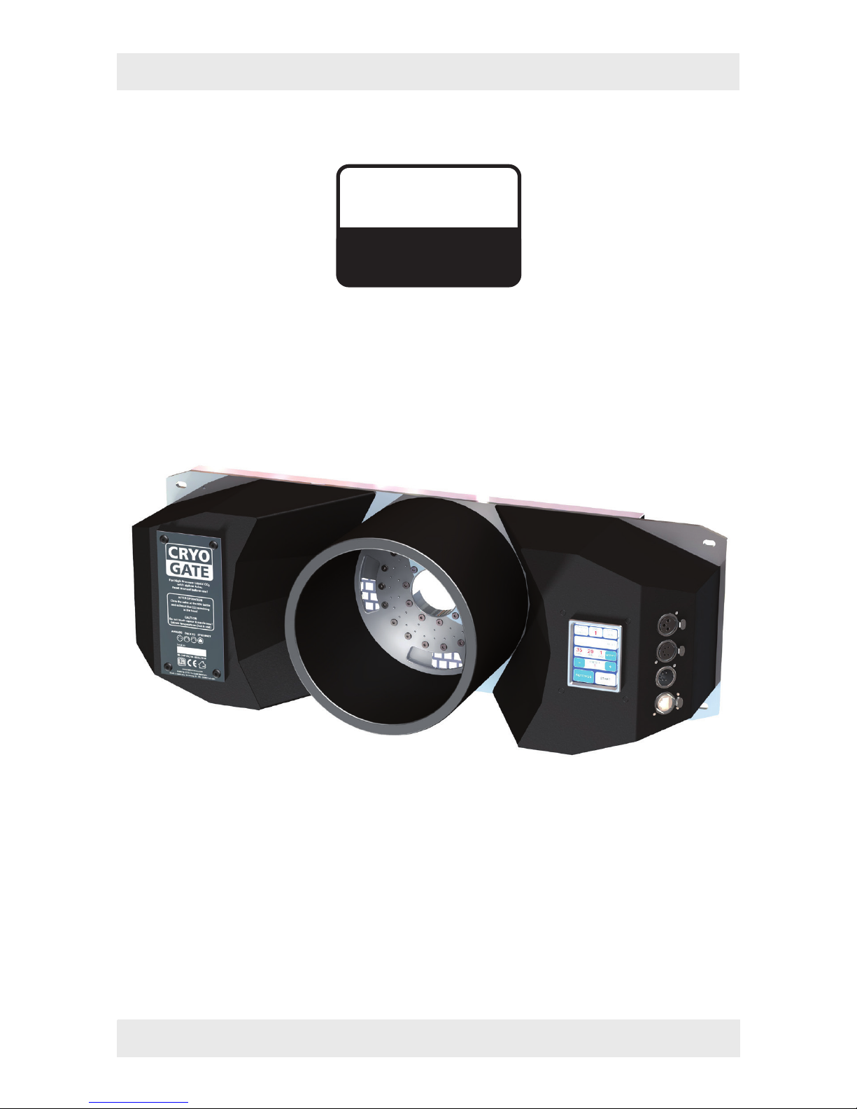
If your fog machine is equipped with a PowerCon-plug (up to max. 3 kW/1.8 kW for
USA), connect it to the Power out plug [7] at the Cryo-Gate.
If your fog machine is not equipped with a PowerCon-plug, plug the mains cable of
your machine to a normal socket.
2. Also connect the fog generator with a 5 pin-XLR-cable via DMX [5] or with a 3 pin-
XLR-cable via analogue out [4] to the Cryo-Gate/analogue in at the fog generator.
If the fog generator is connected via DMX to the Cryo-Gate, make sure the adjusted
DMX start address at the fog generator is “001“.
3. Connect the CO2-tank to the Cryo-Gate [10], using the supplied safety hose (see page
7).
Always ensure complete purity of all CO2-connectors and fittings. If you should
notice dirt particles, connect the tube to the tank, tighten the connection to make
sure that no gas can come out, and open the valve at the bottle for a few moments.
CO2comes out at the end of the hose that has not been connected yet. Close the
valve properly and connect the other end of the tube to the Cryo-Gate [10].
Tighten both connections properly to make sure that no gas can come out. Open
the valve at the tank completely [15].
4. Connect the supplied PowerCon mains cable to the jack [7] at the Cryo-Gate. Turn
the plug until it is locked. Plug the power plug to a socket.
To use your fog generator in the right way, read the operating manual of the fog
machine.
After the fog generator has heated up completely, you can start the Cryo-Gate.
A ducting hose of 20 cm Ø can be connected to the front of the Cryo-Gate.

9
4.2 Switching the device off
– Close the valve at the CO2-tank [15]. Make sure the valve is really completely closed.
Release the remaining CO2off the hose as follows:
Control via DMX:
The Cryo-Gate uses four channels at the DMX-desk: channel 1 = pump, channel 2 =
air, channel 3 = cooling/CO2 , channel 4 = fan
Put the fader for the CO2to 100% and wait until the CO2has been disappeared.
Control via Ethernet:
If the Cryo-Gate is controlled via Ethernet, tell the Software to put the channel for
the CO2to 100%.
If the Ethernet-packages will be sent from a control desk, put the fader for the CO2
to 100%.
Control via analogue:
If the machine will be controlled via analogue, adjust the analogue remote in a way
that the CO2will be released. Caution: Due to the selected Presets the fog generator
may start fogging!
To prevent this disconnect the 3pin XLR-plug of the XLR-remote from the analogue
in and do the adjustments directly at the Cryo-Gate.
Manual adjustments at the Touchscreen:
Press MODIFY at the main screen (Fig. 1, see next page). The screen switches to
MANUAL MODE (Fig. 4). Adjust a CO2 value higher than 0 with the +/- button (line
4) and press START CO2(line 4).
The internal valves opens and the CO2can exhaust.
To switch off your fog generator read the manual of the fog machine.
As soon as the CO2is completely exhausted you can disconnect the Cryo-Gate from
the mains.
4. Operating the Cryo-Gate

10
4.3 Changing the CO2-tank
Important:
Before you disconnect the hose, the CO2in the hose must ALWAYS be removed!
Please see chapter 4.2 how to do this.
– Make sure that the valve at the tank is completely closed and no CO2remains in the
hose.
– Disconnect the hose from the CO2-tank and connect it to a new tank.
Always ensure complete purity of all CO2-connectors and fittings. If you should
notice dirt particles, connect the hose to the tank, tighten the connection to make
sure that no gas can come out, and open the valve at the tank for a few moments.
CO2comes out at the end of the hose that has not been connected yet. Close the
valve properly and connect the other end of the hose to the Cryo-Gate [10].
Tighten both connections properly to make sure that no gas can come out. Open
the valve at the tank completely [15].
– Tighten both connections and open the valve at the tank completely [15].
4.4 Operation
You have several choices to control the Cryo-Gate: manual, analogue, via DMX or
Ethernet.
The following control hierarchy is valid:
1. Manual operation - will be overwritten with all other controls
2. Operation via analogue
3. Operation via DMX
4. Operation via Ethernet, overwrites everything else
The chosen/active function will be highlighted at the Touchscreen in cyan.
4. Operating the Cryo-Gate

11
After starting the Cryo-Gate the display shows the main screen (Fig. 1).
First line from left to right:
– Button ANALOG: shows the adjusted mode and the voltage. - See point 4.4.2
– Button DMX: shows whether DMX is active and the adjusted DMX-address. - See
point 4.4.3
– Button ETH: shows the selected Ethernet protocol and whether the machine is con-
trolled via Ethernet. - See point 4.4.4
Second line: shows the current value of how much CO2 has already been used. This
value can be reset by pressing RESET, for example if a new tank has been connected.
This value is only roughly measured and does not show the exact usage.
Third line: Actual values for fog (pump), air and CO2. The values can be adjusted after
pressing MODIFY. - See point 4.4.1
More air => higher output speed, higher fog level/carpet
More fog (thus more output/higher pump level) => more low fog - more CO2is needed.
Fourth line: Adjusting a Preset. - See point 4.4.1
Fifth line: SETTINGS => change to Settings 1, START => manual start of the fogging
process.
Fig. 1 Main screen Fig. 2 Settings 1 Fig. 3 Settings 2
4. Operating the Cryo-Gate

12
4. Operating the Cryo-Gate
4.4.1 Manual operation
There are two ways of manual operating: Choosing a preset or adjusting manual
values directly at the Touchscreen.
a) Selecting one of six Presets:
A preset is a specification. Three fixed presets are available, three can be adjusted
and saved individually.
The following fixed presets are available:
(1) Fog: 35, Air: 20, CO2: 1 =>
~
150 m², 10 cm high in 1 min.
(2) Fog: 45, Air: 30, CO2: 2 =>
~
150 m², 15 cm high in 1 min.
(3) Fog: 50, Air: 30, CO2: 3 =>
~
150 m², 20 cm high in 30 sec.
To choose a fixed preset:
– Press PLUS or MINUS (line 4) at the main screen (Fig. 1) until the requested preset
appears.
– Press START to start the fogging process.
The screen now changes to MANUAL MODE (Fig. 4) (where also the values for the
individual presets can be changed), now showing STOP instead of START because the
fogging process has already been started.You can stop the fogging process by pressing
STOP ALL.
Fig. 4 Manual Mode Fig. 5 Save Manual Setting
To save an individual preset:
– Press MODIFY (line 3) at the main screen (Fig. 1) and adjust the requested values
for fog, air and CO2at the currently displayed MANUAL MODE-screen (Fig. 4), using
the PLUS or MINUS-buttons.

13
4. Operating the Cryo-Gate
– Press BACK to return to the main screen.
– Press SETTINGS and at the displayed screen (Fig. 2) SAVE MANUAL SETTING,to get
to the SAVE MANUAL SETTING screen (Fig. 5).
– Select the number of the preset, where you wanted to save the adjusted values and
press SAVE.
If you only press BACK, you can return to the main screen without saving the values.
b) Using individual values:
– Press MODIFY at the main screen. The screen switches to Manual Mode (Fig. 4).
– Adjust the requested values for fog, air and CO2, using the PLUS or MINUS-buttons.
– Press START ALL to start all parameters at once, and STOP ALL, to stop all parameters.
If you only press START FOG, the fogging process will be started, but not air and CO2
(same for START AIR or START CO2, whereas START AIR without fog or CO2makes
no sense!).
The selected button changes its colour to cyan.
You can return to the main screen, pressing BACK.
4.4.2 Operating via analogue
Input voltage between 0 and 10 V. If the voltage is higher than 1 V, the machine will
be controlled via analogue, provided that neither DMX nor Ethernet is active.
To adjust the analogue in, press the ANALOG-Button
at the main screen (Fig. 1, line 1) or press SETTINGS and
at the following screen (Fig. 2) ANALOG.
Adjoining screen (Fig. 6) displays.
Select one of two modes:
1. DIRECT (line 2) for e. g. Look XLR-remote:
One Preset is active for an input voltage between 1
and 5 V, a second one for 5 to 9 V.
1 - 5 V correspond to the first half of the rotary knob
at the XLR-remote, 5 - 9 V to the second half.
– Select 1-5V PRESET and adjust the requested preset
with PLUS and MINUS (line 4). Then switch to 5-9V
PRESET and select this one as well.
2. LATCHED (line 3): Switching the preset on and off with a short voltage impulse e.g.
with a push-button or a radio remote.
– Select the requested preset with PLUS and MINUS (line 4).
Fig. 6 Select Analog Mode

14
4. Operating the Cryo-Gate
Save your adjustments (Direct or Latched) with ANALOG SAVE. If you press BACK,
you will get back to Settings or the main screen without saving the values.
Connect your cable or radio remote to the “analogue in“ at the Cryo-Gate. The
ANALOG-Button (Fig. 1, line 1) at the main screen shows the voltage and the selected
mode (DIRECT or LATCHED). Also the changed colour of the button (cyan) shows that
the analogue mode is now active.
Please note: If the machine has been started in the LATCHED-mode, it must be
stopped in the same mode. Switching into a different mode is actually not possible.
4.4.3 Operating via DMX in
Press the DMX-Button at the main screen (Fig. 1, line 1) or press SETTINGS –> DMX.
The adjoining screen (Fig. 7) appears.
Here you can type in the DMX-address.
Save the address with DMX-ADDRESS SAVE. Press
BACK to get back to the previous screen without saving
the address.
The Cryo-Gate needs four channels on the control desk:
1. Fog => goes to the connected fog machine and ope-
rates the pump.
2. Air => controls the air regulation.
3. CO2=> regulates the CO2in four divisions:
CO2usage DMX value
0 kg 0 - 64
1 kg 65 - 129
2 kg 130 - 194
3 kg 195 - 255
4. Fan => will be passed to the fog machine connected via DMX.
Connect the Cryo-Gate to your DMX-desk and make the desired adjustments with
the faders.
Fig. 7

15
4. Operating the Cryo-Gate
4.4.4 Operating via Ethernet
Press ETH at the main screen (Fig. 1, line 1) or select SETTINGS –> PROTOCOL. Screen
(Fig. 8/10) appears.
4.4.4.1 Artnet
Select ARTNET (Fig. 8, line 3). The button will change its colour to cyan, showing that
Artnet is activated.
Fig. 8 Screen with activated
ARTNET-Button
Fig. 9 Screen to configure
ARTNET
You can adjust the Net, Subnet and the Universe.
– Therefore press the MODIFY-button (Fig. 8, line 2). The screen shown on the right
(Fig. 9) appears.
Corresponding to the standards for DMX and ARTNET, a Universe consists of 512
DMX-channels. A Subnet contains 16 Universes and a Net 16 Subnets. There are 128 Nets.
– Select NET,SUBNET or UNIVERSE (Fig. 9, line 1), to change the respective value.
Press CE and type in the new value.
– Pressing ARTNET CONFIG SAVE saves the values, BACK switches back to the previous
screen (Fig. 8) without saving the value.
– Press PROTOCOL SAVE (Fig. 8, line 4) to save the ARTNET adjustments.
If you press BACK, you will get back to Settings or the main screen without saving
the values.

16
4.4.4.2 sACN
Press sACN (Fig. 8, line 3). The button changes its colour to cyan, showing its active
mode.
Fig. 10 Screen with activated
sACN-Button
Fig. 11 Screen to configure sACN
You can adjust the Universe.
– Press MODIFY (Fig. 10, line 2). The screen on the right appears (Fig. 11).
Corresponding to the standards for DMX and sACN a Universe consists of 512 DMX-
channels. In sACN there are Universes between 1 and 63999.
– Press CE (Fig. 11, line 2) and type in the value for the selected Universe.
– sACN UNIVERSE SAVE saves the value, BACK switches back to the previous screen
(Fig. 8) without saving the value.
– Now press PROTOCOL SAVE (Fig. 10, line 4) to save your sACN adjustments.
If you press BACK, you will get back to Settings or the main screen without saving
the value.
Make sure that the Cryo-Gate has a valid network address and a correct subnet mask.
You can check and change this by pressing SETTINGS –> IP-CONFIG (see point 4.4.5).
4. Operating the Cryo-Gate

17
4. Operating the Cryo-Gate
4.4.5 IP Configuration
To adjust the IP-address and the Subnet mask for your network, press SETTINGS at
the main screen and in the following Settings 1-screen IP-CONFIG (Fig. 2, line 4).
Fig. 12 IP-Configuration
screen, STATIC active
Fig. 13 Screen to adjust the IP-
address and Subnet mask
First select whether you want to use a static network address or a dynamic one (DHCP)
by pressing STATIC or DHCP (Fig. 12, line 4).
If you select DHCP,
the Cryo-Gate gets an IP-address and a subnet mask from a DHCP-Server or Router
in your network.
If you select STATIC,
you can type in the IP-address and the subnet mask in the following screen (Fig. 13).
Ask your network administrator if necessary.
– Press CE and type in the address. Save the address with IP ADDRESS SAVE respec-
tively SUBNET MASK SAVE (Fig. 13, line 5), press BACK to get to the previous screen
without saving the values.
For networks, where the IP-address and the subnet mask shall be used with the
ARTNET-standard, press STATIC and then ARTNET (both Fig. 12, line 4).
The IP-address will then be generated from the invariable MAC-address of the Cryo-
Gate and an OEM-Code. The subnet mask will be automatically set to 255.0.0.0.

18
4. Operating the Cryo-Gate
4.4.6 More adjustments
You can adjust the brightness of the background lighting.
– Press SETTINGS at the main screen, in the following
„Settings 1“-screen NEXT and in the „Settings 2“-screen
(Fig. 3, line 2) BRIGHTNESS.
– Press PLUS or MINUS to change the value.
– Save the value with BRIGHT SAVE.
Press BACK to get to the previous screen without saving
the value.
4.4.6.1 Background lighting
Fig. 14
Adjusts the time until the Screensaver appears.
– Press SETTINGS at the main screen, at the following
„Settings 1“-screen NEXT and at the „Settings 2“-screen
(Fig. 3, line 2) SCREENSAVER.
– Press PLUS or MINUS to change the value.
– Save the value with SAVE.
Press BACK to get to the previous screen without saving
the value.
4.4.6.2 Screensaver
Fig. 15
Fig. 16
Information about the Cryo-Gate
– Press SETTINGS at the main screen, at the following
„Settings 1“-screen NEXT and at the „Settings 2“-screen
(Fig. 3, line 2) INFO.
Press BACK to get to the previous screen.
FIRMWARE UPDATE starts an update of the software.
Therefore an additional programm as well as a Computer
and a network connection between PC and Cryo-Gate is
needed. More info on request.
4.4.6.3 Machine information

19
4. Operating the Cryo-Gate
Fig. 17
Here you can switch back to the default settings.
– Press SETTINGS at the main screen, in the following
„Settings 1“-screen NEXT and in the „Settings 2“-screen
(Fig. 3, line 2) FACTORY RESET.
– Press RESET only when you are sure that you would like
to return to the factory settings.
Press BACK to get to the previous screen without starting
the reset.
4.4.6.4 Factory Reset
4.5 Wiring of the connectors
5-pin XLR (DMX):
Pin 1 = Ground, Pin 2 = DMX –, Pin 3 = DMX +, Pin 4 u. 5 = nc
3-pin XLR (analog):
Pin 1 = Ground, Pin 2 = 0-10 V + DC in, Pin 3 = 12 V + DC out, max. 50 mA

20
5. Cleaning, Care and Maintenance
– Avoid dust or dirt particles inside the CO2-tube.
– Always ensure complete purity of all CO2-connectors and fittings.
– Exhaust fittings and connecting tube with CO2before connecting to the Cryo-Gate.
– Take care that the connected fog machine can not get overheated.
– Wipe up spilled fluid immediately. Moisture - also fluid - can destroy the electric parts
of the machine.
– If the Cryo-Gate is been used with a tube, there will be some residues in the tube
and also the machine after a while.
Please disconnect the tube from the duct adaptor from time to time and wipe the
inside with an absorbant cloth while the machine is disconnected from the mains.
– If the Cryo-Gate is used for a fixed installation, make 100% sure that permanent
fog-free air supply for the unit is guaranteed. Cooling air with too high fog concent-
ration (very often in Clubs or Discos) can condense inside the connected fog machine
and cause moisture damage.
– For cleaning the surface of the device use a suitable, solvent-free cleaner.
Other manuals for Cryo-Gate
1
Table of contents
Other Look Solutions Dj Equipment manuals