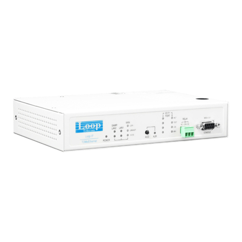
Loop Telecom Loop-IP6704A User manual

Loop Telecommunication International, Inc.
6F, Number 8, Hsin Ann Rd., Hsinchu Science Park,
Hsinchu, 300092 Taiwan
Tel: +886-3-5787696
Fax: +886-3-5646272
Loop-IP6704A
TDMoEthernet
User’s Manual

2020 Loop Telecommunication International, Inc. All rights reserved.
Version 10 June, 2020

Loop Telecommunication International, Inc.
i
IP6704A
User’s Manual
Disclaimers
I. Manufacturer assumes no responsibility for any damage or loss resulting from the use
of this manual.
II. Manufacturer assumes no responsibility for any loss or claims by third parties that may
arise through the use of this product.
III. Manufacturer assumes no responsibility for any damage or loss caused by incorrect use
of this product.
IV. The contents of this manual are subject to change without prior notice due to
engineering improvements.
V. No part of this manual may be reproduced in any form without the express written
consent of the Manufacturer.
VI. Sample displays shown in this manual may differ from the actual displays.
VII. Information in this manual may differ from software information due to firmware
changes.
VIII. All brands and product names are trademarks or registered trademarks of their
respective holders.

Loop Telecommunication International, Inc.
ii
IP6704A
User’s Manual
DE
Bitte führen Sie das Gerät am Ende seinerLewbensdauer den zue Verfügung
stehended Rückgabeund Sammelsystemen zu.
GB
At the end of the product's useful life, please dispose of it at appropriate collection
points provided in y
our country
FR
Une fois le produit en fin devie, veuillez le déposer dans un point de recyclage
approprié.
ES
Para preservar el medio ambiente, al final de la vida útil de su producto,
depositelo en los laguares destinado a ello de acuerdo con la legislación vigente.
PT
No final de vida útil do producto, por favor coloque no ponto de recolha
apropriado.
IT
I Onde tutelare l'ambiente, non buttate l'apparecchio trai i normali rifiuti al termine
della sua vita utile, ma portatelo presso i punti di raccolta specifici per questi
rifiuti previsti dalla normativa vigente.
NL
Wij raden u aan het apparant aan het einde van zijn nuttige levensduur, niet bij
hey gewone huisafval te deponeren, maar op de dearvoor bestemde adressen.
DK
Når produktet er udtjent, bor det børtskaffes via de sæ rlige indsamlingssteder i
landet.
NO
Ved slutten av produktets levetid bør det avhendes på en kommunal miljøstasjon
eller leveres til en elektroforhandler.
SW
Lämna vänligen in produkten på lämplig återvinningsstation när den är förbrukad.
SU
Hävitä tuote käytöiän päättyessä viemällä se asianmukaiseen keräyspisteeseen.
PL
Gdy produkt nie nadaje sie juz do dalszego uzytku, nalezy zostawic go w jednym
ze specjalnych punktów zajmujacych sie zbiórka zuzytych producktów w
wybranych miejscach na terenie kraju.
CZ
Po skončení jeho životnosti odložte prosím výrobek na přislušném sbĕrném
místé zřízeném dle předpisů ve vaší zemi.
SK
Po skončení jeho životnosti odovzdajte prosím zariadenie na príslušnom
zbernom mieste podía platných miestnych predpisov a noriem.
SLO
Ko se izdelku izteče življenska doba, ga odnesite na ustrezno zbirno mesto
oziroma ga odvrzite v skladu z veljavnimi predpisi.
GR
Στο Тέλος тης λειτουργικής Ζωής του προϊόντος παρακαλώ
Πετξτε το στα ειōικά σημεία που Παρέχονται οτη χωρα σας.
PRC
當產品使用壽命結束,請在你的國家所提供的適當地點做好回收處理

Loop Telecommunication International, Inc.
iii
IP6704A
User’s Manual
CAUTION:
Only qualified service personnel shall install and maintain the system.
This equipment must be connected to an earth socket-outlet, which has a permanent
connection to protective earth with a cross-sectional area of not less than 2.5 mm2.
Ensure protective earthing is connected before installing/uninstalling telephone
wires.
Never install telephone wiring during a lightning storm.
Never install telephone jacks in wet locations unless the jack is specifically designed
for wet locations.
Never touch uninsulated telephone wires or terminals unless the telephone line has
been disconnected at the network interface.
Use caution when installing or modifying telephone lines.
Précautions :
Seul le personnel qualifié peut installer et entretenir le matériel.
L’équipement doit être connecté à la prise de terre, qui doit avoir une connexion
permanente à la terre de protection avec une section de fil supérieure à 2.5 mm2.
S’assurer que la terre de protection est branché lors de l’installation ou
désinstallation des fils téléphoniques.
Ne jamais installer les fils du téléphone pendant un orage.
Ne jamais installer la prise téléphonique dans un endroit humide sans prendre la
précaution que cette prise téléphonique soit prévu pour un environnement humide.
Ne jamais toucher les fils téléphoniques dénudés sans que la prise téléphonique soit
débranché du réseau.
Prendre toutes les précautions d'usages pendant l'installation ou les modifications
de la ligne téléphonique.

Loop Telecommunication International, Inc.
iv
IP6704A
User’s Manual
Table of Content
CAUTION:......................................................................................................................................III
PRÉCAUTIONS :...........................................................................................................................III
1. PRODUCT DESCRIPTION.................................................................................................15
1.1. Description................................................................................................................15
1.2. Features....................................................................................................................15
1.3. Applications ..............................................................................................................17
1.4. Specifications ...........................................................................................................18
SERIAL TRIBUTARY INTERFACE .............................................................................................18
MANAGEMENT AND ADMINISTRATION ....................................................................................4
2. INSTALLATION.....................................................................................................................6
2.1. Site Selection..............................................................................................................6
2.2. Mechanical Installation...............................................................................................6
2.3. Pin Assignment Information.......................................................................................8
2.4. Default Setting..........................................................................................................16
2.5. Cold-swappable steps..............................................................................................17
2.5.1. Power off...........................................................................................................17
2.5.2. Open the case ..................................................................................................17
2.5.3. Remove the tributary module...........................................................................17
2.5.4. Install the tributary module...............................................................................19
2.5.5. Close the case..................................................................................................20
2.5.6. Power on...........................................................................................................20
3. OPERATION........................................................................................................................21
3.1. Power On..................................................................................................................21
3.2. Self-Test ...................................................................................................................21
3.3. Return to Default......................................................................................................21
3.4. Using Terminal .........................................................................................................21
3.5. System Configuration...............................................................................................22
3.5.1. Console Port.....................................................................................................22
3.6. Alarm ........................................................................................................................22
3.7. Report.......................................................................................................................23
3.8. LED...........................................................................................................................23
3.9. Management Port (Ethernet Port)............................................................................28
3.10. User Data Port (Ethernet)........................................................................................28
4. MAINTENANCE ..................................................................................................................29
4.1. Self-Test ...................................................................................................................29
4.2. Near End Loopback..................................................................................................29

Loop Telecommunication International, Inc.
v
IP6704A
User’s Manual
4.2.1. E1/T1 Line Loopback........................................................................................29
4.2.2. LS-Optical Fiber Line Loopback.......................................................................30
5. TERMINAL OPERATION....................................................................................................31
5.1. Log on.......................................................................................................................34
5.2. System Setup...........................................................................................................35
5.2.1. Config Setup.....................................................................................................36
5.2.2. SNMP Setup.....................................................................................................37
5.2.2.1. SNMP System Setup.............................................................................37
5.2.2.2. V1: Trap Setup.......................................................................................38
5.2.2.3. V3: User-Based Security Model Setup .................................................38
5.2.2.4. V3: View-Based Access Control Model Setup 1...................................39
5.2.2.5. V3: View-Based Access Control Model Setup 2...................................39
5.2.2.6. V3: Target & Notify Setup......................................................................40
5.2.3. Switch Setup.....................................................................................................40
5.2.3.1. RSTP Setup...........................................................................................41
5.2.3.2. QOS Setup.............................................................................................44
5.2.3.3. Vlan Setup .............................................................................................48
5.2.3.4. Port Speed Setup ..................................................................................50
5.2.4. Password Setup................................................................................................51
5.2.5. Static Route Setup............................................................................................52
5.2.6. SSH Setup........................................................................................................53
5.2.7. RADIUS Setup..................................................................................................54
5.3. Bundle Setup............................................................................................................54
5.3.1. Bundle IP Setup................................................................................................55
5.3.2. TimeSlot to Bundle Setup.................................................................................55
5.3.3. Bundle Link Setup ............................................................................................56
5.3.4. ACR TimeStamp Setup....................................................................................59
5.4. Firmware Transfer....................................................................................................59
5.4.1. Download Firmware..........................................................................................60
5.4.2. Download Boot Strapper..................................................................................60
5.4.3. Download Configuration...................................................................................61
5.4.4. Upload Configuration........................................................................................61
5.4.5. Boot Bank Change ...........................................................................................62
5.5. Clock Source Setup..................................................................................................62
5.5.1. Clock Source Setup..........................................................................................63
5.5.2. SyncE Clock Setup...........................................................................................64
5.6. System Alarm Setup ................................................................................................64
5.7. SNTP Setup..............................................................................................................65

Loop Telecommunication International, Inc.
vi
IP6704A
User’s Manual
5.8. ALS/APSD Setup .....................................................................................................66
5.9. Store/Retrieve Configuration....................................................................................66
5.10. System Display.........................................................................................................67
5.10.1. Config Display ................................................................................................67
5.10.2. SNMP Display ................................................................................................68
5.10.3. System Info Display........................................................................................68
5.10.4. Switch Display ................................................................................................69
5.10.4.1. RSTP Display ......................................................................................69
5.10.4.2. QOS Display........................................................................................70
5.10.4.3. VLAN Display.......................................................................................74
5.10.4.4. Port Speed Display..............................................................................75
5.10.4.5. Port Statistics.......................................................................................76
5.10.4.6. MAC Table Display..............................................................................76
5.10.5. Static Route Display.......................................................................................77
5.11. Bundle Display .........................................................................................................77
5.11.1. Bundle IP Display...........................................................................................78
5.11.2. DS0 TSlot to Bundle Display..........................................................................78
5.11.3. Bundle Link Display........................................................................................79
5.11.4. Bundle Summary............................................................................................80
5.11.5. Bundle Status.................................................................................................80
5.11.6. Bundle ARP Status Display............................................................................81
5.11.7. Bundle PING Status Display..........................................................................82
5.11.8. IP Conflict .......................................................................................................83
5.12. Clock Source Display...............................................................................................84
5.12.1. Clock Source Display.....................................................................................84
5.12.2. SyncE Clock Display......................................................................................85
5.13. Alarm Queue Summary............................................................................................86
5.14. Currently-Active Alarm Summary ............................................................................86
5.15. SFP Status ...............................................................................................................87
5.16. Port Display..............................................................................................................87
5.17. E1/T1 Sub-Menu......................................................................................................88
5.17.1. E1 Sub-Menu..................................................................................................88
5.17.1.1. Port Setup............................................................................................88
5.17.1.2. Port Loopback Test .............................................................................89
5.17.1.3. Clear Performance Data......................................................................89
5.17.1.4. Port Alarm Setup.................................................................................90
5.17.1.5. Clear Alarm History .............................................................................91
5.17.1.6. Bert Test ..............................................................................................91

Loop Telecommunication International, Inc.
vii
IP6704A
User’s Manual
5.17.1.7. Port 1-Hour Perf. Report .....................................................................92
5.17.1.8. Port 24-Hour Perf. Report...................................................................93
5.17.1.9. Port Line Availability............................................................................94
5.17.1.10. Port Configuration..............................................................................95
5.17.1.11. Port Status.........................................................................................95
5.17.1.12. Port Alarm History .............................................................................96
5.17.2. T1 Sub-Menu..................................................................................................96
5.17.2.1. Port Setup............................................................................................97
5.17.2.2. Port Loopback Test .............................................................................98
5.17.2.3. Clear Performance Data......................................................................98
5.17.2.4. Port Alarm Setup.................................................................................99
5.17.2.5. Clear Alarm History ...........................................................................100
5.17.2.6. Bert Test ............................................................................................100
5.17.2.7. Port 1-Hour Perf. Report ...................................................................101
5.17.2.8. Port 24-Hour Perf. Report.................................................................102
5.17.2.9. Port Line Availability..........................................................................103
5.17.2.10. Port Configuration............................................................................104
5.17.2.11. Port Status.......................................................................................104
5.17.2.12. Port Alarm History ...........................................................................105
5.18. Daughter Card Sub-Menu......................................................................................106
5.18.1. Quad E&M Voice Card.................................................................................106
5.19. Setup ......................................................................................................................107
5.19.1. Card Default Settings...................................................................................107
5.19.2. Card Config Setup........................................................................................107
Card Config Setup, TX Only .................................................................................108
5.19.3. Card Test......................................................................................................109
Card Test, TX Only................................................................................................109
5.20. Display....................................................................................................................110
5.20.1. Display Card Configuration..........................................................................110
5.20.2. Display Card Configuration, TX Only...........................................................110
5.20.3. Card Status...................................................................................................111
5.20.3.1. Card Status, TX Only ........................................................................111
5.21. MISC.......................................................................................................................112
5.21.1. Load Default Config......................................................................................112
5.21.2. E&M FPGA Reset.........................................................................................113
5.21.3. X21................................................................................................................113
5.21.3.1. Port Loopback Setup.........................................................................114
5.21.3.2. Port Alarm Setup...............................................................................114

Loop Telecommunication International, Inc.
viii
IP6704A
User’s Manual
5.21.3.3. Port System Setup.............................................................................115
5.21.3.4. Port Clear Alarm Queue & History Setup .........................................115
5.21.3.5. File Transfer.......................................................................................115
5.21.4. RS232...........................................................................................................116
5.21.4.1. Port Loopback Setup.........................................................................116
5.21.4.2. Port Alarm Setup ...............................................................................117
5.21.4.3. Port System Setup.............................................................................117
5.21.4.4. Port Clear Alarm Queue & History Setup .........................................117
5.21.4.5. Port Alarm History .............................................................................118
5.21.4.6. Port Status.........................................................................................118
5.21.4.7. Port Alarm Queue..............................................................................118
5.21.5. Single E1(FE1).............................................................................................119
5.21.5.1. Unit 1-Hour Performance Report......................................................119
5.21.5.2. Unit 24-Hour Performance Report....................................................120
5.21.5.3. Unit Line Availability ..........................................................................121
5.21.5.4. Unit Configuration..............................................................................121
5.21.5.5. Port Status.........................................................................................122
5.21.5.6. Port Alarm History .............................................................................122
5.21.5.7. Port Alarm Queue..............................................................................123
5.21.5.8. Port Loopback Test ...........................................................................123
5.21.5.9. Port System Setup.............................................................................124
5.21.5.10. Port Clear Performance Data..........................................................124
5.21.5.11. Port Alarm Setup.............................................................................125
5.21.5.12. Port Clear Alarm Queue & History..................................................125
5.21.5.13. Download Firmware ........................................................................126
5.21.5.14. Unit Reset........................................................................................126
5.21.6. Single T1(FT1)..............................................................................................127
5.21.6.1. Unit 1-Hour Performance Report......................................................127
5.21.6.2. Unit 24-Hour Performance Report....................................................128
5.21.6.3. Unit Line Availability ..........................................................................129
5.21.6.4. Unit Configuration..............................................................................130
5.21.6.5. Port Status.........................................................................................130
5.21.6.6. Port Alarm History .............................................................................130
5.21.6.7. Port Alarm Queue..............................................................................131
5.21.6.8. Port Loopback Test ...........................................................................131
5.21.6.9. Port System Setup.............................................................................131
5.21.6.10. Port Clear Performance Data..........................................................132
5.21.6.11. Port Alarm Setup.............................................................................133

Loop Telecommunication International, Inc.
ix
IP6704A
User’s Manual
5.21.6.12. Port Clear Alarm Queue & History..................................................133
5.21.6.13. Download Firmware ........................................................................134
5.21.7. QFXS ............................................................................................................134
5.21.7.1. Card Setup.........................................................................................134
5.21.7.2. Card Diagnostic.................................................................................135
5.21.7.3. Download Firmware...........................................................................135
5.21.7.4. Display Card Config...........................................................................135
5.21.7.5. Card Status........................................................................................136
5.21.8. QFXO............................................................................................................136
5.21.8.1. Set QFXO Card Config......................................................................137
5.21.9. V.35...............................................................................................................137
5.21.9.1. Port Loopback Setup.........................................................................138
5.21.9.2. Port Alarm Setup...............................................................................138
5.21.9.3. Port System Setup.............................................................................138
5.21.9.4. Port Clear Alarm Queue & History Setup .........................................138
5.21.9.5. File Transfer.......................................................................................139
5.21.9.6. Port System Setup Display ...............................................................139
5.21.9.7. Port Alarm History .............................................................................139
5.21.9.8. Port Status.........................................................................................139
5.21.9.9. Port Alarm Queue..............................................................................140
5.21.10. EIA530........................................................................................................140
5.21.10.1. Port Loopback Setup.......................................................................140
5.21.10.2. Port Alarm Setup.............................................................................141
5.21.10.3. Port System Setup...........................................................................141
5.21.10.4. Port Clear Alarm Queue & History Setup .......................................141
5.21.10.5. Port System Setup Display .............................................................142
5.21.10.6. Port Alarm History ...........................................................................142
5.21.10.7. Port Status.......................................................................................142
5.21.10.8. Port Alarm Queue............................................................................142
5.21.11. G.703..........................................................................................................143
5.21.11.1. Unit Loopback Test .........................................................................143
5.21.11.2. Unit Status.......................................................................................143
5.21.11.3. Unit Alarm Queue............................................................................144
5.21.12. C37.94(LS-Optical Fiber Card)..................................................................144
5.21.12.1. Port Status.......................................................................................144
5.21.12.2. Port Configuration............................................................................145
5.21.12.3. Port Setup........................................................................................145
5.21.12.4. Port Loopback and Test..................................................................146

Loop Telecommunication International, Inc.
x
IP6704A
User’s Manual
5.21.12.5. Port Alarm Setup.............................................................................146
5.21.12.6. Port Alarm History ...........................................................................147
5.21.12.7. Clear Card Alarm History................................................................147
5.21.12.8. Port 1-Hour Perf. Report.................................................................147
5.21.12.9. Port 24-Hour Perf. Report...............................................................148
5.21.12.10. Clear Card Performance Data......................................................149
5.21.12.11. Card Load Default Config .............................................................149
6. STEP BY STEP OPERATION ..........................................................................................150
6.1. Password Setup .....................................................................................................150
6.1.1. Enter Old Password........................................................................................150
6.1.2. Enter New Password......................................................................................150
6.1.3. Confirmation of New Password......................................................................151
6.2. Clock Source Setup................................................................................................151
6.2.1. Clock Application............................................................................................151
6.2.1.1. Example of Clock Source....................................................................152
6.3. Configuration Setup................................................................................................152
6.3.1. E1 to E1 (framed, CESoPSN)........................................................................152
6.3.1. E1 to E1 (unframed, SAToP) .........................................................................156
6.3.2. Vlan Setup ......................................................................................................159
7. SIGNAL DELAY AND WAN BANDWIDTH REQUIREMENT .........................................164
7.1. Signal Delay from TDM Port to Ethernet (WAN) Port ...........................................164
8. APPENDIX A –PROPER JITTER BUFFER SETUP FOR APPROPRIATE
APPLICATION ............................................................................................................................166
9. APPENDIX B –MIB ALARM AND TRAP DESCRIPTIONS...........................................167
9.1. MIB Alarm Descriptions..........................................................................................167
9.2. Trap Descriptions...................................................................................................168
10. APPENDIX C –QUAD E&M JUMPER SETTING............................................................171
10.1. 4-WIRE SIDE A TYPE O & TYPE I ~ V Jump Table ............................................173
10.2. 4WIRE SIDE A Jumper Drawings..........................................................................173
10.2.1. 4WIRE, SIDE A, TX Only.............................................................................173
10.2.2. 4WIRE, SIDE A, TYPE I...............................................................................174
10.2.3. 4WIRE, SIDE A, TYPE II..............................................................................175
10.2.4. 4WIRE, SIDE A, TYPE III.............................................................................177
10.2.5. 4WIRE, SIDE A, TYPE IV ............................................................................178
10.2.6. 4WIRE, SIDE A, TYPE V .............................................................................179
10.3. 4-WIRE SIDE B TYPE O & TYPE I ~ V Jump Table.......................................180
10.3.1. 4WIRE SIDE B Jumper Drawings................................................................181
10.3.1.1. 4WIRE, SIDE B, TX Only..................................................................181

Loop Telecommunication International, Inc.
xi
IP6704A
User’s Manual
10.3.1.2. 4WIRE, SIDE B, TYPE I....................................................................182
10.3.1.3. 4WIRE, SIDE B, TYPE II...................................................................183
10.3.1.4. 4WIRE, SIDE B, TYPE III..................................................................184
10.3.1.5. 4WIRE, SIDE B, TYPE IV .................................................................185
10.3.1.6. 4WIRE, SIDE B, TYPE V ..................................................................186
10.4. 2-WIRE SIDE A TYPE O & TYPE I ~ V Jump Table.......................................187
10.4.1. 2WIRE SIDE A Jumper Drawings................................................................188
10.4.1.1. 2WIRE, SIDE A, TX Only..................................................................188
10.4.1.2. 2WIRE, SIDE A, TYPE I....................................................................189
10.4.1.3. 2WIRE, SIDE A, TYPE II...................................................................190
10.4.1.4. 2WIRE, SIDE A, TYPE III..................................................................191
10.4.1.5. 2WIRE, SIDE A, TYPE IV .................................................................192
10.4.1.6. 2WIRE, SIDE A, TYPE V ..................................................................193
10.5. 2-WIRE SIDE B TYPE O & TYPE I ~ V Jump Table ............................................194
10.5.1. 2WIRE SIDE B Jumper Drawings................................................................195
10.5.1.1. 2WIRE, SIDE B, TX Only..................................................................195
10.5.1.2. 2WIRE, SIDE B, TYPE I....................................................................196
10.5.1.3. 2WIRE, SIDE B, TYPE II...................................................................197
10.5.1.4. 2WIRE, SIDE B, TYPE III..................................................................198
10.5.1.5. 2WIRE, SIDE B, TYPE IV .................................................................199
10.5.1.6. 2WIRE, SIDE B, TYPE V ..................................................................200
List of Figures
Figure 1-1 IP6704A Point-to-Point Application.............................................................................17
Figure 1-2 IP6704A Point to Multi-point Application.....................................................................17
Figure 1-3 IP6704A on VPN Network...........................................................................................17
Figure 2-1 Front Panel View ...........................................................................................................6
Figure 2-2 Rear Panel View............................................................................................................7
Figure 2-3 Rear Panel View P9 Power...........................................................................................7
Figure 2-4 Chassis Grounding........................................................................................................7
Figure 2-5 E&M/DB44 Connector Pin Assignment.......................................................................13
Figure 2-6 Jumper Locations for Port A Port B E1/T1..................................................................15
Figure 2-7 Jumper Locations for E1 Plug-in card.........................................................................15
Figure 2-8 Top View of IP6704A...................................................................................................17
Figure 2-9 Inside IP6704A ............................................................................................................18
Figure 2-10 Frontal panel of the daughter card............................................................................18
Figure 2-11 The Removed Frontal Panel of the Daughter Card..................................................18

Loop Telecommunication International, Inc.
xii
IP6704A
User’s Manual
Figure 2-12 Connector of the Daughter Card...............................................................................19
Figure 2-13 Match the Pin Headers to the Connector..................................................................19
Figure 2-14 Insert Screws on the Daughter Card.........................................................................20
Figure 2-15 Insert Screws on the Frontal Panel...........................................................................20
Figure 2-16 Top View of IP6704A.................................................................................................20
Figure 3-1 LED View of Quad E&M Voice Card Panel ................................................................24
Figure 3-2 LED View of Port 1 Receive ABCD Bit Display ..........................................................24
Figure 3-3 LED View of QFXSA Voice Card ................................................................................27
Figure 3-4 Management Port........................................................................................................28
Figure 3-5 Ethernet Port................................................................................................................28
Figure 4-1 Loopback Block Diagram ............................................................................................29
Figure 4-2 Loopback Block Diagram ............................................................................................30
Figure 5-1 VT-100 Main Menu Overview......................................................................................31
Figure 5-2 VT-100 Setup Menu Overview....................................................................................32
Figure 5-3 VT-100 Display Menu Overview..................................................................................32
Figure 5-4 T1 VT-100 E1/T1 Menu Tree ......................................................................................33
Figure 6-1 Clock Source .............................................................................................................151
Figure 8-1 Proper Jitter Buffer Setup for Appropriate Application .............................................166
List of Tables
TABLE 2-1 DB9S CONSOLE PORT PIN ASSIGNMENT..............................................................8
TABLE 2-2 SNMP PORT................................................................................................................8
TABLE 2-3 ALARM RELAY CONNECTOR....................................................................................8
TABLE 2-4 POWER CONNECTOR ...............................................................................................8
TABLE 2-5 E1T1/ RJ48C CONNECTOR .......................................................................................8
TABLE 2-6 RJ45 FOR ETHERNET PORT.....................................................................................8
TABLE 2-7 V.35/DB25 DTE PORT PIN DEFINITION....................................................................9
TABLE 2-8 EIA530/DB25 DTE PORT PIN DEFINITION.............................................................10
TABLE 2-9 X.21/DB15 DTE PORT PIN DEFINITION..................................................................10
TABLE 2-10 RS449/DB37 DTE PORT PIN DEFINITION............................................................11
TABLE 2-11 RS422 DTE PORT PIN DEFINITION......................................................................12
TABLE 2-12 PIN ASSIGNMENT FOR QFXS/ QFXO..................................................................13
TABLE 2-13 PIN ASSIGNMENT FOR E&M/DB44 WITH RJ45 CONNECTOR CH1 .................13
TABLE 2-14 PIN ASSIGNMENT FOR E&M/DB44 WITH RJ45 CONNECTOR CH2 .................13
TABLE 2-15 PIN ASSIGNMENT FOR E&M/DB44 WITH RJ45 CONNECTOR CH3 .................14
TABLE 2-16 PIN ASSIGNMENT FOR E&M/DB44 WITH RJ45 CONNECTOR CH4 .................14
TABLE 2-17 PIN ASSIGNMENT FOR G.703 64KBPS................................................................14
TABLE 2-18 DEFAULT SOFTWARE CONFIGURATION ...........................................................16

Loop Telecommunication International, Inc.
xiii
IP6704A
User’s Manual
TABLE 3-1 CONSOLE PORT SETTING......................................................................................22
TABLE 3-2 ALARM DEFAULT –FOR SYSTEM AND LINE........................................................22
TABLE 3-3 PERFORMANCE PARAMETER LIST –LINE ..........................................................23
TABLE 3-4 PERFORMANCE REPORT OPTIONS .....................................................................23
TABLE 3-5 LED INDICATION FOR MAIN UNIT..........................................................................23
TABLE 3-6 QUAD E&M LED DESCRIPTION..............................................................................25
TABLE 3-7 LED INDICATION FOR SINGLE E1..........................................................................26
TABLE 3-8 LED INDICATOR LIGHTS FOR QFXSA CARD........................................................27
TABLE 3-9 LED INDICATOR LIGHTS FOR G.703 CARD..........................................................27
TABLE 3-10 LED INDICATOR LIGHTS FOR THE LS-OPTICAL FIBER CARD ........................28
TABLE 5-1 CONFIG SETUP.........................................................................................................36
TABLE 5-2 SNMP SYSTEMSETUP.............................................................................................37
TABLE 5-3 V1 COMMUNITY & TRAP SETUP ............................................................................38
TABLE 5-4 RSTP SETUP.............................................................................................................42
TABLE 5-5 DEFINING PARAMETERS IN RSTP.........................................................................42
TABLE 5-6 ETH SETUP (WITH STP SELECTED)......................................................................43
TABLE 5-7 RSTP SETUP (WITH RSTP SELECTED).................................................................43
TABLE 5-8 PRIORITY MODE SETUP .........................................................................................45
TABLE 5-9 PRIORITY MODE SETUP .........................................................................................45
TABLE 5-10 VLAN COS PRIORITY SETUP................................................................................45
TABLE 5-11 TOS FIELD PRIORITY SETUP ...............................................................................46
TABLE 5-12 SCHEDULING ALGORITHM...................................................................................47
TABLE 5-13 WRR WEIGHT SETUP ............................................................................................47
TABLE 5-14 VLAN CONFIGURATION SETUP ...........................................................................49
TABLE 5-15 VLAN PORT SETUP................................................................................................50
TABLE 5-16 PORT SPEED SETUP.............................................................................................51
TABLE 5-17 PASSWORD SETUP...............................................................................................51
TABLE 5-18 STATIC ROUTE SETUP..........................................................................................52
TABLE 5-19 SSH SETUP.............................................................................................................53
TABLE 5-20 RADIUS SETUP.......................................................................................................54
TABLE 5-21 BUNDLE IP SETUP .................................................................................................55
TABLE 5-22 TIMESLOT TO BUNDLE SETUP............................................................................55
TABLE 5-23 BUNDLE LINK SETUP.............................................................................................56
TABLE 5-24 ACR TIMESTAMP SETUP.......................................................................................59
TABLE 5-25 BOOT BANK CHANGE............................................................................................62
TABLE 5-26 CLOCK SOURCE SETUP.......................................................................................63
TABLE 5-27 CLOCK SOURCE SETUP.......................................................................................64
TABLE 5-28 SYSTEM ALARM SETUP........................................................................................65

Loop Telecommunication International, Inc.
xiv
IP6704A
User’s Manual
TABLE 5-29 SNTP SETUP...........................................................................................................66
TABLE 5-30 ALS/APSDSETUP....................................................................................................66
TABLE 5-31 PORT SETUP...........................................................................................................89
TABLE 5-32 DEFINING PARAMETERS IN PORT SETUP.........................................................89
TABLE 5-33 PORT ALARM SETUP.............................................................................................91
TABLE 5-34 BERT TEST..............................................................................................................91
TABLE 5-35 PORT SETUP...........................................................................................................97
TABLE 5-36 DEFINING PARAMETERS IN PORT SETUP.........................................................98
TABLE 5-37 PORT SETUP...........................................................................................................99
TABLE 5-38 BERT TEST............................................................................................................100
TABLE 5-39 DEFAULT SETTINGS............................................................................................107
TABLE 6-1 EXAMPLE 1: INDEPENDENT CLOCK SOURCE...................................................152
TABLE 7-1 TOTAL DELAY TIME OF SATOP (E1)....................................................................164
TABLE 7-2 TOTAL DELAY TIME OF CESOPSN (E1)..............................................................165

Loop Telecommunication International, Inc.
15
IP6704A
User’s Manual
1. PRODUCT DESCRIPTION
1.1. Description
The Loop-IP6704A TDMoEthernet is an ideal solution for service providers to build their network
and achieve a fast return on investment. Currently providers need to transport both TDM and
Packet traffic. These can be achieved using the E1/T1 and Gigabit Ethernet tributary ports of the
IP6704A.
The Loop-IP6704A device allows operators to transport E1 ,T1, E&M, X.21, RS232, V.35, EIA530,
QFXSA or QFXO, G.703, C37.94 data stream with timing information over PSN (Packet Switched
Network) via Pseudowire Protocol –SAToP/CESoPSN/MEF8. Another IP6704A converts the
received packet stream back to original E1, T1, E&M, X.21, RS232, V.35, EIA530, QFXSA or
QFXO, G.703, C37.94 data stream with original timing information. This allows cost-effective
migration from existing legacy TDM networks to existing PSN.
For transport of TDM signals, the Jitter and Wander adheres to G.823/G.824 Traffic Interface.
* Future option
1.2. Features
Mechanical and Electrical
–1U height,1/2 19” rack width. ANSI shelf.
–Power module
Up to two DC plug-in modules or
Hybrid 100 to 240 Vac and -48 Vdc (-36 to -72 Vdc) coexist fixed power supply or
Single 125Vdc power plug-in module*
–Temperature range from 0°to 55°C
Ethernet Interface
Four Ethernet ports for WAN port assignment
Two Gigabit Ethernet (GbE) with 2 SFP housing
Two 10/100/1000 BaseT Ethernet
–IEEE 802.3ad Ethernet Link Aggregation*
Timing
–Internal/Line
–Adaptive Clock Recovery for TDM Pseudowires
Jitter and Wander conforms to G.823/824 for Traffic Interface
–SyncE
Management
–SNMPv1/v3
–DB-9 Console port with VT-100 menu
–Telnet and SSH v2
–iNET GUI
Tributary Interface
–Up to four T1/E1 ports per module with a max of
2 modules plus 2*T1/E1 on main board giving
a maximum capacity of 10*T1/E1.

Loop Telecommunication International, Inc.
16
IP6704A
User’s Manual
–Up to two single port DTE modules:
X.21 or RS232/V.24 or V.35 or EIA530
–Up to 2 voice modules:
Four ports E&M
Four ports FXS
Four ports FXO
Four ports Magneto*
Supports Echo Cancellation*
OAM
–E1/T1 OAM
RFC-2495: LOS, LOF, LCV*, RAI, AIS, FEBE*, BES, DM*, ES, SES, UAS and LOMF*
QoS
–Ingress Rate Limiting*per Ethernet port with 64kbps/1Mbps/10Mbps granularity
–Ethernet Network Level:
3-bit Priority Code Point –PCP field within 802.1P/802.1Q Ethernet frame –CoS
4 priority queues per port
–IP Network Level:
6-bit DiffServ Code Point -DSCP field –ToS
–Scheduling Algorithm
Strict Priority (SP)
Weighted Round Robin (WRR)
L2 Switching
–VLAN
Maximum 4094 concurrent VLAN Groups
Support C-VLAN/S-VLAN tag adding and removing on Pseudowire
Support 802.1q Port-Based VLAN on Ethernet/SNMP Port
Support Q-in-Q
–Support 802.1d MAC Learning
–Support 803.3x Flow control*on input ports
–Support 802.1D STP, 802.1w RSTP, 802.1s MSTP*
–Support IGMP Snoopingv2 (RFC 2236)*
–Jumbo frame up to 10k bytes
–IS-IS Packet transparency*
Pseudowires
–TDM Pseudowires
Up to 16 concurrent pseudowires
Pseudowire protocols
SAToP
CESoPSN
MEF-8 (CESoETH)
Packet Delay Variation Compensation Depth up to 256 ms
Diagnostics
E1/T1 BERT & Loopback *Future option

Loop Telecommunication International, Inc.
17
IP6704A
User’s Manual
1.3. Applications
Service
provider
Pseudowire IP6704A TDMoEthernet #2IP6704A TDMoEthernet #1
Unframed
E1/T1
Unframed
E1/T1
LAN2 LAN2/
SNMP
LAN Data
Service LAN Data
Service
LAN1 LAN1
SAToP SAToP
FE
Copper/
Optical
FE
Copper/
Optical
Figure 1-1 IP6704A Point-to-Point Application
Port
APSN
Port
A
Port
A
1*E1/T1
CAS ON
Timeslot 1~5
Pseudowire #1
Bundle ID: 0
UDP Number: 1
TS 1~5
C-VLANID: 10
S-VLANID: 100
Pseudowire #2
Bundle ID: 1
UDP Number: 2
TS 6~10
C-VLANID: 10
S-VLANID: 100
1*E1/T1
CAS ON
Timeslot 1~5
1*E1/T1
CAS ON
Timeslot 6~10
Pseudowire #2
Bundle ID: 1
UDP Number: 2
TS 6~10
C-VLANID: 10
S-VLANID: 100
Pseudowire #1
Bundle ID: 0
UDP Number: 1
TS 1~5
C-VLANID: 10
S-VLANID: 100
IP6704A #1
IP6704A #2
IP6704A #3
FE
Copper/Optical
FE
Copper/Optical
FE
Copper/Optical
Figure 1-2 IP6704A Point to Multi-point Application
10/100/1000 BaseT
100/1000 BaseFx
C37.94
E1/T1
Magneto
E1/T1
Building A
Building B
Building C
Building A
Building B
Building C
WAN/VPN
Network
C37.94
Magneto
Figure 1-3 IP6704A on VPN Network

Loop Telecommunication International, Inc.
18
IP6704A
User’s Manual
1.4. Specifications
E1 Tributary Interface Module
Line Rate
2.048 Mbps ± 50 ppm
Line Code
HDB3 / AMI
Framing
ITU G.704 (CRC: on/off, CAS: on/off, unframed)
Output Signal
ITU G.703
Input Signal
ITU G.703
Jitter
ITU G.823
Connector
RJ48C
T1 Tributary Interface Module
Line Rate
1.544 Mbps ± 32 ppm
Line Code
AMI / B8ZS
Framing
D4 / ESF/ ESF&T1.403/ OFF (clear channel)
Output Signal
DS1
Input Signal
DS1
Pulse Template
Per AT&T TR 62411
Connector
RJ48C
Ethernet Interface (on board)
Number of Electrical
Ports
2 ports with RJ45
Speed
10/100/1000 BaseT
Number of Optical Ports
2
Connector
SFP
Speed
100/1000-LX
Serial Tributary Interface
Type1
DCE, V.35 or EIA530 or X.21
Line Rate:
Sync mode: V.35, EIA530 and X.21 N x 56 or 64 kbps, N = 1 to 32
Interface/
Connector:
V.35
DB25S
EIA530
DB25S
X.21
DB15S
Type2
DCE, RS232/V.24
Line Rate:
Sync mode: RS232: N x 56 or 64 kbps, N = 1 to 2
Interface/
Connector:
RS232/V.24
DB25S
Table of contents
Other Loop Telecom Network Hardware manuals