Loren Cook VA User manual

Vane Axial Inline Blowers
INSTALLATION, OPERATION, AND MAINTENANCE MANUAL
VA/AVA/AF
This publication contains the installation, opera-
tion and maintenance instructions for standard units
of the VA/AVA/AF- Vane Axial Inline Blowers.
• VAD/VAB/VAHB • AVAD/AVAB
• AFB-C/AFBV-C • AFB-H/AFBV-H
• AFB-S/AFBV-S • AFD-C/AFDV-C
Carefully read this publication prior to any installa-
tion or maintenance procedure.
Loren Cook catalog, VA/AVA/AF, provides additional
information describing the equipment, fan performance,
available accessories, and specification data.
For additional safety information, refer to AMCA publi-
cation 410-96, Safety Practices for Users and Installers
of Industrial and Commercial Fans.
All of the publications listed above can be obtained
from Loren Cook Company by phoning (417) 869-6474,
extension 166; by FAX at (417) 832-9431; or by e-mail at
For information on special equipment, contact Loren
Cook Company Customer Service Department at (417)
869-6474.
Receiving and Inspection
Carefully inspect the fan and accessories for any dam-
age and shortage immediately upon receipt of the fan.
• Turn the prop by hand to ensure it turns freely and
does not bind.
• Record on the Delivery Receipt any visible sign of
damage.
Handling
Handle your equipment with care. Some fans are pro-
vided with lifting lugs or holes for easy handling. Others
must be handled using nylon straps or well-padded
chains and cables which protect the fan’s coating and
housing. Spreader bars should be used when lifting large
parts.
Axial fans should be lifted by using straps around the
fan housing only. DO NOT LIFT AXIAL FANS BY THE
MOTOR, MOTOR BASE, PROP OR FLANGES.
Storage
If the fan is stored for any length of time prior to instal-
lation, completely fill the bearings with grease or mois-
ture-inhibiting oil. Refer to Lubricants on page 6. Also,
store the fan in its original crate and protect it from dust,
debris and the weather.
WARNING
This unit has rotating parts. Safety precautions
should be exercised at all times during installation,
operation, and maintenance.
ALWAYS disconnect power prior to working on
VAD
Outdoor Storage
To maintain good working condition of a Vane Axial when
it is stored outdoors, or on a construction site, follow the
additional steps below.
• Cover the inlet and outlet, and belt tunnel opening to
prevent the accumulation of dirt and moisture in the
housing.
• Periodically rotate the prop and operate dampers (if
supplied) to keep a coating of grease on all internal
bearing parts.
• Periodically inspect the unit to prevent damaging condi-
tions.
Installation
To prevent damage to the fan during shipping, motors 25
HP and larger, and extremely heavy motors (cast iron or
severe duty) are shipped loose and must be field mounted
by bolting the motor on the motor mounting plate in the
existing mounting slots.
Personal Safety
Disconnect switches are recommended. Place the
disconnect switch near the fan in order that the
power can be swiftly cut off in case of an emergency,
and in order that maintenance personnel are
provided complete control of the power source.

2
Duct Installation
Efficient fan performance relies on the proper installation
of inlet and discharge ducts. Be sure your fan conforms to
the guidelines below.
Non-Ducted Inlet Clearance
If your fan has an open inlet (no duct work), the fan must
be placed one fan wheel diameter away from walls and
bulkheads.
Free Discharge
Avoid a free discharge into the plenum. This will result in
lost efficiency because it doesn’t allow for a static regain.
Inlet Duct Turns
For ducted inlets, allow at least 3 fan wheel diameters
between duct turns or elbows and the fan inlet.
Rubber-In-Shear Ceiling Isolators
Ceiling Mounted Spring Isolator
Figure 2 - Ceiling Mount Isolators
Non-ducted Inlet Clearance
MIN
1 DIA
Inlet Bell
Air Flow
Correct
Inlet Bell
Fan
Inlet Bell
Air Flow
Incorrect
Fan
Min
1 Dia.
Free Discharge
Correct Incorrect
Correct
Incorrect
MIN
3 DIA
Inlet Duct Turns
Correct
Incorrect
Min 3
Dia
I l tD tT
Isolation Installation
Floor Mounted Spring Isolators
a. Mount fan and motor on unitary base (if supplied).
b. Elevate fan (or isolation base) to operating height and
insert blocks to hold in position.
c. Position isolators under the fan and vertically align by
inserting leveling bolt through mounting holes in the fan or
the base. The isolator must be installed on a level surface.
d. Adjust the isolators by turning the leveling nut counter
clockwise several turns at a time alternately on each isola-
tor until the fan weight is transferred onto the isolators and
the fan raises uniformly off the blocks. Then remove the
blocks.
e. Turn lock nut onto leveling bolt and secure firmly in place
against the top of the mounting flange or frame.
f. Secure isolators to mounting surface.
Floor Mounted Rubber-In-Shear (RIS) Isolators
a. Mount fan and motor on a unitary isolation base (if sup-
plied).
b. Elevate fan to provide room to insert isolators between the
fan and foundation and block in position.
c. Position isolators under fan and secure bolts.
d. Remove blocks and allow fan to rest on floor. Isolators
must be installed on a level surface (leveling should not be
required).
e. Secure isolators to mounting surface.
Ceiling Mounted Spring and Rubber-in-Shear (RIS) Isola-
tors
a. Elevate fan to operating height and brace.
b. Attach threaded rod to overhead support structure directly
above each mounting hole. Rod should extend to within a
few feet of fan.
c. Attach isolator to end of threaded rod using a nut on each
side of isolator bracket.
d. Insert another section of threaded rod through the fan
mounting hole and isolator.
e. Attach two nuts to threaded rod in isolator.
f. Place adjusting nut and locking nut on threaded rod near
fan mounting bracket.
g. Alternately rotate adjusting nut at each mounting location
until the fan weight is uniformly transferred to the isolators.
Remove bracing.
Note
Extreme vibration is a serious problem that may
cause structural and mechanical failure. To help
vibration and noise from being transferred to the
building, isolators are recommended.
Figure 1 -Floor Mount Isolators
Rubber-In-Shear Isolator
Spring Isolator

3
Discharge Duct Turns
When possible, allow 3 duct diameters between duct
turns or elbows and the fan outlet. Refer to the drawings at
the top of page 3.
Belt and Pulley Installation
Belt tension is determined by the sound the belts make
when the fan is first started. Belts will produce a loud
squeal which dissipates after the fan is operating at full
capacity. If the belt tension is too tight or too loose, lost effi-
ciency and possible damage can occur.
Do not change the pulley pitch diameter to change ten-
sion. This will result in a different fan speed.
a. Loosen motor plate adjustment bolts and move motor
plate in order that the belts can easily slip into the
grooves on the pulleys. Never pry, roll, or force the
belts over the rim of the pulley.
b. Adjust the motor plate until proper tension is reached.
For proper tension, a deflection of approximately 1/4”
per foot of center distance should be obtained by
firmly pressing the belt. Refer to Figure 3.
c. Lock the motor plate adjustment nuts in place.
d. Ensure pulleys are properly aligned. Refer to Figure 4.
Discharge Duct Turns
Correct
Incorrect
MIN
3 DIA
Air Flow
Small
Duct Diverging
Inlet
Cone Fan Large
Duct
Air Flow
Small
Duct
Inlet
Fan Large
Duct
Correct Incorrect
Inlet Cone
1 foot
1/4 inch
Figure 3
Pulley Alignment
Pulley alignment is
adjusted by loosening
the motor pulley set-
screw and by moving
the motor pulley on the motor shaft.
Figure 4 indicates where to measure
the allowable gap for the drive alignment
tolerance. All contact points (indicated by
WXYZ) are to have a gap less than the
tolerance shown in the table. When the
pulleys are not the same width, the
allowable gap must be adjusted by half
of the difference in width (As shown in A
& B of Figure 4). Figure 5 illustrates
using a carpenter’s square to adjust the
position of the motor pulley until the belt
is parallel to the longer leg of the square.
Wiring Installation
All wiring should be in accordance with local ordinances
and the National Electrical Code, NFPA 70. Ensure the
power supply (voltage, frequency, and current carrying
capacity of wires) is in accordance with the motor name-
plate.
Lock off all power sources before unit is wired to power
source.
Leave enough slack in the wiring to allow for motor move-
ment when adjusting belt tension. Some fractional motors
have to be removed in order to make the connection with
the terminal box at the end of the motor. To remove motor,
remove bolts securing motor base to power assembly. Do
not remove motor mounting bolts.
Follow the wiring diagram in the disconnect switch
and the wiring diagram provided with the motor. Cor-
rectly label the circuit on the main power box and
always identify a closed switch to promote safety (i.e.,
red tape over a closed switch).
Figure 5
Tolerance
Center Distance Maximum
Gap
Up thru 12” 1/16”
12” up through 48 1/8”
Over 48” 1/4”
OFFSET ANGULAR OFFSET/ANGULAR
A
W
X
Y
ZB
CENTER
DISTANCE
(CD)
GAP GAP
Figure 4

4
Fan
Motor
Damper
Motor* Second
Damper
Motor
Transformer** Transformer**
L3
L2
L1
456
1
72
83
9
L1L2L3
456
789
12 3
L1L2L3
Low Voltage
208/230 Volts High Voltage
460 Volts
3 Phase, 9 Lead Motor
Y-Connection
7
1
6789
456
12 3
Low Voltage
208/230 Volts High Voltage
460 Volts
8
2
49
3
5
L1L3
L2
L1L3
L2
3 Phase, 9 Lead Motor
Delta-Connection
Wiring Diagrams Wiring Diagrams
Whengroundisrequired,attachtogroundAorBwithno.6thread forming
screw. To reverse, interchange T-1 and T-4.
Ground A
L1
L2
Line
T-1
T-4
Ground B
Single Speed, Single Phase Motor
To reverse, interchange any 2 line leads.
3 Phase, 9 Lead Motor
When ground required, attach to ground A or B with No. 6 thread forming
screw. To reverse, interchange T-1 and T-4 leads.
T-1
T-4
Ground B
Ground A High Speed
Low Speed
L1
L2Line
2 Speed, 2 Winding, Single Phase Motor 2 Speed, 1 Winding, 3 Phase Motor
To reverse, interchange any 2 line leads. Motors require magnetic control.
Together
Open
Low SpeedHigh Speed
Motor Motor
1
2
3
4
5
6
L1
L2
L3
L1
L2
L3
1
2
3
4
5
6
Single Speed, Single Phase, Dual Voltage 2 Speed, 2 Winding, 3 Phase
When ground required, attach to ground A or B with No. 6 thread forming
screw. To reverse, interchange T-5 and J-10 leads.
Link A
Low Voltage
Ground A
Ground B
T-5
J-10
L1
L2
Line T-5
J-10
Ground A
Ground B
Link A & B
High Voltage
L1
L2
Line
Link B
To reverse: High Speed-interchange leads T11 and T12.
Low Speed-interchange leads T1and T2. Both Speeds-interchange any 2
line leads.
T3
T2
T1
T11
T12
T13
Low Speed
Low Speed
Low Speed
High Speed
High Speed
High Speed
L1
L2
L3
Motor
Typical Fan Motor/Damper Motor Schematic
Line
Line
Line
For 3 phase, damper motor voltage should be the same between L1and
L2. For single phase application, disregard L3. *Damper motors may be
availablein 115, 230 and 460 volt models. Thedampermotornameplate
voltage should be verified prior to connection. ** A transformer may be
provided in some installations to correct the damper motor voltage to the
specified voltage.
consulted for recommended line impedence and usage of
line reactors or filters, if the lead length between the VFD
and the motor exceeds 10 feet (3m).
Fan -
It is the responsibility of the installing body to perform
coast-down tests and identify any resonant frequencies
after the equipment is fully installed. These resonant fre-
quencies are to be removed from the operating range of
the fan by using the “skip frequency” function in the VFD
programming. Failure to remove resonant frequencies
from the operating range will decrease the operating life of
the fan and void the warranty.
Please refer to AVA critical speed table on page 5. Vari-
able frequency drives should not allow AVA fans to operate
between the low and the high speeds list.
Use of Variable Frequency Drives
Motors -
Motors that are to be operated using a Variable Fre-
quency Drive (VFD) must be VFD compatible. At a mini-
mum, this must be a Premium Efficiency motor with
Class F insulation. Motors that are not supplied by Loren
Cook Company should have the recommendation of the
motor manufacturer for use with a VFD.
Grounding -
The fan frame, motor and VFD must be connected to
a common earth ground to prevent transient voltages
from damaging rotating elements.
Wiring -
Line reactors may be required to reduce over-voltage
spikes in the motors. The motor manufacturer should be

5
Prop Concerns
Instructions for adjusting blade angle setting on adjust-
able pitch Vane Axial Inline Blowers (AVA).
a. Disconnect power supply.
b. Remove hub cover.
c. Placing a bubble protractor on the flat machined
surface on the discharge side of the hub, take an ini-
tial reading, when setting the blade to the desired
angle, (no greater than 40°) remember to allow for
the angle at which the fan is installed, as indicated
by the is initial reading.
d. Adjust each blade individually as follows (note that
one person should hold and adjust the blade while
another tightens the nuts).
e. Replace hub cover.
f. Reconnect power supply.
1. Place blade in 3 o’clock or 9 o’clock position.
2. Loosen retaining nut on blade bolt.
3. Postition bubble protractor on the face (discharge
side) of the blade at the indicated line. If the line is not
visible, position protractor on a line perpendicular to
the blade center line, and 30% of the wheel radius in
from the tip on 39”, 49”, 63” and 79” fans (22% On 35”,
44”, 55” and 71” fans).
4. Set blade to desired angle, correcting for angle of
installation.
5. Tighten nut so that blade is snug.
6. Recheck blade angle. If blade has shifted, tap blade
near hub with soft mallet to correct.
7. Tighten nut to tabulate torque:
8. Rotate wheel to bring next blade into same position
and repeat steps 1-8 until all blades are adjusted.
Bolt Size Torque (Ft. Lbs.)
Minimum Maximum
5/8” 40 110
3/4” 140 190
7/8” 265 350
1” 450 550
AVA Critical Fan Speed (The AVA should not operate between the high and low RPM.)
Fan
Size Blade
Angle Fan RPM Fan
Size Blade
Angle Fan RPM Fan
Size Blade
Angle Fan RPM Fan
Size Blade
Angle Fan RPM Fan
Size Blade
Angle Fan RPM Fan
Size Blade
Angle Fan RPM Fan
Size Blade
Angle Fan RPM Fan
Size Blade
Angle Fan RPM
Low High Low High Low High Low High Low High Low High Low High Low High
35
10 600 615
39
10 370 385
44
10 525 535
49
10 315 320
57
10 330 340
63
10 215 225
71
10 250 265
79
10 250 265
900 925 565 580 790 800 460 470 500 510 325 340 370 400 370 400
1820 1865 1135 1165 1590 1615 935 950 1005 1025 660 680 750 805 750 805
13 615 630 13 375 390 13 525 535 13 320 325 13 335 345 13 220 230 13 250 265 13 250 265
920 945 570 585 790 805 465 475 510 520 330 340 375 400 375 400
1860 1910 1150 1180 1595 1620 940 955 1015 1035 665 680 755 810 755 810
16 625 645 16 380 395 16 795 805 16 320 325 16 340 350 16 220 230 16 250 270 16 250 270
940 965 575 590 530 535 465 475 520 530 330 345 380 400 380 400
1895 1950 1160 1195 1600 1625 945 960 1020 1045 665 685 760 810 760 810
19 635 655 19 385 400 19 795 810 19 320 325 19 340 350 19 220 230 19 255 270 19 255 270
955 980 580 600 530 540 470 480 520 535 330 345 380 405 380 405
1925 1980 1175 1210 1605 1630 950 970 1025 1050 670 685 765 815 765 815
22 645 660 22 390 405 22 530 540 22 320 325 22 340 350 22 220 230 22 255 270 22 255 270
965 995 585 605 800 810 470 480 520 535 330 345 385 405 385 405
1950 2005 1185 1220 1615 1635 955 975 1035 1060 670 690 770 820 770 820
25 650 670 25 390 410 25 535 545 25 320 325 25 340 350 25 225 235 25 255 270 25 255 270
975 1005 590 610 805 815 475 485 525 540 330 350 385 405 385 405
1970 2025 1195 1230 1620 1645 960 980 1040 1065 675 695 775 820 775 820
28 655 675 28 395 410 28 535 545 28 325 330 28 345 355 28 225 235 28 260 270 28 260 270
985 1010 595 615 805 820 475 490 525 540 335 350 385 410 385 410
1980 2040 1205 1240 1625 1650 970 985 1050 1070 675 700 780 825 780 825
31 655 675 31 400 415 31 540 550 31 325 330 31 345 355 31 225 235 31 260 275 31 260 275
985 1015 600 620 810 825 480 495 525 540 335 350 390 410 390 410
1990 2045 1215 1250 1635 1660 975 990 1055 1070 680 700 785 825 785 825
34 660 675 34 400 420 34 540 550 34 325 335 34 350 360 34 225 235 34 260 275 34 260 275
990 1015 605 625 815 825 485 500 525 540 340 350 390 410 390 410
1995 2045 1220 1250 1640 1670 980 1000 1060 1075 685 700 790 830 790 830
37 660 675 37 405 420 37 545 555 37 325 335 37 350 360 37 225 235 37 260 275 37 260 275
990 1010 610 625 815 830 485 500 525 540 340 350 395 410 395 410
1995 2040 1225 1250 1650 1675 985 1005 1065 1080 690 705 795 830 795 830
40 655 670 40 410 420 40 545 555 40 325 340 40 350 360 40 225 235 40 265 275 40 265 275
985 1005 615 625 820 835 490 500 525 540 340 350 395 415 395 415
1990 2030 1230 1245 1655 1685 995 1010 1070 1085 695 705 795 835 795 835
Note: Verify that the fan at the new pitch does not
operate at a critical speed, (RPM), see page 7.
Warning: The maximum safe blade angle setting
for this fan is shown on the decal located inside the
hub cover.

6
change two leads at this location so that the fan is
operating in the correct direction.
Final Installation Steps
a. Inspect fasteners and setscrews, particularly fan
mounting and bearing fasteners, and tighten according
to the recommended torque shown in the table Recom-
mended Torque for Setscrews/Bolts.
b. Inspect for correct voltage with voltmeter.
c. Ensure all accessories are installed.
Operation
Pre-Start Checks
a. Lock out all the primary and secondary power sources.
b. Ensure fasteners and setscrews, particularly those
used for mounting the fan, are tightened.
c. Inspect belt tension and pulley alignment.
d. Inspect motor wiring.
e. Ensure belt touches only the pulley.
f. Ensure fan and ductwork are clean and free of debris.
g. Inspect prop-to-inlet clearance. The correct prop-to-
inlet clearance is critical to proper fan performance.
h. Close and secure all access doors.
i. Restore power to the fan.
Rotation
VAB/VAHB Rotation
AVAB Rotation
AFB
Prop Side Prop Side Prop Side
Start Up
Turn the fan on. In variable speed units, set the fan to
its lowest speed and inspect for the following:
• Direction of rotation.
• Excessive vibration.
• Unusual noise.
• Bearing noise.
• Improper belt alignment or tension (listen for squeal-
ing).
• Improper motor amperage or voltage.
If a problem is discovered, immediately shut the
fan off. Lock out all electrical power and check for the
cause of the trouble. See Troubleshooting.
Inspection
Inspection of the fan should be conducted at the first 30
minute, 8 hour and 24 hour intervals of satisfactory
operation. During the inspections, stop the fan and
inspect as per the Conditions Chart.
30 Minute Interval
Inspect bolts, setscrews, and motor mounting bolts.
Adjust and tighten as necessary.
8 Hour Interval
Inspect belt alignment and tension. Adjust and tighten
as necessary.
24 Hour Interval
Inspect belt tension. Adjust and tighten as necessary.
Maintenance
Establish a schedule for inspecting all parts of the fan.
The frequency of inspection depends on the operating
conditions and location of the fan.
Inspect fans exhausting corrosive or contaminated air
within the first month of operation. Fans exhausting con-
taminated air (airborne abrasives) should be inspected
every three months.
Regular inspections are recommended for fans
exhausting non-contaminated air.
It is recommended the following inspection be con-
ducted twice per year.
• Inspect bolts and setscrews for tightness. Tighten as
necessary.
• Inspect belt wear and alignment. Replace worn belts
with new belts and adjust alignment as needed.
Refer to Belt and Pulley Installation, page 3.
• Bearings should be inspected as recommended in
the Conditions Chart on page 6.
Prop Rotation
Test the fan to ensure the rotation of the wheel is the
same as indicated by the arrow marked Rotation.
115 and 230 Single Phase Motors
Fan wheel rotation is set correctly at the factory. Chang-
ing the rotation of this type of motor should only be
attempted by a qualified electrician.
208, 230, and 460, 3 Phase Motors
These motors are electrically reversible by switching two
of the supply leads. For this reason, the rotation of the fan
cannot be restricted to one direction at the factory. See Wir-
ing Diagrams for specific information on reversing wheel
direction.
Do not allow the fan to run in the wrong direction. This
will overheat the motor and cause serious damage. For
3-phase motors, if the fan is running in the wrong direc-
tion, check the control switch. It is possible to inter-
Recommended Torque for Setscrews/Bolts
Setscrews
Hold Down Bolts
Size Key Hex
Across
Flats
Recommended
Torque
Inch-lbs.
Min. Max. Size Wrench
Torque
(inch-lbs)
No.10 3/32” 28 33 3/8”-16 240
1/4” 1/8” 66 80 1/2”-13 600
5/16” 5/32” 126 156 5/8”-11 1200
3/8” 3/16” 228 275 3/4”-10 2100
7/16” 7/32” 29 348 7/8”-9 2040
1/2” 1/4” 42 504 --5/8” 5/16” 92 1104
3/4” 3/8” 120 1440
Personal Safety
Disconnect switches are recommended. Place the
disconnect switch near the fan in order that the
power can be swiftly cutoff in case of an emergency,
and in order that maintenance personnel are
provided complete control of the power source.

7
• Inspect springs and rubber isolators for deterioration
and replace as needed.
• Inspect for cleanliness. Clean exterior surfaces only.
Removing dust and grease on motor housing
assures proper motor cooling. Removing dirt from
the wheel and housing prevent imbalance and dam-
age. housing prevent imbalance and damage.
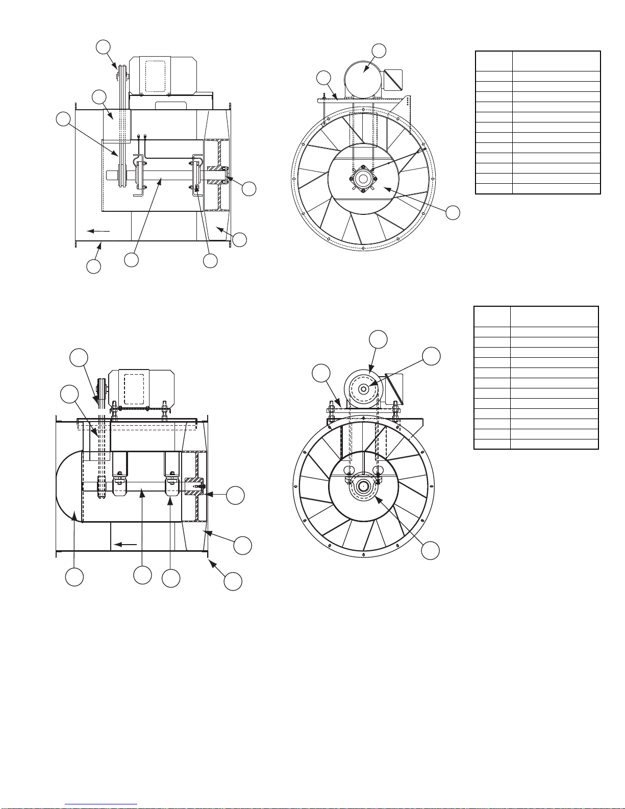
Lubrication - Fan Bearings
Vane Axial bearings are lubricated through a grease fit-
ting on the exterior of the fan housing and should be
lubricated by the schedule, Lubrication Conditions Chart.
For best results, lubricate the bearing while the fan is in
operation. Pump grease in slowly until a slight bead
forms around the bearing seals. Excessive grease can
burst seals thus reducing bearing life.
Before lubricating, the grease nipple and immediate
vicinity should be thoroughly cleaned without the use of
high pressure equipment. The grease should be supplied
slowly as the bearing rotates until fresh grease slips past
the seal. Excessive pressure should be avoided to pre-
vent seal damage.
Use no more than three injections with a hand-oper-
ated grease gun.
Exceptions to the greasing interval chart:
• Periodic Applications (any break of one week or
more): it is recommended that full lubrication be per-
formed prior to each break in operation.
• Higher Temperature: it is recommended to halve the
intervals for every 30°F increase in operating tempera-
ture above 120°F not to exceed 230°F for standard bear-
ings; High Temperature bearings (optional) can operate
up to 400°F.
• Vertical Shaft: it is recommended that the intervals
should be halved.
Loren Cook Company uses petroleum lubricant in a
lithium base. Other types of grease should not be used
unless the bearings and lines have been flushed clean. If
another type of grease is used, it should be a lithium-
based grease conforming to NLGI grade 2 consistency.
A NLGI grade 2 grease is a light viscosity, low-torque,
rust-inhibiting lubricant that is water resistant. Its temper-
ature range is from -30°F to +200°F and capable of inter-
mittent highs of +250°F. For temperatures above 250°F
Mobiltemp SHC 32 is recommended.
Lubrication - Motor Bearings
Motors are provided with prelubricated bearings. Any
lubrication instructions shown on the motor nameplate
supersede instructions below.
Motor bearings without provisions for relubrication will
operate up to 10 years under normal conditions with no
maintenance. In severe applications, high temperatures
or excessive contaminates, it is advisable to have the main-
tenance department disassemble and lubricate the bear-
ings after 3 years of operation to prevent interruption of
service.
For motors with provisions for relubrication, follow inter-
vals of the table below.
Motors are provided with a polyurea mineral oil NGLI #2
grease. All additions to the motor bearings are to be with a
compatable grease such as Exxon Mobil Polyrex EM and
Chevron SRI.
The above intervals should be reduced to half for vertical
shaft installations.
Motor Services
Should the motor prove defective within a one-year
period, contact your local Loren Cook representative or
your nearest authorized electric motor service representa-
tive.
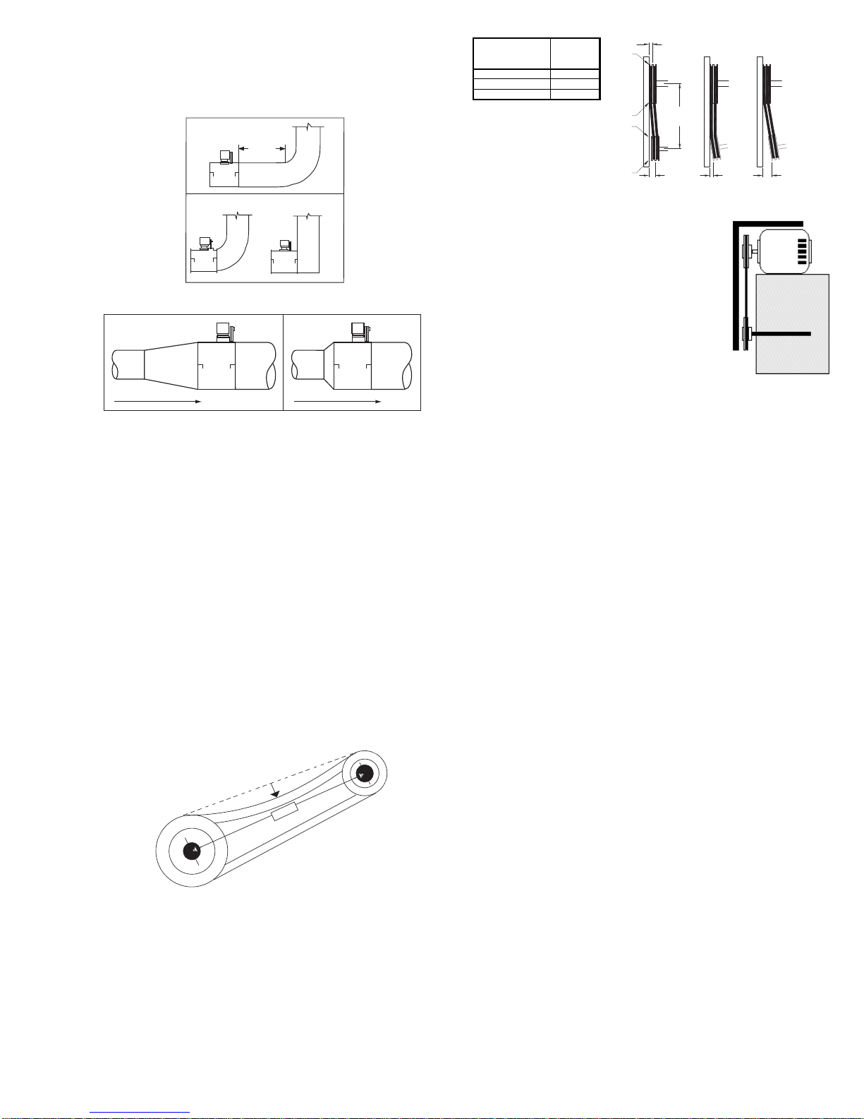
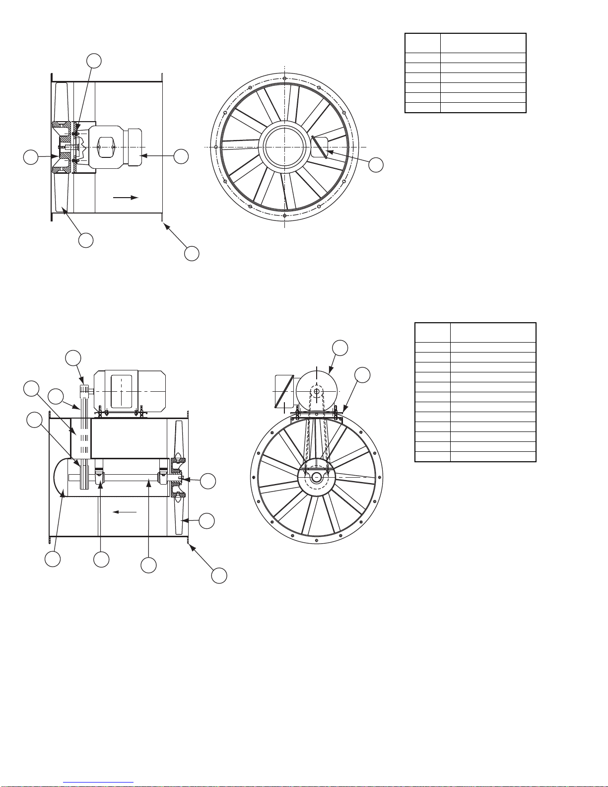
Changing Shaft Speed
All belt driven AF fans with motors up to and including 5
HP are equipped with variable pitch pulleys. To change the
fan speed, perform the following:
a. Loosen setscrew on driver (motor) pulley and remove
key, if equipped.
b. Turn the pulley rim to open or close the groove facing.
If the pulley has multiple grooves, all must be adjusted
to the same width.
c. After adjustment, inspect for proper belt tension.
Speed Reduction
Open the pulley in order that the belt rides deeper in
the groove (smaller pitch diameter).
Speed Increase
Close the pulley in order that the belt rides higher in
the groove (larger pitch diameter). Ensure that the RPM
limits of the fan and the horsepower limits of the motor
are maintained.
The AVAB and VAB have standard fixed pitch
sheaves. To change speeds, consult factory.
Pulley and Belt Replacement
a. Remove pulleys from their respective shafts.
b. Clean the motor and fan shafts.
c. Clean bores of pulleys and coat the bores with heavy
oil.
d. Remove grease, rust, or burrs from the pulleys and
shafts.
e. Remove burrs from shaft by sanding.
f. Place fan pulley on fan shaft and motor pulley on its
shaft. Damage to the pulleys can occur when exces-
sive force is used in placing the pulleys on their
respective shafts.
Relubrication Intervals
Service
Conditions
NEMA Frame Size
Up to and
including 184T 213T-365T 404T and larger
1800RPM
and less Over1800
RPM 1800RPM
and less Over1800
RPM 1800RPM
and less Over 1800
RPM
Standard 3 yrs. 6 months 2 yrs. 6 months 1 yr. 3 months
Severe 1 yr. 3 months 1 yr. 3 months 6 months 1 months
Lubrication Conditions Chart
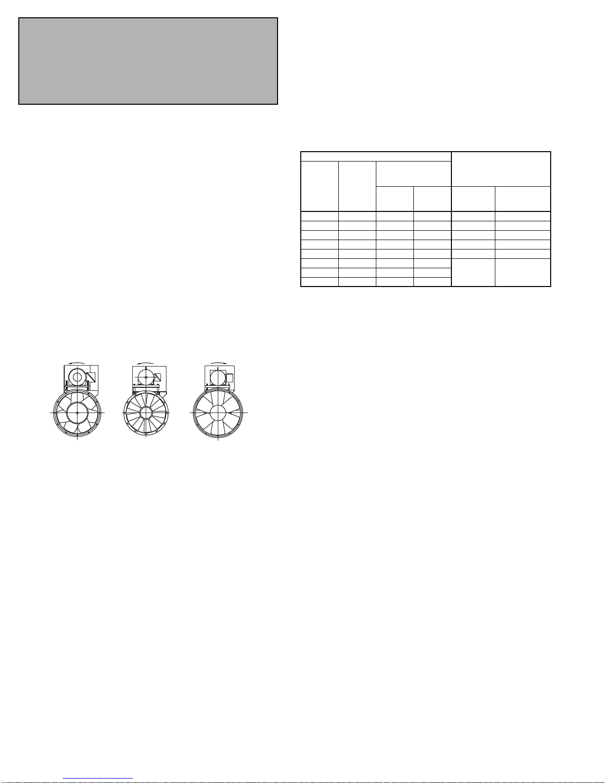
Fan Class Fan Status Fan Operating
Temperature (F) Maximum Interval
(operational hrs)
Inlet Vane
Axial Blowers
Normal Conditions
(Clean, Dry & Smooth)
up to 120 4,500
121 to 160 1,500
161 to 200 700
201 to 400 (*) 200
Extreme Conditions
(Dirty/Wet/Rough)
up to 160 700
161 to 200 400
201 to 400 (*) 200

8
g. Tighten in place.
h. Install belts on pulleys and align as described in the Belt and
Pulley Installation section.
Bearing Replacement
The fan bearings are pillow block ball bearings.
a. Loosen and remove belts by lowering motor mounting plate
with the four adjusting nuts.
b. Remove the bearing cover. Do not remove fan sheave yet.
c. Remove prop by loosening setscrews and retaining bolts and
sliding off shaft.
d. Record the location of the fan sheave from end of shaft, and
remove the sheave.
e. Record the distance from the bearing to the end of the shaft.
f. Loosen setscrews on bearings and remove shaft.
g. Remove bearings and replace with new bearings.
h. Slide shaft through bearings until shaft protrudes the same
amount as original shaft. Tighten setscrews.
i. Replace fan sheave in original location.
j. Replace prop but do not tighten yet.
k. Slide prop on shaft and center prop.
l. Replace and tighten belts.
m. Test run the fan.
n. Re-tighten setscrews on bearings, sheave, and prop. Recheck
belt tension and adjust as needed.
o. Replace bearing cover.
Prop Adjustment
The AVA prop pitch is adjustable. Consult factory for procedure.
6
5
4
3
21
Airflow
VAD Parts List
Item
No. Description
1 Drum Weldment
2 Propeller Fixed Pitch
3 Prop Bushing
4 Motor
5 Wiring Box
6 Motor Mounting Bolts

9
VAB Parts List
123
4
5
10
6
12
7
9
8
Airflow
Item
No. Description
1 Drum Weldment
2 Shaft
3 Bearing (2)
4Prop
5 Prop Bushing
6 Belt Tunnel
7 Motor Plate
8 Inner Drum Nose
9Motor
10 Drive Sheave
11 Driven Sheave
12 Belt
VAHB Parts List
10
9
8
7
6
5
4
3
12
1
2
11
Airflow
Item
No. Description
1 Drum Weldment
2 Shaft
3 Bearing (2)
4Prop
5 Prop Bushing
6 Belt Tunnel
7 Motor Plate
8 Inner Drum Nose
9 Motor
10 Drive Sheave
11 Driven Sheave
12 Belt

10
AVAB Parts List
Airflow
21
3
4
5
6
7
8
9
10
11
12
Item
No. Description
1 Drum Weldment
2Shaft
3 Bearing
4Prop
5 Prop Bushing
6 Motor Plate
7 Inner Drum Nose
8 Motor
9 Drive Sheave
10 Driven Sheave
11 Belt
12 Belt Tunnel (2)
AVAD Parts List Item
No. Description
1 Drum Weldment
2Prop
3 Prop Bushing
4 Motor
5WiringBox
6 Motor Mounting Bolts
1
2
6
4
35
Airflow

11
AFD-C Parts List
Airflow
4
5
3
21
Item
No. Description
1 Drum Weldment
2 Propeller
3 Prop Bushing
4 Motor
5 Motor Mounting Bolts
AFBV Parts List
Airflow
1
4
2
8
7
9
3
6
5
10
11
12
Item
No. Description
1 Drum Weldment
2 Shaft
3Bearing
4 Motor Plate
5
Prop
C-Cast Bushing
H-High Temperature
Construction
S-Stainless Steel
Construction
6PropBushing
7 Bearing Cover
8 Motor
9 Drive Sheave
10 Driven Sheave
11 Belt
12 Vane Section
AFB Parts List
Airflow
1
4
2
8
7
9
3
6
5
10
11
Item
No. Description
1 Drum Weldment
2 Shaft
3 Bearing
4 Motor Plate
5
Prop
C-Cast Bushing
H-High Temperature
Construction
S-Stainless Steel
Construction
6 Prop Bushing
7 Bearing Cover
8 Motor
9 Drive Sheave
10 Driven Sheave
11 Belt

12
Corporate Offices: 2015 E. Dale Street Springfield, MO 65803 417.869.6474
lorencook.com VA/AVA/AF IOM - AUG 2009
Limited Warranty
Loren Cook Company warrants that your Loren Cook fan was manufactured free of defects in materials and workmanship, to the extent stated herein. For a period of one (1)
year after date of shipment, we will replace any parts found to be defective without charge, except for shipping costs which will be paid by you. This warranty is granted only to
the original purchaser placing the fan in service. This warranty is void if the fan or any part thereof has been altered or modified from its original design or has been abused, mis-
used, damaged or is in worn condition or if the fan has been used other than for the uses described in the company manual. This warranty does not cover defects resulting from
normal wear and tear. To make a warranty claim, notify Loren Cook Company, General Offices, 2015 East Dale Street, Springfield, Missouri 65803-4637, explaining in writing,
in detail, your complaint and referring to the specific model and serial numbers of your fan. Upon receipt by Loren Cook Company of your written complaint, you will be notified,
within thirty (30) days of our receipt of your complaint, in writing, as to the manner in which your claim will be handled. If you are entitled to warranty relief, a warranty adjustment
will be completed within sixty (60) business days of the receipt of your written complaint by Loren Cook Company. This warranty gives only the original purchaser placing the
fan in service specifically the right. You may have other legal rights which vary from state to state.
Troubleshooting
Problem and Potential Cause
Low Capacity or Pressure
•Incorrect direction of rotation. Make sure the fan rotates in same direction as the arrows on the motor or belt drive assembly.
•Poor fan inlet conditions. There should be a straight clear duct at the inlet.
•Improper prop alignment.
Excessive Vibration and Noise
•Damaged or unbalanced wheel.
•Belts too loose; worn or oily belts.
•Speed too high.
•Incorrect direction of rotation. Make sure the fan rotates in same direction as the arrows on the motor or belt drive assembly.
•Bearings need lubrication or replacement.
•Fan surge.
Overheated Motor
•Motor improperly wired.
•Incorrect direction of rotation. Make sure the fan rotates in same direction as the arrows on the motor or belt drive assembly.
•Cooling air diverted or blocked.
•Improper prop clearance.
•Incorrect fan RPMs.
•Incorrect voltage.
Overheated Bearings
•Improper bearing lubrication
•Excessive belt tension.
Airflow
4
5
3
21
6
AFDV-C Parts List Item
No. Description
1 Drum Weldment
2 Propeller
3 Prop Bushing
4 Motor
5 Motor Mounting Bolts
6 Vane Section
This manual suits for next models
2
Table of contents
Popular Blower manuals by other brands

Tanaka
Tanaka TRB 24EAP Safety instructions and instruction manual

Wolf Garten
Wolf Garten LBB 36 operating instructions

Poulan Pro
Poulan Pro BVM200VS instruction manual

Stark
Stark 1200CFM Owner's manual and safety instructions

Hitachi
Hitachi RB 36DA Handling instructions

Billy Goat
Billy Goat QUIET BLOW QB1100HPN parts list