1/12 Page 3
Copyright © 2008 Lortone, Inc
LORTONE, inc • 12130 Cyrus Way, Mukilteo, WA 98275 U.S.A
Phone: 425-493-1600 • www.lortone.com
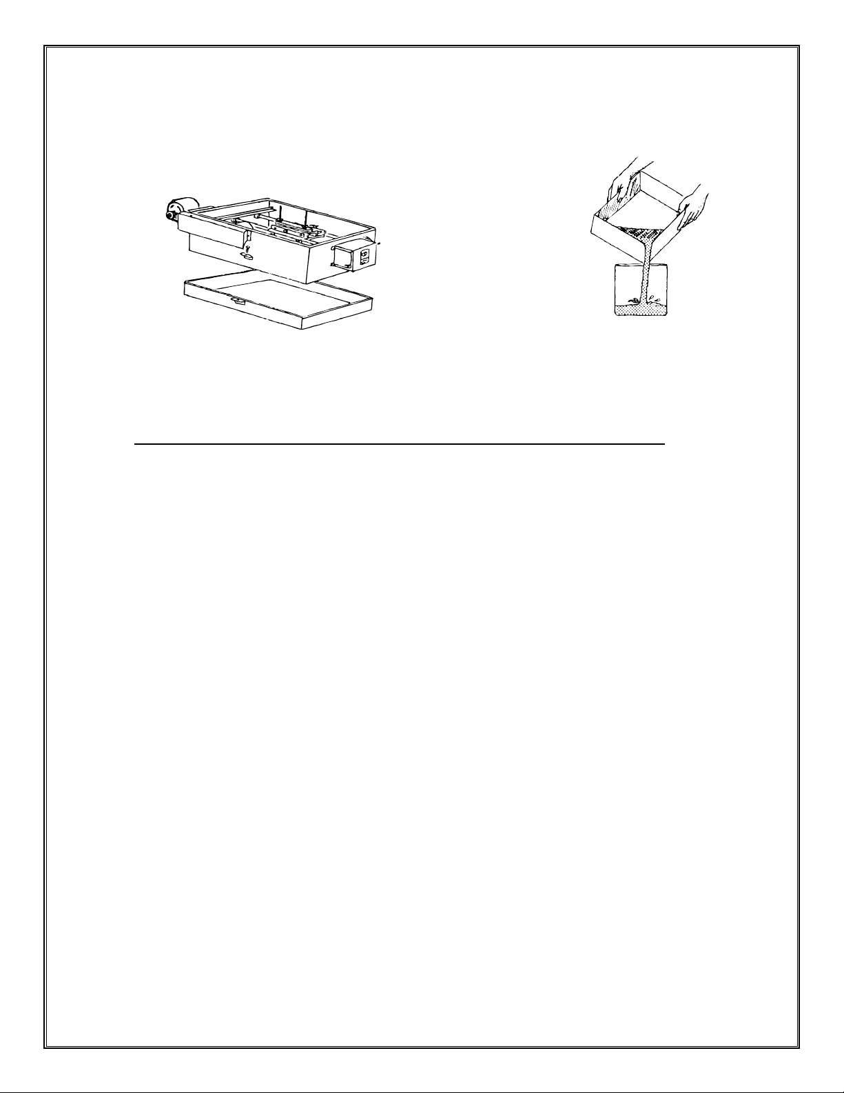
COOLANT
We recommend LORTONE Cutting Oil #086-010 for optimal results.
Use a neutral petroleum base oil with a high ash point and no additives.
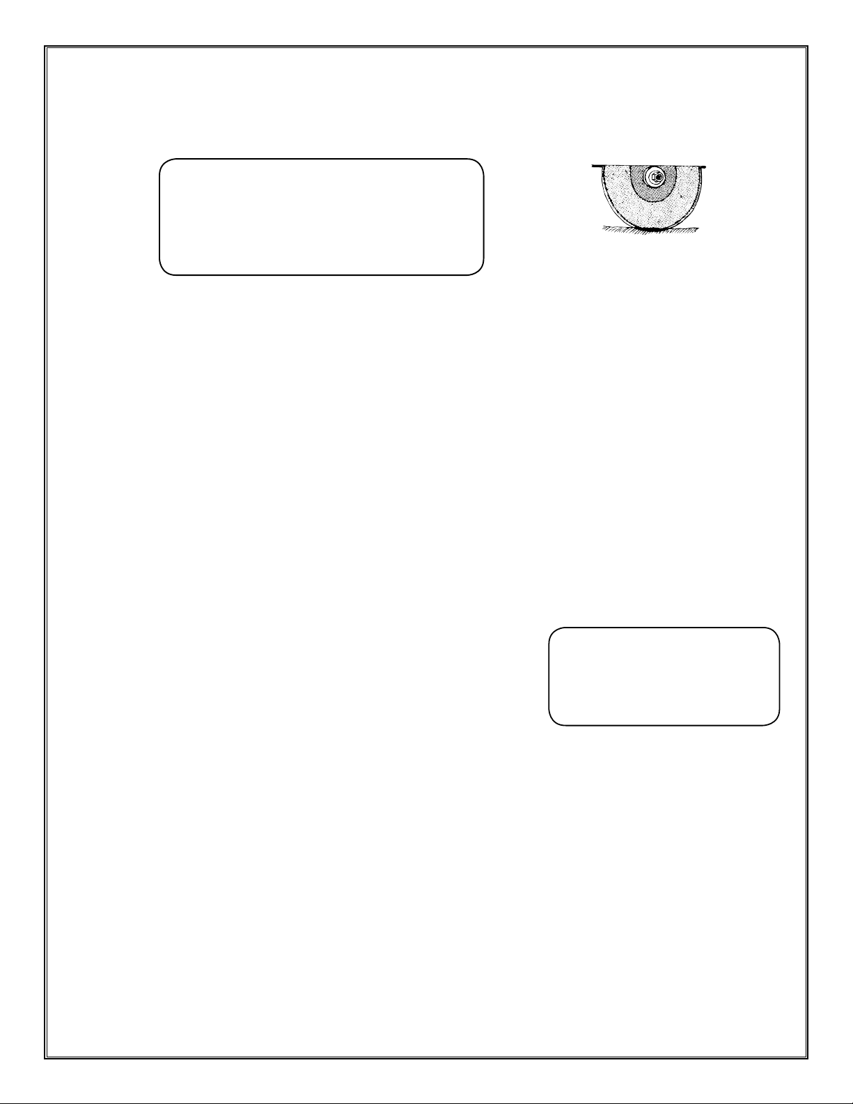
Add approximately 2 gallons of coolant until the bottom 1/4”-1/2” of the blade is covered.
BLADE CARE & DRESSING
Clamp a Blade Dressing Stick in the vise. With the hood closed and the saw running, lightly pull the blade
sharpener handle forward. Repeat as needed.
Dress the blade frequently. Dull or glazed blades will quickly dish or warp.
Note: Dished or warped blades are not covered under warranty.
YOU MUST DRESS THE BLADE PRIOR TO INITIAL USE.
This removes the protective paint from the cutting edge of the blade.
OPERATION
Make sure all Switches on Control Box are in the “OFF” position (toward saw) before opening the hood.
Clamp material securely in vise. Check for looseness of material and re-tighten if necessary.
Adjust cross feed and hand tighten the carriage lock screw #488-056. See Fig A.
Check to be sure that material will clear the arbor shaft cover and the blade anges.
To release carriage, pull half nut lever toward control box. Slide the carriage to desired position and release
the half nut lever. Make sure the lever is fully engaged.
Adjust shutoff chain #447-001 for desired length of cut.
To Start Saw:
Note: The “Power” switch operates the motor and supplies power
to the “Feed” switch. The “Feed” switch operates the feed motor only
and will not work with the “Power” switch in the off position.
Close hood and make sure both switches are in the “OFF” position.
Turn the “Power” switch to “ON” position to start blade rotation.
To start power feed, turn “Feed” switch to “ON” position.
While Cutting: IMPORTANT- DO NOT LEAVE SAW UNATTENDED
Listen for changes in operating noise. Sudden changes can indicate damaged material or blade.
Over-heating of the main motor can result in tripping of the safety overload protector.
Note: Tripping the safety overload protector does not shut off the power feed. To prevent blade & saw
damage, IMMEDIATELY turn off both the “Power” & “Feed” switches. Inspect the machine and blade for
damage and correct any problems before continuing. When cool, press the red reset button on the drive
motor to reset the protector.
At End of Cut:
Push both switches toward saw to “OFF” position before opening the hood.
Remove the cut slab. Inspect the remaining material to make sure it is secure in the vise.
Loosen carriage lock screw and advance the carriage by turning the cross-feed wheel.
Each turn advances the cross-feed carriage approximately 1/16 inch (.062).
Coolant 1/4”-1/2” on Blade
CAUTION
DO NOT run saw without proper coolant.
DO NOT use Kerosene or other ammable solvents.
DO Not use water or water soluble oils.
Failure to follow these instructions can result in
damage to machine or serious injury to operator.
Use of these coolants will void the warranty.
•
•
•
•
•
•
•
•
•
•
•
•
•
•
•
•
•
•
CAUTION
Do not operate saw with Hood open.
Turn off both switches and unplug
saw prior to opening hood.
Failure to follow these instructions
can result in serious injury.