Louet Magic Dobby User manual


1
Installing the electronic interface
If the interface is a replacement for
a mechanical dobby system on
your Magic Dobby, you have to
disassemble this system first by
removing the chain guide and the
bar selector.
Parts included with the interface:
•1 power cable
•1 USB cable
•1 USB stick with drivers
•1 adjustable block for activating
the sensors
•2 screw knobs for securing the
interface
Assembling the adjustable block
1.
2.
3.
1. Disassemble the adjustable
block.
2. Place the part with the bolts
(backside) on the backside of
the knife, with the bolts sticking
out to the right side of the loom
(where the interface will be
placed).
3. Mount the part with the switch
block on the backplate and
secure it with the plastic nuts.
Tighten the nuts so that the
distance between the metal
strips remain the same.
The adjustable block needs to be placed close to the cord going down, and
the switch block should be just under the middle of the knife. After placing
the interface on the loom the exact position will be checked.

2
Place the interface over the
threaded ends.
After checking the position of the
interface it will be secured in place
with the screw knobs.
There are two sensors on the
interface (up and down).
The adjustable block should be
aligned with these sensors.
Checking placement of the switch block
The height of the switch block relative to the sensors determines when the
solenoids are activated and deactivated.
The solenoids need to be activated when the knife is almost in the bottom
position; the switch block should activate the bottom sensor then. The
solenoids need to be deactivated when the knife is moving up; the switch
block should activate the upper sensor then.
When the knife goes down the bottom sensor should be activated after all
dobby bar hooks of the cycle have returned to their resting position.
If the bottom sensor is activated too soon the adjustable block needs to be
placed a bit higher on the knife.
Before the knife reaches its bottom position, the bottom sensor needs to be
activated again, so there is space for the dobby bar hooks to be pushed
forward. If the bottom sensor is not activated or activated too late, the
adjustable block needs to be placed a bit lower on the knife.

3
Checking the position of interface
Third party software
Since the introduction of our first electronic dobby loom, we have worked
with several weaving software companies. By now, these are the companies
that developed drivers for our interfaces: Fiberworks PCW, PixieLoom,
Proweave, Weave it, Weavemaker, WeavePoint and Winweef.
Correct position interface:
Interface placed too far from knife:
The interface needs to be close
enough to the knife, so activated
solenoids will push the hooks of the
dobby bars over the knife.
Therefore the activated solenoids
should be appr. 1 mm from the
knife. Move the interface box back
or forth to accomplish this.
Secure the interface by screwing
the screw knobs on the threaded
ends.
Adjust the distance between the
switch block and sensors if needed:
this should be appr. 1 mm.
This can be adjusted by turning the
switch block in or out.

4
Computer installation
The computer requirements for the interface and most weaving software are
very modest, so both new and older computers can be used. The Louët
interface works with various operating systems.
Below the installation for the supported operating systems is described. In
case your computer doesn’t have an internet connection or it can’t find the
appropriate drivers, we have included an USB stick with these drivers. These
drivers can also be downloaded at our website: www.louet.nl.
Windows 8
Installing the driver(s)
Hook up the power cord and USB cord and turn on the power switch.
Windows will search for the driver automatically. Unfortunately Windows will
not find these automatically.
To install the drivers manually, using the supplied usb stick, follow the next
steps:
•click “Start”
•click on the down arrow - “All programs”
•go to “System” and click “Control panel”
•go to “Hardware and sound” and click “Device manager”
•in the list with “Unknown device” there is an exclamation mark at “Weave
ctr”, right-click “Weave ctr”
•click “Update driver software”
•click the last option “Browse my computer for driver software” and go to
the usb stick
•click “Next” and the driver will be installed
When this driver is installed you will see a new unknown device at “Device
manager” “USB Serial Port”. Follow the steps above again to install the
second driver. The interface is ready for use.
Com-port
The weaving software that are currently on the market use a simulated com-
port to communicate with the interface. In “Device manager” of your
computer you can check on which com-port the interface is installed, so you
can set this number in your weaving software.
•click “Start”
•click on the down arrow - “All programs”
•go to “System” and click “Control panel”
•go to “Hardware and sound” and click “Device manager”

5
•doubleclick “Ports (Com & LPT)”
•behind the name “USB Serial Port” the number of the com-port reserved
for the interface is listed
Changing the com-port
If the com-port number reserved for the interface is too high for the weaving
software, it can be changed in the following way:
•doubleclick “USB Serial Port”
•click the tab “Port settings”
•click “Advanced”
•select a com-port that will work with your weaving software and click OK
Windows 10
With Windows 10 usually the installation happens automatically. Problems
with the installation and functioning of the interface can occur, because of a
combination of software, hardware and settings of Windows 10.
OS X
Installation with OS X is usually plug and play. If the drivers aren’t installed
automatically, go to settings and install the Louët drivers manually.
Operating the loom and interface
First turn on your computer. With the power cord and serial/USB cord
hooked up, turn on the power switch of the interface. All the solenoids will be
temporarily activate and immediately de-activate. You will also notice that
the cooling fan runs, and the green light on the control panel turns on.
Start the weaving program on the computer and select a pattern. Now
activate the weaving process on the software. A signal will go from the
computer to the interface, activating the selected solenoids. Push down the
handle and/or the treadle to raise the selected harnesses. You will notice
that after you have started the upward motion of the shafts, at a certain point
the solenoids will be de-activated. This means that the interface is ready for
the next pick. When the treadle is returned to the rest position, a new pick
will be activated by the sensors.
Please note
There is an automatic time-out function build-into the interface. This limits
how long the solenoids will be activated. If this happens to you, just activate
the treadle and/or handle. This will “wake-up” the interface again, and you
can continue to weave.

6
Electronic interface trouble shooting
The interface does not react to a command of the computer
Possible solutions:
•Time-out
There is an automatic time-out function build-into the interface. This limits
how long the solenoids can be activated. If this time-out occurs, just
activate the interface again in your weaving software.
•Determine if you have power.
Turn the power off and on. The green light should come on, indicating
there is power on the interface. Also the solenoids should temporarily
activate and immediately de-activate, and the fan will start running.
If this does not happen, turn off the power. Remove the fuse holder from
the power entry module, and replace the fuses. You need a small
screwdriver to do this. See the installation instructions. Be sure that you
replace the fuse holder in the right direction, showing the appropriate
voltage after closing the window. Repeat the process to confirm you have
power on the interface.
•Run the self-test
Pressing the small red button engages the selftest. When the first
solenoid activates, you can let go off the button. The interface will cycle
through all 24 solenoids, and then it will repeat. You will observe that
there is a time lag before the repeat begins. This is because the interface
has a circuit board for 32 shafts and is cycling through all of them. This
test shows the circuit board is working properly.
You can stop the self-test by pressing it again.
•Determine whether the interface communicates with the computer.
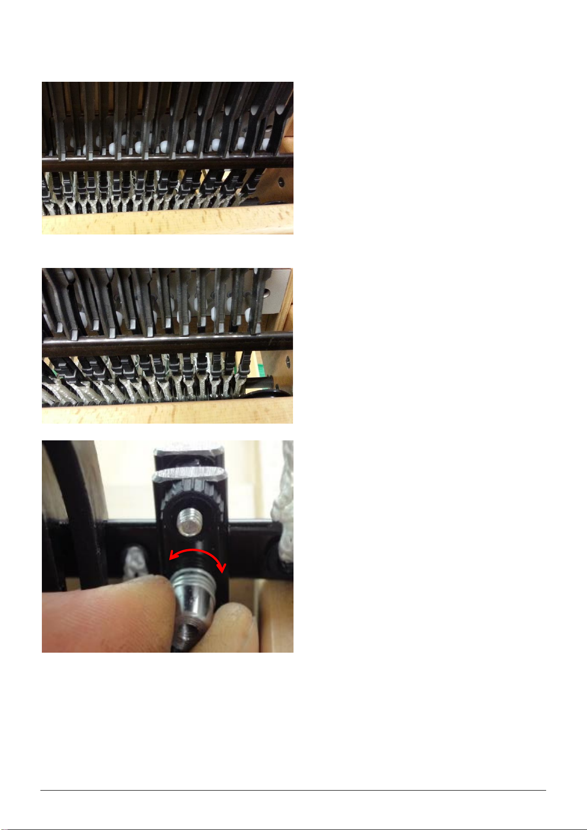
With the interface taken off of the loom, remove the adjustable part from
the lifting bar. Switch on the interface, select a pattern in the weaving
software and tell the software to “WEAVE”. Activate the interface by
manipulating the adjustable part along the sensors. Start at the bottom
and move the adjustable part upward. Reaching the bottom sensor the
first “pick” should activate. Slide the adjustable part up to the upward
sensor and all solenoids will de-activate. Slide the adjustable part back
down to the bottom sensor, where the next pick will activate. This mimics
the action of the loom. The bottom sensor selects the next pick. The top
sensor de-activates the solenoids.
If the solenoids activate according to the signals of the computer, while
manipulating the sensor, the problem is the location of the adjustable part
on the loom.
Solution: You need to re-adjust the location of the adjustable part a bit on
the lifting bar and you can adjust the position of the lifting bar (see
adjusting the lifting bar in the loom instructions).

7
If the solenoids do not activate, there is no communication between the
computer and the interface. Check that the serial/USB cable is connected
properly. Try another serial/USB cable to verify the cable is not faulty.
Warrantee and contact
Louët has a standard warrantee of 2 years for the electronic interface. If you
still have a problem after reading this section, please contact your dealer or
us directly.
Louët BV
Kwinkweerd 139
7241 CW Lochem
The Netherlands

8
Montage elektronische interface
Als de interface een vervanging is
voor de mechanische dobby, moet
deze eerst verwijderd worden.
Meegeleverde onderdelen:
•1 aansluitkabel voor elektriciteit
•1 usb-kabel
•1 usb-stick met drivers
•1 stelblokje t.b.v. activeren
sensors
•2 schroefknoppen t.b.v.
bevestiging interface
Montage stelblokje
1.
2.
3.
1. Demonteer het stelblokje.
2. Plaats het deel met de
uitstekende boutjes (achterplaat)
aan de achterzijde van het mes,
zodat ze naar de rechterzijde
van het getouw wijzen.
3. Plaats het deel met de
schakelbus op de achterplaat en
schroef deze vast met de
moertjes. Moertjes zo vast-
draaien zodat de klemplaatjes
parallel blijven t.o.v. elkaar.
Het stelblokje moet zo dicht mogelijk bij het koord dat naar beneden gaat
worden geplaatst en de schakelbus zal iets onder het midden van het mes
moeten liggen. Na het plaatsen van de interface zal de positie gecontroleerd
worden.

9
Plaats de interface op het getouw,
zodat de draadeinden op het
getouw door de gaten van de
interface steken.
De interface zal na controle van de
positie met de schroefknoppen
worden vastgezet.
Op de interface zitten twee
sensoren (onder en boven).
Het stelblokje op het mes moet
uitgelijnd zijn met de sensoren.
Controle positie schakelbus
De hoogte van de schakelbus ten opzichte van de sensoren bepaald het
moment van activeren en deactiveren van de solenoïden.
De solenoïden moeten worden geactiveerd als het mes bijna in de onderste
positie is, doordat de schakelbus de onderste sensor activeert. De
solenoïden moeten worden gedeactiveerd als het mes naar boven wordt
verplaatst, doordat de schakelbus de bovenste sensor activeert.
Bij het naar beneden gaan van het mes mag de onderste sensor pas worden
geactiveerd als alle dobbyhaken van de cyclus weer terug in de rustpositie
zijn. Gebeurt dit wel dan moet het stelblokje met de schakelbus naar boven
worden gezet.
Voordat het mes in de onderstelstand is, moet de onderste sensor weer
geactiveerd zijn, zodat er ruimte is voor de dobbyhaken om naar voren te
worden geduwd. Als de sensor niet of te laat wordt geactiveerd moet het
stelblokje met de schakelbus naar onderen worden gezet.

10
Software van derden
Al sinds de introductie van onze eerste elektronische dobby getouw werken
we samen met diverse software bedrijven. Op dit moment hebben de
volgende bedrijven software ontwikkeld die geschikt zijn voor onze
interfaces: Fiberworks PCW, PixieLoom, Proweave, Weave it, Weavemaker,
WeavePoint en Winweef.
Correcte positie interface:
Interface te ver van het mes:
Controle positie interface
De interface moet zo dicht tegen
het getouw aanzitten, dat
geactiveerde solenoïden (met witte
dopjes) de haken helemaal over
het mes heen duwen.
Dit kun je bereiken door de
interface zo te plaatsen dat de
afstand tussen de geactiveerde
solenoïden en het mes ongeveer 1
mm is.
Zet de interface kast vast met de
schroefknoppen als deze in de
juiste positie is afgesteld.
Pas de afstand tussen de
schakelbus en de sensoren indien
nodig aan: deze moet ongeveer 1
mm zijn.
Deze afstand kun je aanpassen
door de schakelbus in- of uit te
draaien.

11
Installatie computer
Voor het aansturen van de interface en de meeste weefprogramma's worden
geen hoge eisen gesteld aan je computer. Zowel oude als nieuwe
computers kunnen gebruikt worden. De Louët interface werkt op diverse
besturingssystemen.
Hieronder is de installatie per besturingssysteem beschreven. Mocht het zo
zijn dat je geen internetverbinding heeft of het besturingssysteem de driver
niet kan vinden, is er een usb-stick met de juiste drivers meegeleverd. Deze
drivers kun je ook downloaden op www.louet.nl.
Windows 8
Installeren drivers
Sluit de stroomkabel van de interface aan en koppel de interface met de
usb-kabel aan de computer. Als je de interface aanzet gaat Windows nu zelf
de driver zoeken, maar zal deze niet automatisch vinden.
Om de drivers, welke op de meegeleverde usb-stick staan, handmatig te
installeren doe je het volgende:
•klik 1x op “Start”
•klik 1x op de pijl naar beneden - “Alle programma’s”
•ga naar “Systeem”en klik 1x op “Configuratiescherm”
•ga naar “Hardware en geluiden”en klik op “Apparaatbeheer”
•in de lijst staat bij “Onbekend apparaat” een uitroepteken bij “Weave ctr”,
klik 1x met de rechtermuisknop op “Weave ctr”
•klik 1x op “Stuurprogramma bijwerken”
•klik 1x op de onderste optie “Op mijn computer naar stuurprogramma’s
zoeken” en geef de locatie op van de usb-stick
•klik op “Volgende” en de driver zal geïnstalleerd worden
Als deze driver is geïnstalleerd zie je in “Apparaatbeheer”een nieuw
onbekend apparaat bij “USB Serial Port”. Volg nu dezelfde stappen als
hierboven om de tweede driver te installeren. De interface is daarna klaar
voor gebruik.
Com-poort
De weefsoftware programma’s die momenteel op de markt zijn maken
gebruik van een gesimuleerde com-poort voor de communicatie met de
interface. In het “Apparaatbeheer”van de computer is te zien op welke com-
poort de interface is geïnstalleerd, zodat deze in de weefsoftware kan
worden ingesteld.
•klik 1x op “Start”

12
•klik 1x op de pijl naar beneden - “Alle programma’s”
•ga naar “Systeem”en klik 1x op “Configuratiescherm”
•ga naar “Hardware en geluiden”en klik op “Apparaatbeheer”
•klik 2x op “Poorten (Com & LPT)”
•achter de naam “USB Serial Port” staat het nummer van de com-poort die
momenteel voor de interface is gereserveerd
Aanpassen com-poort
Is er een hoger com-poort nummer gereserveerd dan de weefsoftware kan
gebruiken, kan het com-poort nummer als volgt gewijzigd worden:
•klik 2x op “USB Serial Port”
•klik 1x op het tabblad “Poort instellingen”
•klik 1x op “Geavanceerd”
•selecteer een com-poort die de weefsoftware wel herkend en klik op OK
Windows 10
Bij Windows 10 zal de interface in de meeste gevallen automatisch worden
geïnstalleerd.
OS X
Installatie onder OS X is in de meeste gevallen plug en play. Mocht dit niet
het geval zijn kun je onder settings de drivers handmatig installeren.
Bediening van het getouw en de interface
Start eerst uw computer op. Als de elektriciteitskabel en seriële of USB kabel
aangesloten kun je de interface aanzetten. Alle solenoïdes zullen even
geactiveerd worden. De ventilator en het groene lampje op het controle
paneel gaan beide aan. Start het weefprogramma op uw computer en
selecteer een patroon. Activeer nu het weefproces binnen het
weefprogramma. Een signaal van de computer naar de interface activeert
een aantal solenoïden die de dobbyhaken over het mes duwen. Waar het
stelblokje op het mes zit, heeft de interface een blokje met een groef waarin
zich twee sensoren bevinden die een schachtcombinatie aan en uit
schakelen als het stelblokje er langs beweegt.
Trek de hendel en/of duw de trapper naar beneden om de geselecteerde
combinatie van schachten omhoog te trekken. Tijdens die beweging,
wanneer alle dobbyhaken door het mes gepakt zijn, schakelt het stelblokje
de solenoids weer uit en is de interface klaar om op commando van de
onderste sensor de volgende combinatie van schachten te selecteren. Dat
commando wordt gegeven als je het vak weer sluit en het mes zich weer in
zijn ruststand bevindt.

13
Wanneer je wacht met openen van het volgende vak zullen de solenoids na
enige tijd automatisch uitgeschakeld worden om te voorkomen dat de
interface te warm wordt. Afhankelijk van je software gebruik je de hendel of
de software om de interface opnieuw te activeren.
Wat er mis kan gaan
De interface reageert niet op een commando van de computer
Mogelijke oplossingen:
•Time-out
Er is een automatische time-out functie in de interface ingebouwd. Deze
zorgt ervoor dat na een bepaalde tijd de solenoïdes uitgeschakeld
worden. Je kunt de interface dan in je weefsoftware opnieuw activeren,
zodat je weer verder kunt.
•Controleer of er stroom is
Zet de stroom uit en aan. Het groene lampje zou aan moeten gaan, wat
aangeeft dat er stroom op de interface staat. Ook horen de solenoïdes
tijdelijk geactiveerd en direct gedeactiveerd te worden en zal de ventilator
aangaan.
•Activeer de zelftest
De zelftest wordt geactiveerd door op de rode knop te drukken. Als de
eerste solenoïde actief wordt kun je de rode knop loslaten. De interface
zal alle solenoïdes één voor één activeren en deactiveren. Hierna zal dit
steeds na een pauze herhaald worden. Deze test laat zien dat de
printplaat goed functioneert. Door nog een keer op de rode knop te
drukken wordt de zelftest gestopt.
•Bepaal of de interface met de computer communiceert
Haal de interface en het stelblokje van het getouw af. Activeer de
interface door het stelblokje langs de sensoren te bewegen. Begin bij de
onderkant van het blokje en beweeg het stelblokje langzaam omhoog. Bij
de onderste sensor gekomen zal er een combinatie van solenoïden
geactiveerd worden. Bij het verder omhoog bewegen van het stelblokje,
zullen de solenoïden uitgeschakeld worden bij het bereiken van de
bovenste sensor. Beweeg het stelblokje terug naar de onderste sensor en
de volgende combinatie van solenoïden zal ingeschakeld worden.
Als op deze wijze de solenoïden geactiveerd kunnen worden, is de
oorzaak van het probleem in de plek waar de stelblokje zich op het mes
bevond.
Oplossing: probeer het stelblokje naar een plek op het mes te
verschuiven, waar het tijdens de op- en neergaande beweging de
sensoren activeert.
Wanneer bij de handmatige beweging van het stelblokje de solenoïden
niet reageren, is er geen communicatie tussen de computer en de

14
interface. Controleer de aansluitingen van de kabel. Probeer een andere
USB of seriële kabel om uit te sluiten dat een breuk in de kabel de
oorzaak is.
Garantie en contact
Louët biedt een volledige garantie van 2 jaar aan voor de elektronische
interface. Als je na het lezen van deze handleiding nog steeds een probleem
hebt kun je contact opnemen met je dealer, of eventueel rechtstreeks met
ons.
Louët BV
Kwinkweerd 139
7241 CW Lochem
Nederland
T: + 31 (0)573-252229
F: + 31 (0)573-253858
Website: www.louet.nl
Table of contents
Languages:
Popular Recording Equipment manuals by other brands

360 Systems
360 Systems Instant Replay DR-554-E owner's manual

Fuji Electric
Fuji Electric OPC-PRT2 instruction manual

Siko
Siko IF09P/1 Translation of the original installation instructions

Roland
Roland RE-150 owner's manual

cymatic audio
cymatic audio LR-16 quick start guide

evertz
evertz PROGUARD quick start guide

XOTIC EFFECTS
XOTIC EFFECTS BRCB-V2 owner's manual

Microchip Technology
Microchip Technology Protouch2 user manual

Yamaha
Yamaha TG300 owner's manual

EarthQuaker Devices
EarthQuaker Devices Afterneath Operation manual

Luminite
Luminite GRAVITON M1 user manual

GÜDE
GÜDE Expert Power Sequencer 8112 Series manual