Louroe AP-2-RM User manual

Model AP-2-RM
2 Zone Rack Mounted Audio Base Station
Dual RCA Cable
AD-1 Power Supply
DESCRIPTION
Models AP-2-RM is a non-alarming audio monitoring base stations mounted in a standard 19” rack for providing 2 audio
zones. The unit has the same amount of audio outputs (RCA) as it does for microphone inputs. Model AP-2-RM will
accommodate two Louroe Microphones and has two line level audio outputs. It contains a built-in speaker for producing
live audio and audio playback from a DVR. In addition, it has a selectable RCA audio output for interfacing with a DVR
with only one audio input, or with a VCR. Zone selection is by pushbutton. Contains a Mute switch that mutes the audio
of the remote microphones from being heard at unit’s speaker. All Louroe microphones are compatible with the AP-2-RM.
AP-2-RM
2 ZONE RACK MOUNTED AUDIO BASE STATION
INSTALLATION AND OPERATING INSTRUCTIONS
6955 VALJEAN AVE, VAN NUYS, CA 91406
PH: (818)994-6498 / FAX: (818)994-6458
®
Page 1 of 8
LOUROE ELECTRONICS 6 9 5 5 VA L J E A N AVENUE, VAN NUYS, CA 91406 TEL (818) 994-6498 FAX 994-6458
(818)
®
AP_2_RM_inst_3/15
AP_2_RM_inst_3/15
Contents Description
AP-2-RM listed 2 Zone Rack Mounted Audio
Base Station.
Used for listening to live audio
from microphone, as well as
audio playback from DVR’s, VCR’s
or other audio devices.
AD-1 listed AC ADAPTER.
Supplies 12 Vdc to APR-1 and
Microphone.
Dual RCA Cable RCA cable for connection to a
DVR/VCR or other Audio devices
that accept line level input
(0dB @ 600W).
U
®
U
®

DESCRIPTION AND FUNCTION OF PARTS
[1] - Play/Mute Switch Used when playing back audio from a recorder or mute the audio
from the microphone. No audio is heard on the Speaker[7] when
this switch is ON.
[2] - Zone Selector Switches Select zone for monitoring. Press switch of desired zone to listen
to live audio. Pressing more than one zone is possible when it is
necessary to monitor more than one zone at a time, but audio
may be difficult to understand if there is audio activity at several
zones. Zone switches light blue when press indicating active
zone.
[3] - Headset Jack Used for private listening. Any stereo headset with 8 to 600W
impedance maybe used. Mutes speaker output when use.
[4] - Power Indicator Lights (green) when power is turned ON.
[5] - Power-Volume Knob Rotating knob clockwise turns ON power to the unit as indicated
by the Power Indicator[4] light. Rotating further clockwise
increases the volume of the monitored audio as heard through
the Monitor Speaker[7].
Fig. 1 Front of AP-2-RM
INSTALLATION AND OPERATING INSTRUCTIONS
Page 2 of 8
LOUROE ELECTRONICS 6 9 5 5 VA L J E A N AVENUE, VAN NUYS, CA 91406 TEL (818) 994-6498 FAX 994-6458
(818)
®
4321
AP_2_RM_inst_3/15
5
7

Fig. 2 Rear view of AP-2
DESCRIPTION AND FUNCTION OF PARTS
[6] - Mic Input 3-Pin Terminal Block Connects to remote Louroe microphones.
[7] - Monitor Speaker Provides live audio through the 3” built-in speaker. Muted when
a headset is connected to Headset Jack[3].
[8] - Audio In Jack (RCA) Receives audio playback from DVR/VCR, etc. and is broadcast
through the built-in speaker. [7].
[9] - Audio Out Jack (RCA) Provides audio to DVR/VCR for recording or to other audio
devices accepting line level input when any of the Zone Selector
Switches[2] are activated or push in. The audio output to this
jack will be the audio selected by the Zone Selector Switches[2].
[10]- Power Jack Accepts 12Vdc from external power supply (included)
[11] - Mic Output Jack Used for connection to a DVR with multiple audio inputs or to a
soundcard module for audio recording. May also be used for
paralleling to a second Louroe audio base station.
INSTALLATION AND OPERATING INSTRUCTIONS
Page 3 of 8
LOUROE ELECTRONICS 6 9 5 5 VA L J E A N AVENUE, VAN NUYS, CA 91406 TEL (818) 994-6498 FAX 994-6458
(818)
®
6
11
89
10
AP_2_RM_inst_3/15

MICROPHONE CONNECTIONS TO AP-2-RM
A 12Vdc power supply is included with the above units. First connect the small end with the 90° plug to the above
units Power Jack[10] and connect large end to a standard 120Vac outlet or power strip.
Maximum distance between AP-2-RM, etc. and Louroe microphones is 1,000 ft. (305m)
CONNECTING AP-2-RM TO A RECORDING DEVICE (DVR, ETC.)
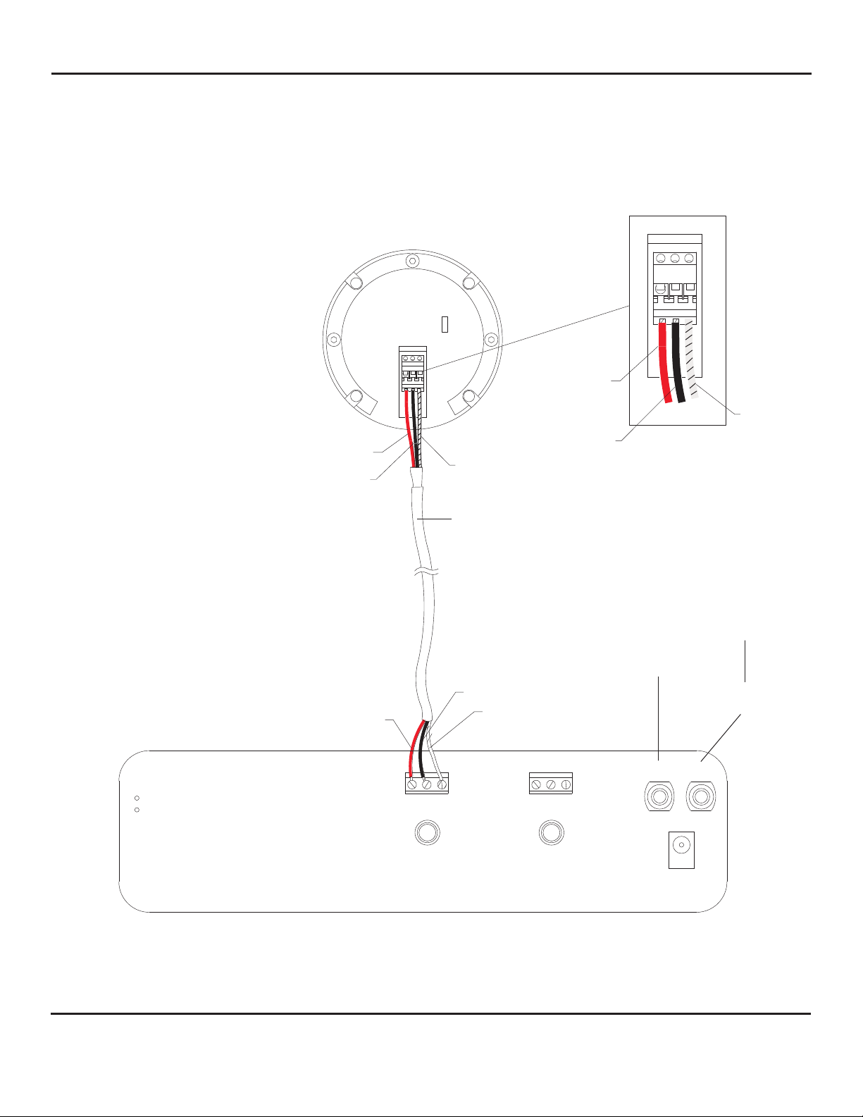
All Louroe Verifact Microphones contain a 3-pin terminal block marked A, B, C. All Louroe base stations contain similar
3-pin terminal blocks marked A, B, C. Refer to interconnection diagram p 5. Using sample cable:
A = 12Vdc Power (red wire)
B = Audio Output (black wire)
C = Common Ground (bare wire)
1) Take one end of recommended cable to first microphone location and connect:
Red wire to terminal A (12Vdc)
Black wire to terminal B (Audio Output)
Bare wire to terminal C (Ground)
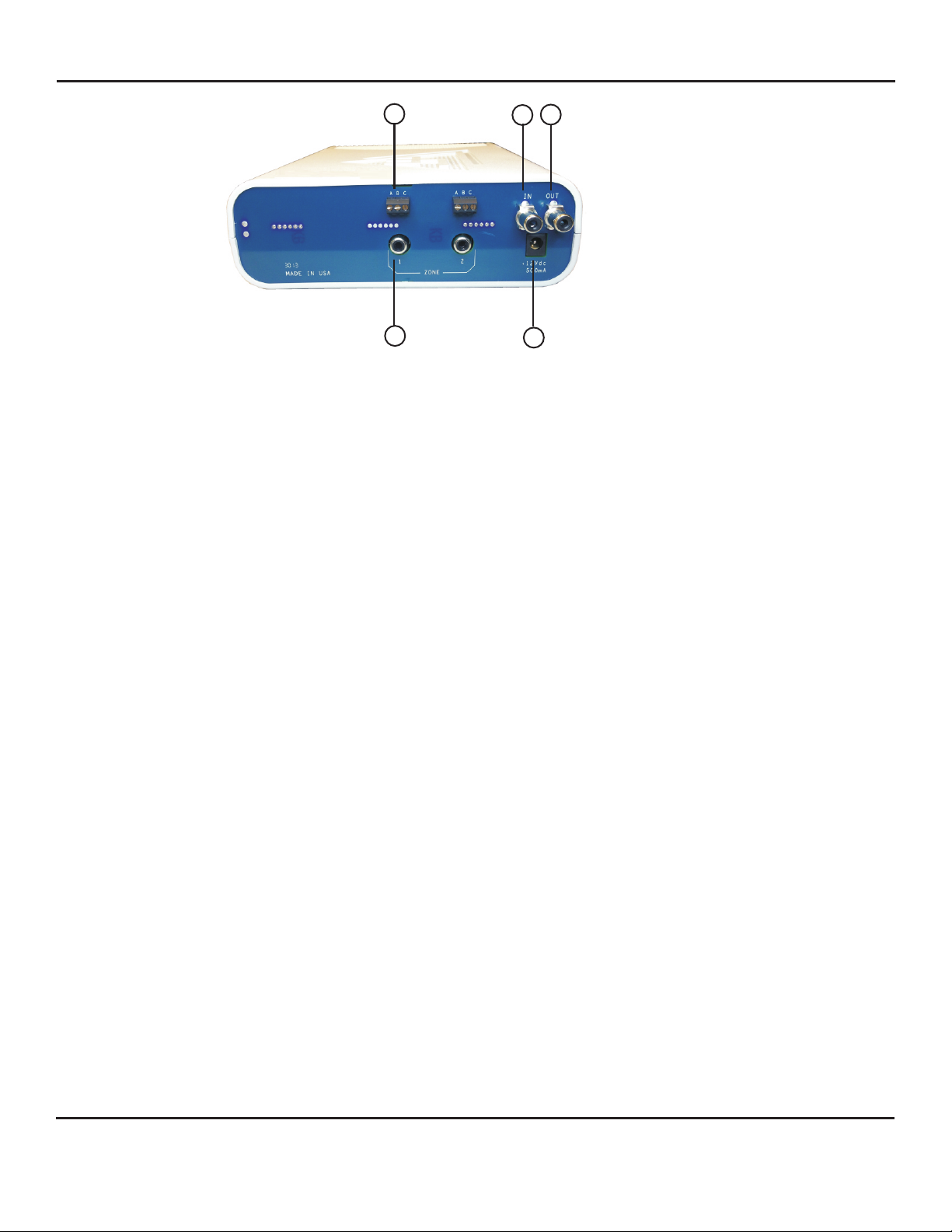
2) Run other end of cable to the AP-2-RM Base Station location and connect to the Mic Input 3-Pin Terminal
Block[6] of the audio zone in which the remote microphone is assigned (example zone 1). Again connect
Red wire to Pin A, Black wire to Pin B and Bare wire to Pin C.
3) Repeat the same procedure for the remaining microphones using the additional terminal blocks marked zone
2, zone 3, etc.
A) If connecting to a DVR with one audio input:
1) Connect an RCA cable to the Audio Out jack [9] of AP-2-RM and connect other end to Audio In (or line
in) of VCR/DVR
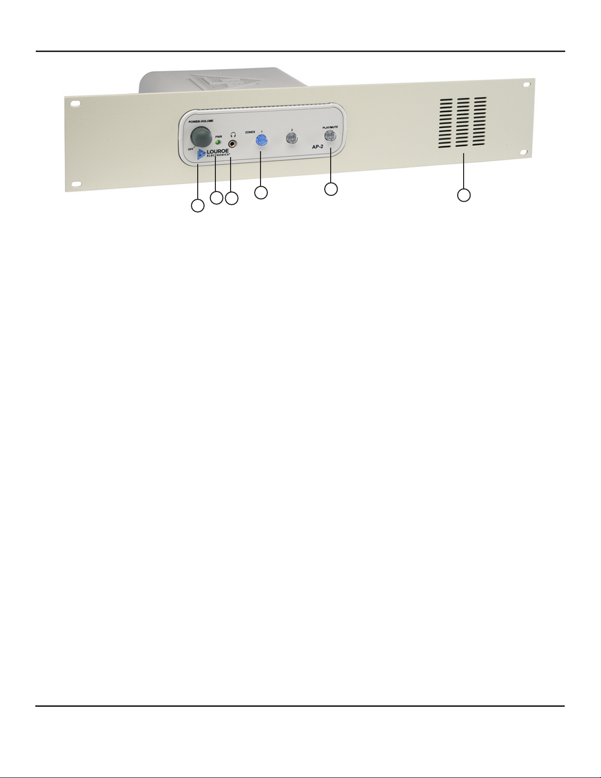
2) To record a particular zone, press the Zone Selector Switch [2] located on front panel of base station
for the audio zone to be recorded
3) For audio playback, connect another RCA cable from Audio Out (or line out) of VCR/DVR to Audio In
[8] of AP-2.
4) Press in the Mute/Playback button[1] of front panel
5) Press the play or playback button on VCR/DVR to start audio playback. Playback will be broadcast
through the base station’s built-in Monitor Speaker[7]. As an alternate, playback may be channeled
through a CCTV monitor with amplifier or through DVR’s speaker system
2) If connecting to a DVR with multiple audio inputs or to a soundcard module:
AP-2-RM has 2 line level RCA Mic Output Jacks [11]
1) Connect RCA cables between the Mic Output Jacks [11] and Audio Inputs of DVR matching zone 1 to
channel 1 of the DVR audio inputs.
2) For audio playback from base station, press in the Play/Mute Switch[1] located on base station’s front
panel. Playback may also be channeled through other audio sources
APPLYING POWER TO THE AP-2-RM
INSTALLATION AND OPERATING INSTRUCTIONS
Page 4 of 8
LOUROE ELECTRONICS 6 9 5 5 VA L J E A N AVENUE, VAN NUYS, CA 91406 TEL (818) 994-6498 FAX 994-6458
(818)
®
®
AP_2_RM_inst_3/15

INSTALLATION AND OPERATING INSTRUCTIONS
INTERCONNECTION DIAGRAM FOR VERIFACT A MICROPHONE
AND AP-2-RM BASE STATION
Page 5 of 8
LOUROE ELECTRONICS 6 9 5 5 VA L J E A N AVENUE, VAN NUYS, CA 91406 TEL (818) 994-6498 FAX 994-6458
(818)
ABCC
B
A
12
IN OUT
N
L
A B C
CBA
Red(A)
Black(B)
Bare(C)
Red(A)
Black(B) Bare(C)
Red(A)
Black(B)
Bare(C)
12Vdc
SELECTABLE
AUDIO OUTPUT
Use if recording device
has only one Audio Input
Use for audio playback
from recording device
WIRING REQUIREMENTS
VERIFACT A MICROPHONE
REAR OF AP-2-RM BASE STATION
2 Cond Shielded Cable
22 Gauge with a 24 Gauge
Drain wire.
®
®
AP_2_RM_inst_3/15

OPERATION AND TEST
After microphones and power supply are connected, proceed as follows:
1) Turn on power to the unit by rotating the Power-Volume Knob[5] clockwise to “ON” position. The green LED
[4] will illuminate, indicating power to the unit. Rotate Power-Volume Knob[5] further clockwise to increase
the volume of monitored audio.
2) Press Zone Selector Switch[2] marked zone 1. Audio from zone 1 should be present at the Monitor
Speaker[7]. The switch blue light should be ON indicating that zone is activated. If there is no audio, remove
wires connected to Mic Input 3-Pin Terminal Block[6] for zone 1 at the rear of the unit. With a DC voltmeter,
check that 12 Vdc is present at terminals “A” and “C”. If voltage is not present, unit has defective power
supply. If voltage is present, check to assure that wires are connected properly to the right terminals.
Otherwise microphone is defective. Call factory for assistance.
3) Repeat step 2 for the remainder of the zones.
4) When a recorder is connected to the unit, press Play/Mute Switch[1]. The Play/Mute Switch[1] will light. The
audio from the remote microphones are muted. Press DVR playback switch to listen to recorded audio on the
unit’s speaker. The Play/Mute Switch[1] must be depressed or in the “OUT” position to hear live audio again
on the Monitor Speaker[7].
INSTALLATION AND OPERATING INSTRUCTIONS
Page 6 of 8
LOUROE ELECTRONICS 6 9 5 5 VA L J E A N AVENUE, VAN NUYS, CA 91406 TEL (818) 994-6498 FAX 994-6458
(818)
®
AP_2_RM_inst_3/15

INSTALLATION AND OPERATING INSTRUCTIONS
Page 7 of 8
LOUROE ELECTRONICS 6 9 5 5 VA L J E A N AVENUE, VAN NUYS, CA 91406 TEL (818) 994-6498 FAX 994-6458
(818)
®
Shipping Weight 4 lbs
SPECIFICATIONS
Monitor power output 1W @ 8
Audio input impedance 10k
Freq. response 100 Hz to 10kHz
Power input 12 Vdc, 500mA
Dimensions 19”L x 3 1/2”W x 8 5/8”D
Headphone impedance
Current Drain
8 to 600
200mA
Weight 2lb 13 oz
Audio output impedance 1K?
AP_2_RM_inst_3/15

MANUFACTURED
IN THE
IMPORTANT NOTICE
When this equipment is used as part of an
audio monitoring system, the law requires
that the public be given notice of AUDIO
MONITORING ON THE PREMISES. A
decal notice is included with each
microphone shipped.
Federal Law References:
Federal Regulations, US Code, Title 18.
Crime and Criminal Procedure, Sec 2510.
Page 8 of 8
LOUROE ELECTRONICS 6 9 5 5 VA L J E A N AVENUE, VAN NUYS, CA 91406 TEL (818) 994-6498 FAX 994-6458
(818)
®
AUDIO
MONITORING
On
These Premises
®
AP_2_RM_inst_3/15
WARRANTY
LOUROE ELECTRONICS warrants that at the time of shipment products manufactured by LOUROE
ELECTRONICS to be free of defects in material and workmanship. Should a defect appear within five years (60
months) from date of shipment, LOUROE ELECTRONICS will, at its sole discretion, repair or replace the defective
equipment. This equipment shall not be accepted for repair or return without prior notification by LOUROE
ELECTRONICS .
This warranty does not extend to any Louroe product that has been subjected to improper or incorrect installation,
misuse, accident, or in violation of installation instructions provided by LOUROE ELECTRONICS.
Returned shipments to LOUROE ELECTRONICS shall be at customer’s expense. LOUROE ELECTRONICS will
return the equipment prepaid via best way
Table of contents
Other Louroe Stereo System manuals