Lovato T FAST-I 20 User manual

Lovato S.p.A.
via Selva, 4/A - 37040 Gazzolo d’Arcole
(VR)
Tel. +39 045 618 2012 Fax +39 045 618
2017
www.lovatospa.com
Illustrazioni e dati presenti si intendono non impegnativi. LOVATO SpA si riserva il diritto di apportare modiche senza obbligo di preavviso.
È vietata la riproduzione parziale o totale di disegni, testi o illustrazioni senza autorizzazione scritta.
Picture and technical data are not binding. LOVATO SpA will reserve the right to bring change without obbligation of notice.
It is forbidden reproduce copy, drawing or texties, partial or total without previous written authorization.
Modulo di produzione ACS
DHW production module
Frischwasserstation
Module de production ECS
Istruzioni per l’installazione, l’uso e la manutenzione
Assembling instructions and maintenance
Montage - und Wartungsanleitung
Instructions relatives à l’installation, l’utilisation et la maintenance
www.lovatospa.com
T_FAST-I 20 / T_FAST-I 35

2204010 - 05.13 2
3-4 Introduzione del modulo
5Indicazioni generali
6-7 Installazione del modulo a muro / puffer
8Connessione idraulica - Applicazioni
9Dimensioni, messa in funzione del modulo - Collegamento kit di ricircolo
10 Lavaggio dello scambiatore
Installazione, uso e manutenzione
Illustrazioni e dati presenti si intendono non impegnativi. LOVATO Spa si riserva il diritto di apportare modiche senza obbligo di preavviso.
È vietata la riproduzione parziale o totale di disegni, testi o illustrazioni senza autorizzazione scritta.
Indice

3
22004010 - 05.13
Dati tecnici
Portata massima mandata primario 1.200 l/h
Portata massima uscita secondario (ACS) 1.800 l/h ∆P 0,5 bar
Temperatura ACS 40÷55 °C
Pressione massima di esercizio 10 bar
Alimentazione elettrica 230 V AC
Portata minima produzione ACS / ON 2,5±0,3 l/m
Portata minima intervento ACS / OFF 2,0±0,3 l/m
Supercie scambio scambiatore maggiorato 0,882 mq
Dimens. cassetta contenimento con coibentazione (BxHxP): 400x600x250 mm
Dimensione attacchi 1” M - ¾” F
1
2
3
4
5
6
7
8
9
10
11
12
Circolatore Wilo YONOS PARA 15/1-6 (alternativa con Wilo RS 15/6-3 KU)
Valvola a sfera DN 20 1”M - ¾" F
Maniglia rossa
Maniglia blu
Maniglia nera con termometro rosso
Valvola di non ritorno
Valvola a tre vie miscelatrice con attuatore termostatico 35 - 65°C
Valvola di sato aria manuale da 3/8"
Scambiatore a piastre inox saldobrasato con isolamento
Flussostato
Rubinetto carico-scarico da ½”
Valvola di sicurezza 10 bar
pos. t (°C)
1 35
2 40
3 45
4 50
5 55
6 60
7 65
FERMO TESTA(Figura E)
REGOLAZIONE DI FABBRICA (Figura D)
(Fig. E) (Fig. D)
Attuatore termostatico: regolazione temperatura uscita sanitario
1. Introduzione del modulo T_FAST-I 20
Componenti principali
12 Kit di ricircolo (fornito separatamente) composto da:
circolatore Lowara/Xylem EB15-1/94 R, valvola di ritegno, valvola di
sicurezza 10 bar, tubazioni e kit accessori.
Accessori di completamento
45
40 50 55 60
5
10
15
20
25
30
Q (l/min)
10÷45 °C
10÷48 °C
10÷50 °C
10÷55 °C
65
(°C)
70
10÷42 °C
Graco produzione ACS
Temperatura prelievo accumulo
Produzione ACS
Codici prodotto
T_FAST I 20 con Wilo YONOS PARA 15/1-6 cod. 49060450
T_FAST I 20 con Wilo RS 15/6-3 KU cod. 49060443
Kit di ricircolo sanitario (fornito separatamente) cod. 49060444
Installazione, uso e manutenzione
ITALIANO
1
2
2
3
4
6
8
10
11
11
4
2
2
5
9
7
12

4
2204010 - 05.13
Dati tecnici
Portata massima mandata primario 1.700 l/h
Portata massima uscita secondario (ACS) 2.000 l/h ∆P 0,5 bar
Temperatura ACS 40÷55 °C
Pressione massima di esercizio 10 bar
Alimentazione elettrica 230 V AC
Portata minima produzione ACS / ON 2,5±0,3 l/m
Portata minima intervento ACS / OFF 2,0±0,3 l/m
Supercie scambio scambiatore maggiorato 1,76 mq
Dimens. cassetta contenimento con coibentazione (BxHxP): 400x600x250 mm
Dimensione attacchi 1” M - ¾” F
1
2
3
4
5
6
7
8
9
10
11
12
Circolatore Wilo YONOS PARA 15/1-6 (alternativa con Wilo RS 15/6-3 KU)
Valvola a sfera DN 20 1”M - ¾" F
Maniglia rossa
Maniglia blu
Maniglia nera con termometro rosso
Valvola di non ritorno
Valvola a tre vie miscelatrice con attuatore termostatico 35 - 65°C
Valvola di sato aria manuale da 3/8"
Scambiatore a piastre inox saldobrasato con isolamento
Flussostato
Rubinetto carico-scarico da ½”
Valvola di sicurezza 10 bar
pos. t (°C)
1 35
2 40
3 45
4 50
5 55
6 60
7 65
FERMO TESTA(Figura E)
REGOLAZIONE DI FABBRICA (Figura D)
(Fig. E) (Fig. D)
Attuatore termostatico: regolazione temperatura uscita sanitario
1. Introduzione del modulo T_FAST-I 35
Componenti principali
12 Kit di ricircolo (fornito separatamente) composto da:
circolatore Lowara/Xylem EB15-1/94 R, valvola di ritegno, valvola di
sicurezza 10 bar, tubazioni e kit accessori.
Accessori di completamento
NB: Il corretto funzionamento del modulo è garantito se la temperatura di mandata del primario supera di almeno 5°C la temperatura di set ACS impostata.
Graco produzione ACS
Temperatura prelievo accumulo
Produzione ACS
Codici prodotto
T_FAST I 35 con Wilo YONOS PARA 15/1-6 cod. 49060468
T_FAST I 35 con Wilo RS 15/6-3 KU cod. 49060465
Kit di ricircolo sanitario (fornito separatamente) cod. 49060444
Installazione, uso e manutenzione
1
2
2
3
4
6
8
10
11
11
4
2
2
5
9
7
12

5
22004010 - 05.13
2. Indicazioni generali per l’utente nale
AVVERTENZE GENERALI
Installazione
Tutte le operazioni devono essere fatte con alimentazione disinserita dalla rete elettrica.
L’installazione deve avvenire in conformità alle leggi ed ai regolamenti di ciascun paese.
La responsabilità del produttore è limitata alla fornitura dell’apparecchio. Il suo impianto va realizzato in modo conforme alla regola dell’arte,
secondo le prescrizioni delle presenti istruzioni e le regole della professione, da personale qualicato, che agisce a norma di imprese adatte
ad assumere l’intera responsabilità dell’insieme dell’impianto.
La LOVATO S.p.A. non è responsabile del prodotto modicato senza autorizzazione e tanto meno per l’uso di ricambi non originali.
Collegamento elettrico
L’impianto e/o la centralina dovranno essere installate e collegate da personale abilitato secondo le norme vigenti.
In presenza di centralina elettronica, collegare il cavo di alimentazione della stessa ad interrutore bipolare completo di fusibili (alimentazione
230Vac 50Hz). E’ indispensabile il corretto collegamento all’impianto di messa a terra.
Avvertenza
Il comando deve essere alimentato in rete con a monte un interrutore generale differenziale di linea come dalle vigenti normative. Il corretto
funzionamento del comando è garantito solamente per l’apposito motore per il quale è stato costruito. L’uso improprio solleva il costruttore
da ogni responsabilità.
Collegamento idraulico
Dopo avere trasportato/maneggiato il KIT provvedere al serraggio di tutte le ghiere di ssaggio delle tubazioni.
Prestare particolare attenzione quando si collega il KIT all’impianto idraulico, evitare di piegare i tubi in rame del KIT. Per contrastare
la forza di serraggio esercitata sul tubo di collegamento dell’impianto idraulico, usare una chiave ssa o altro utensile sul terminale
del KIT da collegare.
Consultare attentamente il presente manuale prima di procedere a qualsiasi intervento sull’apparecchiatura.
Il costruttore, al ne di adeguare l’apparecchiatura al progresso tecnologico ed a speciche esigenze di carattere produttivo o di installazione
e posizionamento, può decidere, senza alcun preavviso, di apportare su di essa modiche. Pertanto, anche se le illustrazioni riportate in
questo manuale differiscono lievemente dall’apparecchiatura in vostro possesso, la sicurezza e le indicazioni sulla stessa sono garantite.
Il presente manuale d’uso è parte integrante del prodotto e va custodito in modo adeguato per mantenerne l’integrità e permetterne la
consultazione durante l’arco di vita dell’apparecchiatura.
E’ buona norma che esso rimanga sempre a corredo dell’apparecchio e venga conservato con cura per ogni ulteriore consultazione, anche
nel caso in cui quest’ultimo dovesse essere venduto o trasferito ad altro proprietario o si dovesse traslocare e lasciare l’apparecchio, in
modo che il nuovo proprietario o l’addetto possa consultarlo.
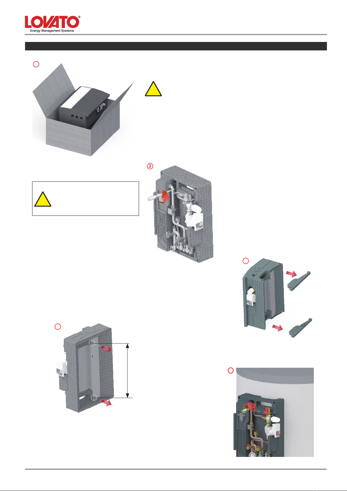
Controlli preliminari
Prima di ogni operazione rimuovere con cura l’imballo e controllare la perfetta integrità dell’apparecchiatura. Nel caso si evidenziassero dei
difetti o dei danni non installare o cercare di riparare l’apparecchiatura ma rivolgersi al rivenditore.
Smaltire le parti di imballaggio in accordo con le leggi e disposizioni vigenti.
Rimane comunque di fondamentale importanza seguire alcuni consigli durante l’uso dell’apparecchio:
• Non toccare parti calde dell’apparecchio quali le tubazioni di ingresso ed uscita dell’acqua. Ogni contatto con esse può provocare
pericolose scottature.
• Non bagnare l’apparecchio con spruzzi d’acqua ed altri liquidi.
• Non appoggiare alcun oggetto sopra l’apparecchio.
• Non esporre l’apparecchio ai vapori provenienti da un piano di cottura.
• Vietare l’uso dell’apparecchio a bambini e a persone inesperte.
• Non toccare l’apparecchio con parti del corpo bagnate o umide e/o piedi nudi.
• Non tirare i li elettrici.
• Indossare guanti di protezione e scarpe antinfortunistiche prima di maneggiare il prodotto
L’installazione, i collegamenti ed il collaudo devono essere afdati a personale qualicato che opera
rispettando le norme vigenti e seguono quanto riportato nel libretto di istruzioni dei termoprodotti.
!
Gentile Cliente,
desideriamo ringraziarLa per aver scelto un prodotto Lovato. Siamo certi che sapremo ricambiare la ducia che ci è stata accordata con un prodotto che è il frutto di un costante
lavoro di ricerca e di una produzione sempre attenta ed orientata alla qualità.
I nostri prodotti inoltre sono costruiti con materiali e componenti di ottima qualità, che ne garantiscono qualità ed afdabilità nel tempo.
Questo libretto contiene, oltre ai dati ed alle caratteristiche dell’apparecchio, una serie di istruzioni che interessano l’installatore, il manutentore e l’utente nale.
Le comunichiamo che l’avviamento dell’apparecchio installato e la convalida della relativa garanzia devono essere richiesti al nostro Centro Assistenza di zona o a tecnici autorizzati.
Per avere il nominativo del Centro Assistenza più vicino o del tecnico autorizzato telefonare al n. 045 6182012.
Per una perfetta messa a punto ed una scrupolosa manutenzione periodica, consigliamo di rivolgersi alla nostra rete di Assistenza Tecnica almeno una volta all’anno: oltre ad offrire
un’indispensabile revisione del modulo termico, essa svolgerà un’azione preventiva tale da evitare inconvenienti o disattivazioni indesiderate.
Nel rinnovarLe il nostro grazie, desideriamo confermarLe la nostra disponibilità per ogni informazione di cui avrà bisogno e per fornirLe tutto il supporto necessario per il buon
funzionamento del prodotto.
LOVATO S.p.A.
ATTENZIONE!
Installazione, uso e manutenzione

6
2204010 - 05.13
3. Installazione del modulo a muro
Installazione, uso e manutenzione
1. Estrarre dall’imballaggio il modulo e rimuovere il coperchio in EPP.
2. Allentare le 2 viti della dima di supporto (g.2) e rimuoverla dalla
parte posteriore del modulo per poi ssarla a parete con n.2 tasselli
da 12 mm (non forniti) come indicato nel rif. 2a
3. Agganciare il modulo alle viti della staffa ssata a muro,
(vedi fori asolati dello schienale), utilizzando le apposite
guide laterali indicate nella g.3a. Successivamente la-
sciar scivolare verso il basso no al completo inseriento
delle viti nele asole. (g.3a).
4. Successivamente avvitare le viti della staffa dalla parte frontale del
modulo, utilizzando gli appositi fori come evidenziato in gura 4.
!
2
IMPORTANTE!
POSIZIONARE LA STAFFA IN
MANIERA CORRETTA
N.B. TASSELLI ESCLUSI DALLA
FORNITURA
3
1
3a
4
2a
!ATTENZIONE!
MANEGGIARE CON CURA!

7
22004010 - 05.13
3. Installazione del modulo su puffer
2. Allentare le 2 viti della dima di supporto (g.2) e rimuoverla
dalla parte posteriore del modulo.
!
ATTENZIONE!
L’INTERASSE DEI FORI VA PREVENTIVA-
MENTE COMUNICATO AL PRODUTTORE DEL
BOILER IN FASE D’ORDINE (SERVIRSI DLLE
DISTANZE NELLA FIGURA 3)
5
3. Estrarre gli inserti in EPP per consentire i collega-
menti idraulici al puffer come indicato in gura.
3
1
1. Estrarre dall’imballaggio il modulo e rimuovere il coperchio in EPP.
!ATTENZIONE!
MANEGGIARE CON CURA!
2
4. Agganciare il modulo al puffer, (vedi fori asolati dello
schienale) e avvitare le viti superiore e inferiore dalla parte
frontale del modulo utilizzando gli appositi fori come evi-
denziato in gura 5.
4
Installazione, uso e manutenzione
465

8
2204010 - 05.13
Per gli impianti di produzione acqua calda sanitaria prevedere un ltro raccogli
impurità per la protezione dell’impianto stesso. Prevedere inoltre una valvola di
ritegno e un vaso di espansione in ingresso AFS come da par. 5
In presenza di acqua con durezza superiore ai 25÷30 °Fr, si prescrive un opportu-
no trattamento in entrata dell’impianto di riscaldamento, al ne di evitare possibili
incrostazioni causate da acque dure o corrosioni prodotte da acque aggressive.
É opportuno ricordare che anche piccole incrostazioni di qualche millimetro di
spessore provocano, a causa della loro bassa conduttività termica, una riduzione
delle prestazioni lato sanitario.
I materiali di costruzione del modulo di produzione acqua calda sanitaria mod.
T_FAST-I 20 e T_FAST-I 35 sono conformi a quanto previsto dal D.M. 174/2004,
regolamentato dalla Direttiva 98/83/CE.
Nonostante la raccorderia sia montata in fabbrica occorre controllare e serrare
ulteriormente tutti i raccordi a vite. Altrettanto è importante fare una prova di tenuta
(prova a pressione) durante la messa in servizio.
Attenzione: il superamento dei valori della tabella di lato potrebbe portare al dan-
neggiamento del modulo T-FAST I e inevitabilmente al decadimento della garanzia.
IMPORTANTE
!
4. Connessione idraulica
Rete AFS
Ritorno primario
Mandata primario
T_FAST-I 20
Uscita ACS
Fonte di calore
Ricircolo
Puffer Puffer
Ricircolo
T_FAST-I 20
Uscita ACS
Rete AFS
Mandata primario
Ritorno primario
Fonte di calore
Esempio di applicazione: installazione a muro Esempio di applicazione: installazione a puffer
Mandata primario
Ritorno primario
Ingresso AFS
Uscita ACS
5. Applicazioni
Installazione, uso e manutenzione
COMPONENTI UNITA’ DI
MISURA
VALORI LIMITE PER SCAMBIATORI
CON SALDATURA IN RAME
PH 7-9 (considerato indice di saturazione)
Indice di Saturazione(delta PH) -0.2<0<+0.2
Durezza Totale °Fr 15-30
Conduttività µS/cm 10...500
Sostanze Filtrabili mg/l <30
Cloro libero mg/l <0.5
Idrogeno Solforato mg/l <0.05
Ammoniaca mg/l <2
Idrogeno Carbonato mg/l <300
Idrogeno Carbonato/Solforato mg/l >1.0
Solfuro mg/l <1
Nitrato mg/l <100
Nitrito mg/l <0.1
Solfato mg/l <100
Manganese mg/l <0.1
Ferro disciolto mg/l <0.2
Anidride Carbonica agressiva libera mg/l <20

9
22004010 - 05.13
6. Dimensioni - Messa in funzione del modulo
1 - Riempire il circuito primario.
2 - Riempire il circuito secondario (sanitario) utilizzando gli appositi rubinetti di
carico/scarico.
3 - Controllare la tenuta idraulica del modulo e satare l’aria presente per un
buon rendimento dell’impianto.
4 - Dare tensione al modulo.
5 - Vericare il corretto funzionamento del circuito.
600
400
7. Collegamento kit di ricircolo - curva circolatore Lowara/Xylem EB15-1/94 R
6565
65
205
65
Installazione, uso e manutenzione
- Intercettare il usso chiudendo le valvola a sfera “ingresso
AFS” rif. 1 e uscita “ACS” rif.2
- Estrarre il tappo 1” F dal modulo T-FAST come indicato
nel rif. 3.
- Inserire il kit di ricircolo (rif.4), avvitando la calotta a tenuta.
- Alimentare la pompa di ricircolo con linea 230V.
- Impostare il valore di temperatura di ritorno ricircolo dal
pannello comandi del circolatore.
PERICOLO!
APPARECCHIO IN TENSIONE
3
1
2
4Valvola di
ritegno
Rubinetto di
intercettazione
F
L
U
S
S
O
S
T
A
T
O
2
3
0
V
C
I
R
C
O
L
A
T
O
R
E
NL 12
MORSETTIERA DI COLLEGAMENTO

10
2204010 - 05.13
8. Lavaggio scambiatore (circuito secondario)
- Intercettare il usso chiudendo le valvole a sfera rif. 1a e 1b
- Introdurre il uido dal rubinetto rif. 2a
- Far fuoriuscire il liquido dal rubinetto rif. 2b, lasciando uire per il
tempo necessario alla pulizia.
Entrata AFSUscita ACS
1a
1b
2a
2b
Installazione, uso e manutenzione

11
22004010 - 05.13
12-13 Introduction
14 General indication
15-16 Installation of the module to the wall / puffer
17 Hydraulic connection / Application
18 Module start-up - Circulation kit connections
19 Washing of heat exchanger
Picture and technical data are not binding. LOVATO Spa will reserve the right to bring change without obbligation of notice.
It is forbidden reproduce copy, drawing or texties, partial or total without previous written authorization.
Assembling instructions and maintenance
ENGLISH
Index

12
2204010 - 05.13
Technical data
Max. ow rate (main inlet) 1.200 l/h
Max. ow rate uscita secondario (ACS) 1.800 l/h ∆P 0,5 bar
DHW temperature 40÷55 °C
Max. working pressure 10 bar
Power supply 230 V AC
Min. ow rate DHW / ON production 2,5±0,3 l/m
Min. ow rate DHW / OFF intervention 2,5±0,3 l/m
Heat exchanger surface 0,882 mq
Dimensions (insulated box) (BxHxP): 400x600x250 mm
Hydraulic connections 1” M - ¾” F
1
2
3
4
5
6
7
8
9
10
11
12
Pump type Wilo YONOS PARA 15/1-6 (alternativa con Wilo RS 15/6-3 KU)
Ball valve DN 20 1”M - ¾" F
Red handle
Blue handle
Black handle with red thermometer
Check valve
3-way mixing thermostatic valve 35 - 65°C
Manual air vent valve 3/8” M
Brazed plate iron steel heat exchanger with insulation
Flow switch
Load /drain cock ½” M
Safety valve 10 bar
pos. t (°C)
1 35
2 40
3 45
4 50
5 55
6 60
7 65
NO-BURNING PROTECTION (Fig. E)
PRE-SET FACTORY REGULATION (Fig. D)
Thermostatic actuator: regulation of the DHW side outlet temperature
1. T-FAST I 20 introduction
Components:
12 Circulation kit (supplied separately) composed by:
pump type Lowara/Xylem EB15-1/94 R, check valve, safety valve 10
bar, piping and accessories.
Accessories:
45
40 50 55 60
5
10
15
20
25
30
Q (l/min)
10÷45 °C
10÷48 °C
10÷50 °C
10÷55 °C
65
(°C)
70
10÷42 °C
DHW production diagram
Buffer tank drawing temperature
DHW production
Products codes
T_FAST I 20 with Wilo YONOS PARA 15/1-6 cod. 49060450
T_FAST I 20 with Wilo RS 15/6-3 KU cod. 49060443
Circulation kit (supplied separately) cod. 49060444
Fig. D Fig. E
Assembling instructions and maintenance
The proper working of the module is assured if the supply temperature of the primary circuit is at least 5°C greater than the DHW temperature set.
1
2
2
3
4
6
8
10
11
11
4
2
2
5
9
7
12

13
22004010 - 05.13
Assembling instructions and maintenance
Technical data
Max. ow rate (main inlet) 1.700 l/h
Max. ow rate uscita secondario (ACS) 2.000 l/h ∆P 0,5 bar
DHW temperature 40÷55 °C
Max. working pressure 10 bar
Power supply 230 V AC
Min. ow rate DHW / ON production 2,5±0,3 l/m
Min. ow rate DHW / OFF intervention 2,5±0,3 l/m
Heat exchanger surface 1,76 mq
Dimensions (insulated box) (BxHxP): 400x600x250 mm
Hydraulic connections 1” M - ¾” F
1. T-FAST I35 introduction
Components
DHW production diagram
Buffer tank drawing temperature
DHW production
Product codes
T_FAST I 35 con Wilo YONOS PARA 15/1-6 cod. 49060468
T_FAST I 35 con Wilo RS 15/6-3 KU cod. 49060465
Kit di ricircolo sanitario (fornito separatamente) cod. 49060444
pos. t (°C)
1 35
2 40
3 45
4 50
5 55
6 60
7 65
NO-BURNING PROTECTION (Fig. E)
PRE-SET FACTORY REGULATION (Fig. D)
Thermostatic actuator: regulation of the DHW side outlet temperature
Fig. D Fig. E
1
2
3
4
5
6
7
8
9
10
11
12
Pump type Wilo YONOS PARA 15/1-6 (alternativa con Wilo RS 15/6-3 KU)
Ball valve DN 20 1”M - ¾" F
Red handle
Blue handle
Black handle with red thermometer
Check valve
3-way mixing thermostatic valve 35 - 65°C
Manual air vent valve 3/8” M
Brazed plate iron steel heat exchanger with insulation
Flow switch
Load /drain cock ½” M
Safety valve 10 bar
12 Circulation kit (supplied separately) composed by:
pump type Lowara/Xylem EB15-1/94 R, check valve, safety valve 10
bar, piping and accessories.
Accessories:
The proper working of the module is assured if the supply temperature of the primary circuit is at least 5°C greater than the DHW temperature set.
1
2
2
3
4
6
8
10
11
11
4
2
2
5
9
7
12

14
2204010 - 05.13
Installation
All operations on the product must be made with power disconnected from the mains.
Installation should be done in accordance with the laws and regulations of each country.
Producer responsibility is limited to providing the equipment. Its installation should be made in conformity with the rules of art, according to the
requirements of these instructions and the rules of their profession by qualied staff, acting under suitable companies to take full responsibility
of the whole plant.
LOVATO S.p.A. is not responsible for the product modied without permission, and for the replamcements of no-original components.
Electrical connection
The controller must be installed and connected by authorized staff according to applicable regulations.
Connect the power supply to the control unit complete with bipolar switch fuses (power 230Vac 50Hz). It is essential to connect the proper grounding.
Warning
The controller must be connected into the network as the current regulations demands. The proper functioning of the controller is guaranteed
only for the provided pump.
Hydraulic connections
After delivery of the product, ensure the tightening of all nuts xing the pipes.
Be especially careful when you are connecting the piping kit to the hydraulic module, and avoid to bend the copper pipes.
GENERAL WARNING
Consult this manual carefully before proceeding with any intervention on the equipment.
The manufacturer, in order to adapt to technological and equipment needs of the productive character or installation, may, without notice, make
modications to it.
Therefore, although the illustrations in this manual can differ slightly from the equipment in your possession, safety is the same guaranteed.
This manual is part of the product and should be adequately stored so that it could be consulted during the lifetime of the equipment.
Keep the instructions with the product if you are transfering to another owner.
Preliminary checks
Before each operation carefully remove the packaging and check the integrity of the equipment. If you note some defects or damages do not install
it or attempt to repair the equipment, but contact your dealer.
Dear costumer,
Thank you for choosing a Lovato product. We are condent that we will reciprocate the trust that has been granted to our product which is the
result of our researches, work and sense for high quality.
Our products are manufactured by materials and components which guarantee quality and reliability.
This booklet contains, in addition to data and characteristics of the product, instructions useful for the installer, for maintenance and for the user.
For a perfect set-up and a meticulous routine maintenance, we recommend you to contact our technical ofce at +39 045 6182012.
This will prevent problems or undesired disconnection.
We want to thank you again and ensure you all the information and necessary support for the proper functioning of our product.
LOVATO S.p.A.
2. General indication
Assembling instructions and maintenance
Please follow theese tips:
• Do not touch hot parts of the module such as pipe inlet and outlet of water. Every contact
with them can cause dangerous burning.
• Do not expose the unit to spray water and other liquids.
• Do not place anything on the unit.
• Do not expose the unit to vapors from a cooking surface.
• Prohibit the use of the equipment for children and inexperienced people.
• Do not touch the appliance with wet or damp parts of the body and / or bare feet.
• Do not pull the wires.
!
Installation, connections and testing must be done by qualied staff who
works in accordance with the standards and follows the instruction manual.
All piping should be insulated in accordance with the law.
WARNING

15
22004010 - 05.13
Assembling instructions and maintenance
3. Installation on the wall
1. Pull out the module from the package and remove the cover.
2. Slacken the 2 screws of the support jig (pic.2) and remove it from
the back part of the module. Fix it on the wall with nr. 2 screw anchors
(12 mm not supplied) as indicated in the ref.2
3. Hook-up the module to the screws. Hook th module up to
the screws of the suppoort jig (see slot on the back) using
the lateral guide as indicated in the picture 3a. Slide down
the module until the complete insertion of the screws in
the slot (pic.3a).
4. . Screwing the screws as indicated in the picture 4.
!
2
IMPORTANT!
PLACE THE BRACKET IN THE
CORRECT PLACE
SCREW ANCHORS NOT
SUPPLIED
3
1
3a
4
2a
!ATTENTION!
HANDLE IT WITH CARE!

16
2204010 - 05.13
3. Installation on the puffer
Assembling instructions and maintenance
2. Slacken the 2 screws of the support jig (pic.2) and remove it
from the back part of the module.
!
ATTENTION!
THE HOLES CENTER DISTANCE HAS TO BE
TRANSMITTED TO THE BOILER’S MANUFAC-
TURER WHEN PLACING THE ORDER (USE
THE DISTANCE IN THE PICTURE 3)
5
4. remove the EPP inserts for the hydraulic connection
as indicated in the picture
3
1
1. Pull out the module from the package and remove the cover.
!ATTENTION!
HANDLE IT WITH CARE!
2
3. Hook-up the module to the screws – Hook the module
up to the screws of the puffer (see slot on the back) and
Screwing the screws as indicated in the picture 5.
4
465

17
22004010 - 05.13
IMPORTANT
!
4. Hydraulic connections
DCW
Primary return
Primary delivery
T_FAST-I 20 DHW Outlet
Energy supplier
Circulation
Boiler Boiler
Circulation
T_FAST-I 20
DHW Outlet
DCW
Primary delivery
Primary return
Energy supplier
Example of application: assembling on a wall Example of application: assembling on a boiler
Primary delivery
Primary return
DCW inlet
DHW Outlet
5. Applications
For installations of domestic hot water provide for a lter to protect the safety of
the systems. It is suggested to install a check valve and an expansion in AFS line
as shown in par. 5
In presence of water with hardness above 25 ÷ 30 ° Fr, is prescribed an appropri-
ate treatment of the heating water, in order to avoid limescale problems. It should
be noted that even a small quantity of limescale, could reduce the performances
of the domestic side.
The materials of construction are in compliance with the Directive 98/83 EC.
Despite the ttings are mounted at the factory, it is advisable to monitor all screw
connections. Equally important is to do a pressure test during the operation.
Exceeding above listed limits may cause damages to T_FAST-I module and impair
warranty terms consequently
Assembling instructions and maintenance
DESCRIPTION UNIT LIMIT VALUES FOR COPPER SOLDERED
HEAT EXCHANGER
PH pH 7-9 (including saturation factor)
Saturation factor(delta PH)) pH -0.2<0<+0.2
Total hardness °Fr 15-30
Conductivity µS/cm 10...500
Sediments mg/l <30
Clorine mg/l <0.5
Hydrogen sulphide mg/l <0.05
Ammonia mg/l <2
Hydrogen carbonate mg/l <300
Hydrogen carbonate / sulphide mg/l >1.0
Sulphide mg/l <1
Nitrate mg/l <100
Nitrite mg/l <0.1
Sulphate mg/l <100
Manganese mg/l <0.1
Free iron mg/l <0.2
Free carbon dioxide mg/l <20

18
2204010 - 05.13
Assembling instructions and maintenance
6. Messa in funzione del modulo6. Module start-up
1 - Fill the primary circuit.
2 - Fill the secondary circuit (hygenic water) through the load/unload caps.
3 - Check the hydraulic tight and venting the air.
4 - Powering the module.
5 - Check the correct working of the module.
600600
400400
7. Circulation kit connections and technical data7. Circulation kit connections
65656565
6565
205205
6565
- Shut-off the ow closing the ball valves “DCW supply” ref. 1
and “DHW outlet” ref.2
- Remove the cap (1”F ) to the T_Fast module as indicated in
the pic.3
- Install the recirculation kit (ref.4) screwing watertight the nut.
- Input 230V.
- Set return circulation temperature from the control panel of
the pump.
WARNING!
3
1
2
4
Ball valve
Check valve
F
L
U
S
S
O
S
T
A
T
O
2
3
0
V
C
I
R
C
O
L
A
T
O
R
E
NL 12
TERMINAL BOARD

19
22004010 - 05.13
8. Plate exchanger ushing (secondary circuit)8. Washing of heat exchanger (secondary circuit)
Inlet DCWInlet DCW
Outlet DHWOutlet DHW
- Intercept the ow and close the ball valves ref. 1a and 1b
- Introduce the uid from the valve ref. 2a
- Spill the uid from the valve ref. 2b for the necessary ushing
time.
- Intercept the ow and close the ball valves ref. 1a and 1b
- Introduce the uid from the valve ref. 2a
- Spill the uid from the valve ref. 2b for the necessary ushing
time.
1a1a
1b1b
2a2a
2b2b
Assembling instructions and maintenance

20
2204010 - 05.13
Montage - und Wartungsanleitung
Verzeichnis
21-22 Einführung zum Modul
23 Allgemeine Informationen
24-25 Installation des Moduls an die Wand /Puffer
26 Hydraulische Verbindung - Anwendungen
27 Inbetriebnahme des Moduls
28 Abwaschen des Tauschers
Abbildungen und technische Daten sind nicht bindend. Die LOVATO SpA behält sich das Recht vor Änderungen, ohne Ankündigungen oder Mitteilungen vorzunehmen.
Es ist verboten Dokumente, Zeichnungen oder Texte, teilweise oder vollständig ohne vorherige schriftliche Genehmigung, durch die LOVATO SpA, zu kopieren.
This manual suits for next models
4
Table of contents
Languages:
Other Lovato Water System manuals
Popular Water System manuals by other brands

Abundant Flow Water Systems
Abundant Flow Water Systems RO/DI Combo System Installation & service manual

XpressFill
XpressFill XF4100 manual

Weishaupt
Weishaupt WHI freshaqua 22 #1 Mounting and operating instructions

Watts Premier
Watts Premier RO-PURE Installation, operation and maintenance manual

Everpure
Everpure Kleenware HTS-11 Specification sheet

clage
clage Zip 807121 User and installation instructions