pre-treatment devices (if required), piping, and bed
bottom. Install sedimentation and erosion control
barriers as necessary.
3. Excavate and level the designated area.
4. Rake the bottom and sides if smearing has
occurred while excavating. Verify the bottom of
the bed is level using a transit, laser or level.
5. Prepare the chamber bed’s sub grade soil as
outlined in the designer’s plans.
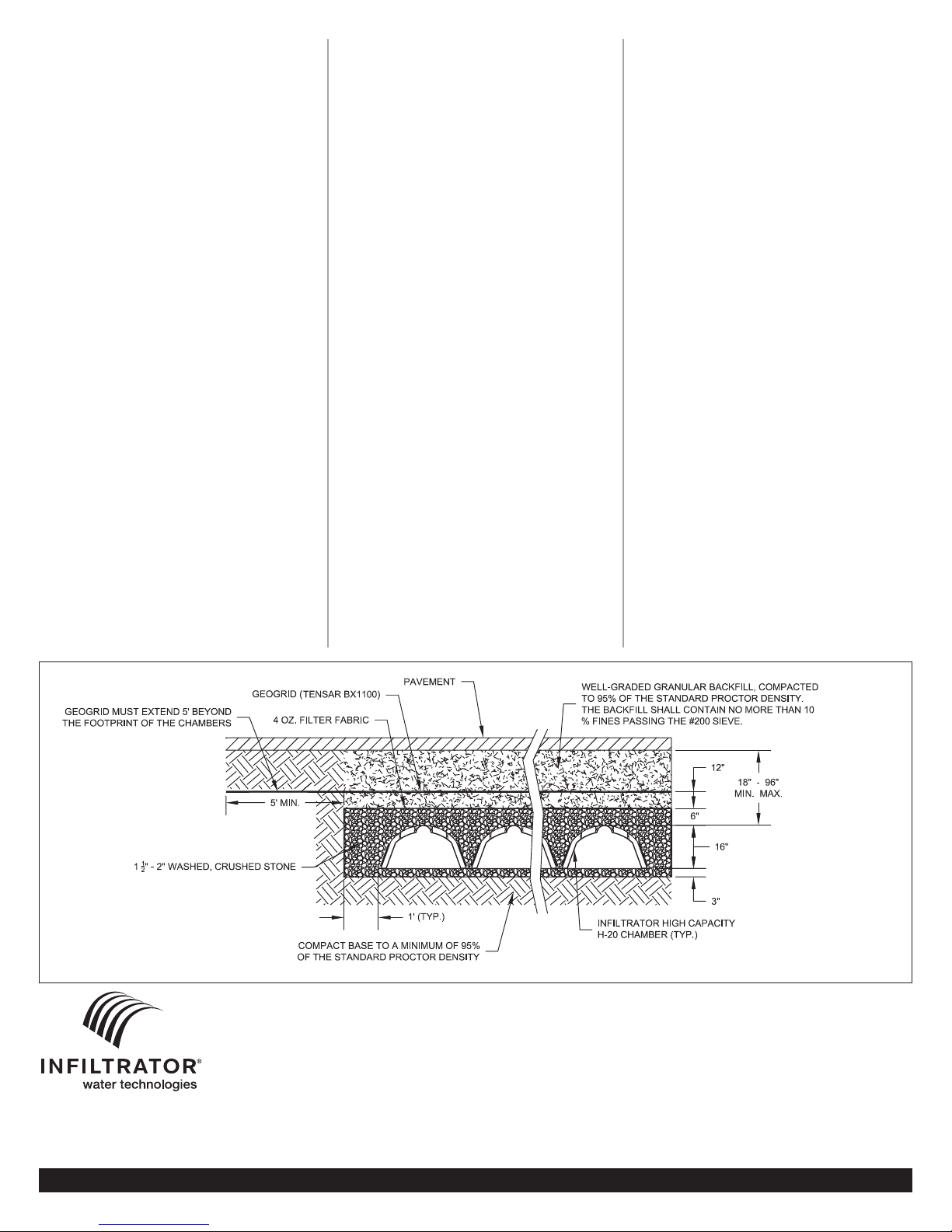
6. Place a minimum 3-inch layer of 1-1/2 to 2-inch
washed, crushed stone over the entire bottom
surface of the bed.
7. Compact the stone using at least two per-
pendicular passes of the vibratory roller with full
dynamic force applied to achieve a flat surface.
(Maximum gross vehicle weight of 12,000 lbs and a
maximum dynamic force of 20,000 lbs).
S
PECIFIED FILL MATERIAL
1. If a specified fill material is required, the fill
should be placed in lifts not exceeding 6 to 12
inches. The compaction of the fill should meet a
minimum density equivalent to 95 percent of the
soils Maximum Standard Proctor Density Value
(ASTM-D698).
2. The fill material, as a minimum, should meet
state and local criteria. However, sands with less
than 5% passing the U.S. #200 sieve are usually
acceptable provided their saturated hydraulic
conductivity (after compaction) is greater than
5 feet per day.
3. Compact the fill using a large piece of
machinery, (example: backhoe or bulldozer) or a
vibratory roller with its full dynamic force applied
to achieve a flat surface. (Maximum gross vehicle
Contact Infiltrator Water Technologies Inc. 1-800-221-4436 for additional technical and product information.
BEFORE YOU BEGIN
It is important to note that the High Capacity
H-20 chamber is the only Infiltrator chamber
warranted to be installed in traffic applications.
When installed using the following installation
instructions, the chambers can sustain vehicle
loads of up to 32,000 lbs (H-20) per axle.
Like non-traffic bed systems, the soil and site
conditions must be approved prior to installation.
Be sure that a thorough site evaluation is conducted
to determine the proper size and location of the
system before proceeding with the installation.
NOTE: The onsite system area is not to be used
as a staging area for construction equipment or
materials before or after construction of the
system. Temporary fencing, warning tape, and
appropriately located signs are commonly used
to prevent unauthorized traffic from damaging
sensitive soils.
NOTE: Due to the installation of stone on the
bottom of the bed, system sizing in parking
applications must not include any reduction
in the absorption area.
EXCAVATING AND PREPARING THE SITE
NOTE: Do not install system in wet conditions or
in overly moist soils, as this causes machinery to
smear the soil.
1. Locate all underground utilities.
2. Stake out the location of the bed and set the
elevation of the tank, pump chamber (if required),
Please note the following requirements to
assure proper construction:
• Contact local underground utility companies to
locate all utilities prior to construction.
• Check all chambers for shipping damage before
installation. Units that have been damaged
should not be installed. Contact Infiltrator Water
Technologies immediately upon discovery of any
damage.
• For a large bed that cannot be filled from the
sides, Infiltrator Water Technologies recommends
using a lightweight tracked vehicle (ground
pressure of tracks must not exceed 10 psi for 6” to
12” of cover. For examples of acceptable vehicles,
maximum wheel loads and maximum ground
pressure, please contact our Technical Assistance
department.
• ISI’s requirements for systems with a pavement
design (asphalt, concrete pavers, etc.): minimum
cover is 18” excluding pavement; maximum cover
is 96” including pavement. NOTE: Only the High
Capacity H-20 chamber is permitted for use in
traffic applications.
• A minimum of 6 inches of gravel must be
maintained beneath the tracks at all times.
• Washed, crushed stone must be between 1-1/2”
to 2” in size. Rounded or recycled stone is not
acceptable.
• A well-graded granular soil must be used for
backfill to maximum load carrying capacity.
• Sandy soils have special requirements.
• For gravity distribution, a distribution pipe is not
H-20 High Traffic
Installation Instructions
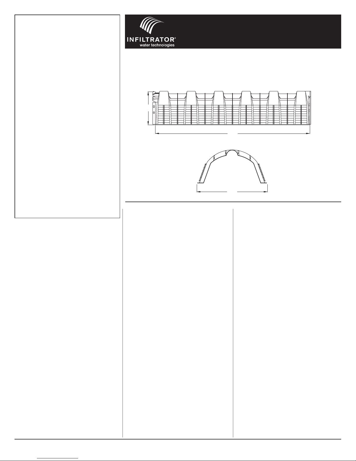
H-20 Chambers
It is important to note that the High Capacity H-20 chamber is the only Infiltrator cham-
ber warranted to be installed in traffic applications. When installed using the following
installation instructions, the chambers can sustain vehicle loads of up to 32,000 lbs
(H-20) per axle.
34"
75"
EFFECTIVE LENGTH
16"
weight of 12,000 lbs and a maximum dynamic
force of 20,000 lbs.)
4. After the fill has been placed and compacted,
verify the bottom of the bed is level using a transit,
laser or level.
PREPARING THE POSILOCK END PLATES
1. With a hole saw, cut an opening for the inlet
pipe using one of the pre-marked circles on the
end plate as a guide. Pre-marked circles allow for
4-inch corrugated, 4-inch SDR 35, 4-inch SCH 40
and 3-inch and 2-inch pressure dosing pipe.
NOTE: Pipe size may vary according to state/
county regulations or designer specifications.
2. Attach end plate to the inlet end of the
chamber by lining up the locking hubs wit the
corresponding chamber end. Apply firm pressure
to lock the hubs in place on one side of the
chamber and then the other.
NOTE: The end plate is clearly marked ‘Inlet Side
Toward Chamber’ to ensure proper installation.
3. At the inlet end of the end plate, insert the
appropriate diameter pipe into the previously
drilled hole. Fasten the pipe in place with a 2-inch
screw to secure it to the end plate. (End plates are
required only at the beginning and end of each
row of chambers. They are reversible to fit either
end of the chamber.)
NOTE: The end plate is designed so effluent will
flow in through the pipe corresponding inlet hole
and spill out of the opening on the other side.
When inserting the inlet pipe. it will only extend
into the end plate one inch before reaching a stop.