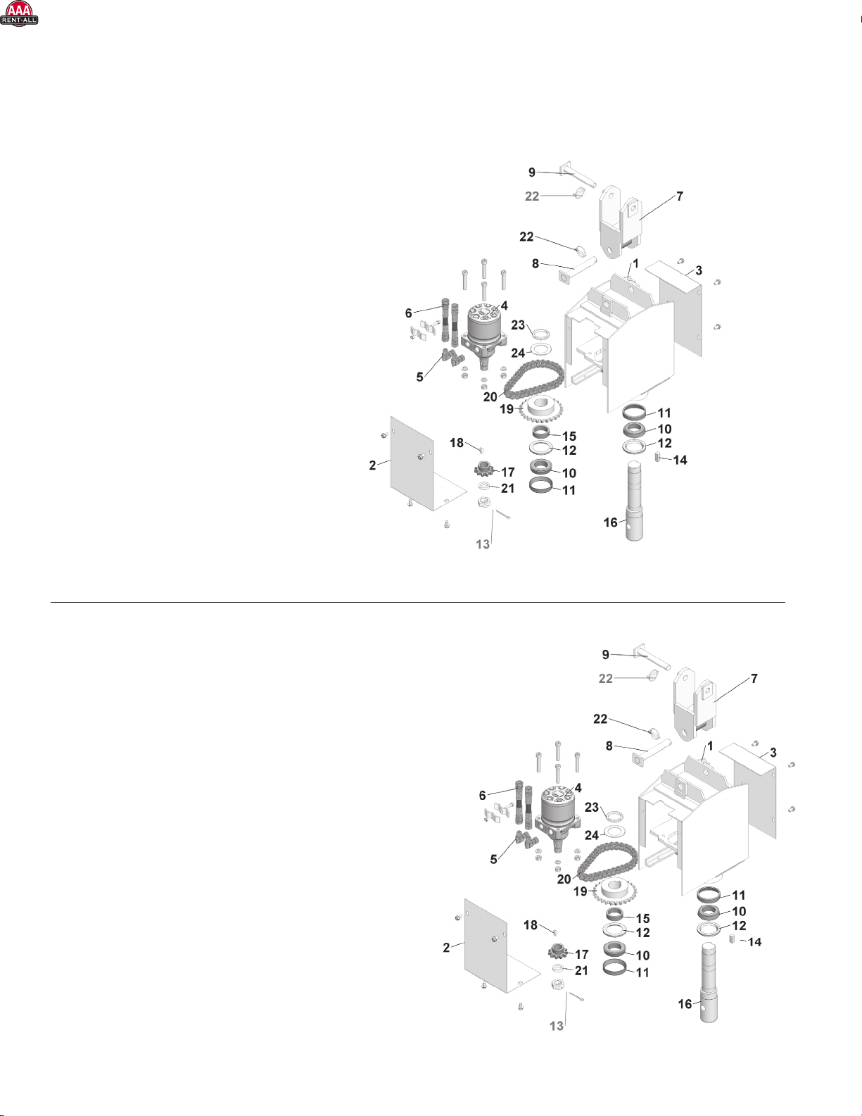
Lowe 500 Classic User manual

*Always follow manufacturer instructions*
*AAA Rent-All 225-291-1356*

*Always follow manufacturer instructions*
*AAA Rent-All 225-291-1356*

1
Equipment Attachments
18903 High Point Road
Viola, WI 54664
Table of Contents
I Warranty and Reservations
II Safety Information
III Machine Nomenclature
IV Machine Setup
V Mounting Instructions
VI Operation
VII Troubleshooting
VIII Maintenance
IX Unit Parts Diagrams
with Speed and Power Ratings
X Weights of Auger Installation
XI Performance Specs
www.loweman.com
For more information call:
North America Toll Free 1-800-356-9180 | Fax 608-538-3995
1-888-DIG-LOWE (344-5693)
1-608-538-4000
*Always follow manufacturer instructions*
*AAA Rent-All 225-291-1356*

2
WARRANTY
LOWE®Manufacturing Company, Incorporated, (LOWE®) is proud of its reputation for producing products with high
standards of quality and workmanship. When LOWE® products are used and maintained in the prescribed manner,
you can be assured they will provide reliable, productive service.
Period of Warranty: LOWE®auger drive units purchased and registered with LOWE®will be warranted against defects
in materials and workmanship for a period of two years from the date of purchase, subject to the exclusions noted
herein. Other LOWE®auger items are warranted for a period of one year. There is a FIVE (5) YEAR limited REPAIR or
REPLACE WARRANTY on the BP gearbox. Should anything go wrong with your new LOWE®BP and TJ gearbox that
is covered by warranty within that period, simply send it back to LOWE®and it will be repaired or replaced by trained
factory personnel. Replacement parts used in warranty repairs will be warranted for the balance of the applicable
warranty period.
Warranty Registration: To be eligible for warranty coverage, LOWE® product(s) must rst be registered with LOWE®.
A warranty registration form is provided in the Operator’s Manual. This form must be completed, signed, and mailed
to LOWE®by either the authorized selling dealer or the purchaser.
Customer’s Responsibility: Under the terms of this warranty, the customer will be responsible for ensuring the product
is properly operated and maintained as specied in the Operator’s Manual. The owner of the product shall give
notice to an authorized dealer of any and all apparent defects within ten (10) days of discovery and make the product
available for inspection and repairs at the dealer’s place of business. Dealers must contact LOWE®for authorization
of any warranty work.
The customer’s responsibilities include all costs of normal maintenance, replacement wear parts, non-warranty
repairs, accidents, collision damage, and other repairs resulting from abnormal strain, neglect, or abuse. Specic
examples include, but are not limited to, bending or prying with the product, failure to monitor wear, use of
contaminated hydraulic uid, excessive oil low or pressure, and operation with a broken or damaged part which
causes another part to fail. The customer is also responsible for incidental costs such as transportation due to failure.
If you have any specic questions on operation or maintenance, please contact your dealer or LOWE®for advice.
General Exclusions From Warranty: This warranty is not transferable and applies only to the original owner of
the equipment. It does not apply to products sold or used previously, products subject to misuse, service other
than normal, damage in transit or handling, normal wear, or products which in the opinion of LOWE®have had
unauthorized alterations or repair.
LOWE®will replace any warrantable parts with original LOWE®parts. LOWE®will not pay for unauthorized parts, nor
will it pay for the freight, excessive labor, travel time, or mileage connected with the replacement of warranty parts.
LOWE®will also not pay third party repair or replacement charges.
All defective parts against which warranty claims are made must be returned to LOWE®, freight prepaid, in
accordance with the LOWE® Ofcial Return Policy current at the time of the warranty claim. The hydraulic motor(s)
used in LOWE®products are warranted by the motor manufacturer and, in case of possible warranty failure, must be
returned to LOWE®or the nearest authorized hydraulic motor distributor for service. Any attempt by you, your dealer,
or another company to repair the motor will result in denial of warranty credit.
This warranty is in lieu of all other warranties, expressed or implied. Any claims for incidental or consequential
damages are hereby disclaimed by LOWE®and excluded from this warranty. LOWE®neither assumes nor authorizes
any person or company to assume for it any other obligations or liabilities in connection with its products.
This warranty gives you specic legal rights, and you may also have other rights which vary from state to state.
Model Number___________________________ Serial Number_____________________ Date Purchased ____________
Owner’s Name________________________________________________ E-mail __________________________________
Owner’s Address ______________________________________________________________________________________
Dealer’s Name _________________________________________________________________________________________
Dealer’s Address ______________________________________________________________________________________
City_________________________________________________________ State_________ Zip ________________________
Dealer’s Phone Number ________________________________________________________________________________
*Always follow manufacturer instructions*
*AAA Rent-All 225-291-1356*

3
3
The Safety Alert Symbol is used in this manual to highlight messages where your safety is involved.
When you see it, pay attention.
To emphasize special information, the words listed below carry specific meanings and should be carefully reviewed.
Danger .................. Denotes the most serious potential hazard(s).
Warning................. The personal safety of the operating personnel or other persons may be
involved. Disregarding this information could result in injury.
Caution.................. General reminders of good safety practices or to direct attention to
unsafe practices.
Note ...................... This is special information which may make operation of maintenance
easier, or make instructions more clear.
LOCATION OF SAFETY WARNINGS:
Replacement Safety Decals
Worn, damaged, or illegible labels should be replaced. New labels may be obtained from the manufacturer. Labels
are listed under specific part numbers and are included in the safety decal illustration.
Replacement Safety Shields
All worn, damaged, unusable, or missing safety shields should be replaced. New shields may be obtained from the
manufacturer. They are listed with a specific part number and are included in the exploded parts diagram.
Obligations and Usage:
This product is intended to be used only under the guidelines of this manual and relevant literature published by
LOWE®Manufacturing Company, Inc. It is the owner’s and/or operator’s obligation to ensure this product is operated
only for its intended uses. Operation contrary to guidelines set forth may cause premature breakage of the equipment
and create serious safety problems.
II
SAFETY INFORMATION
SD-5
WARNING
AVOID INJURY OR DEATH
ASD-1
BEFORE LEAVING LOADER • STOP AUGER ROTATION
• MOVE AUGER BACKWARDS AND PUT
COMPLETE LENGTH OF AUGER ON GROUND
• TURN OFF LOADER
FAILURE TO FOLLOW INSTRUCTIONS MAY CAUSE SERIOUS INJURY OR DEATH.
WARNING
AVOID INJURY OR DEATH
STAY AWAY FROM
ROTATING AUGER &
CUTTING HEAD
DO NOT WEAR LOOSE
FITTING CLOTHING
READ AND UNDERSTAND
OPERATOR’S MANUAL
BEFORE OPERATING OR
SERVICING MACHINE
CHECK FOR
UNDERGROUND
UTILITY LINES
STAND 10 FT. (3 m) OR MORE AWAY UNLESS OPERATING MACHINE
SD-5 ASD-1
SD-13 For boom
quick-tach
mountings
on excavators
and backhoes.
*Always follow manufacturer instructions*
*AAA Rent-All 225-291-1356*

4
4
Make certain that all power sources are disconnected before servicing!
1) _________ All nuts, bolts, and other hardware are tightened securely.
2) _________ All safety covers are secured in their proper positions.
3) _________ The two attachment hoses that run from the loader to the auger are secure and
are long enough to perform the full range of the auger’s capability. Such hoses
are usually not supplied with the drive unit.
4) _________ The auger mounting bracket is properly secured to the loader’s boom and all
levers and/or pins are properly locked in place.
5) _________ All hoses and fittings are properly tightened to avoid leaks.
6) _________ All controls operate freely and in the correct manner.
7) _________ The operator has been briefed on proper operation of the auger.
Warning: Do Not use a “Hole Top” cleaning device that extends past the normal working diameter of
the auger. Use of such a device greatly increases the chance of accidentally striking another person
or object, causing possible serious injury or equipment damage.
III
MACHINE NOMENCLATURE
IV
MACHINE SETUP
Your new auger drive unit comes completely assembled from the factory. However, some items may have loosened
or become lost during shipping or use. Because of the elements in which an auger operates, the following checklist
should be thoroughly completed each time before the machine is used.
Mounting Bracket
Auger Bit
Center Point
Teeth
Auger Pin
Auger Drive Unit
Connecting Link
Hose Kit
*Always follow manufacturer instructions*
*AAA Rent-All 225-291-1356*

5
5
V
MOUNTING INSTRUCTIONS
SKID LOADERS
1) Connect auger drive (item 2), connecting link (item 3), and mounting bracket (item 4).
2) Attach your choice of auger (item 1) to the shaft of the drive unit. Be sure auger pin is secured.
3) Connect mounting bracket to loader’s boom plate (item 5).
4) Secure all locking levers or pins in their proper fully locked position.
5) Connect two hydraulic hoses to the drive unit and then to the loader’s auxiliary hydraulic system via proper
quick couplers. (Is your hose length correct?)
6) You are now ready for operation.
CARRY POSITION: Roll back and lower lift arms until the lowest edge of the auger is 18 to 24 inches above the
ground. Transport the auger unit at a slow speed and without rapid side to side movement.
REMOVING THE AUGER SETUP:
1) Roll the loader arms back and lower lift arms until the end of the auger just touches the ground.
2) Stop the engine, disconnect the hydraulic hoses, and release locking levers or pins.
3) Start the engine and move the loader backward while lowering lift arms all the way down.
4) Tilt the loader boom plate forward.
NOTE: As the operator faces the mounted assembly the hoses should exit the top front of the drive unit. If mounted
improperly, damage to the hoses could occur.
Make sure the correct size pins are used to attach the various components, especially the auger.
WARNING: Avoid Tipping, Do Not Operate on Side Hills or Sloping Ground
Where the Machine Does Not Have a Firm, Stable Base.
Do Not Connect Hoses Until Assembly is Properly Mounted and Secured.
Never use a Bucket Clamping Device to Mount the Assembly to a Skid Loader.
Make Certain all Connecting Levers and/or Pins are Properly Locked in Place.
Carry the Assembly in Lowered Position at all Times. Avoid Excessive Swing.
Tether Auger with Locking Chain When Transporting on a Swinging Boom (such as a Backhoe).
Do Not Modify Equipment as Damage or Injury Could Occur.
Failure to Follow Directions May Result in Unstable Operation and/or Serious Injury.
BACKHOES (AND CRANES)
1) Following backhoe manufacturer’s instructions, remove the backhoe bucket (then disconnect bucket tilt cylinder
hydraulic hoses if on a backhoe).
2) Assemble drive unit, auger bit, and TBH mounting and then install TBH connecting link in the end of the backhoe
dipper arm.
3) Typically, you can “tap” into the bucket tilt cylinder hydraulic hoses for your hydraulic power. However, your
backhoe dealer is in the best position to advise you as to the best location to attach the auger’s hydraulic hoses.
4) It is important to follow the operating tips and safety instructions outlined in the previous section on Mounting for
Skid Loaders. Never allow the auger to swing excessively either during transport or drilling operations.
5) Carry auger as low as practical and curled as close to the loader as possible during transport on the job site.
Completely disconnect and store in a safe, secured position when loader is being transported from jobsite to
jobsite.
*Always follow manufacturer instructions*
*AAA Rent-All 225-291-1356*

6
6
FRONT END LOADERS
1) There are a number of methods for mounting, ranging from removal of the bucket and using a special mounting
bracket, to side mounting in a boom joint, to using a bucket clamping device. No matter what method is used, it is
important to securely mount the auger and make certain that all pins, levers, bolts, and other locking devices are
properly installed and maintained.
2) Your loader dealer is in the best position to advise you where to “tap” the system for your hydraulic power.
3) Follow the operating and safety steps outlined in the previous section on Mounting for Skid Loaders. Never allow
the auger to swing excessively during transport or drilling operations.
4) Carry auger as low as practical during transport on the jobsite. Completely disconnect and store in a safe, secured
position when the loader is being transported from jobsite to jobsite.
LOWE®Auger Drive Units are designed to be mounted on a machine with suitable hydraulic capacity. By
means of two hydraulic hoses attached to your machine’s hydraulic system, you are able to dig holes in a
variety of soil conditions.
The flow and pressure should be measured at the point where the unit is to be mounted. Most important
in a drilling operation is the amount of output torque your drive unit develops. As a general rule of thumb,
gallonage determines turning speed while hydraulic pressure determines torque. LOWE®augers are
designed with torque being the primary function for typical drilling applications.
DIGGING WITH THE AUGER
Caution: Do Not engage auger rotation unless the point of the auger cutting head is touching the ground. The auger
should turn in a clockwise direction for digging.
Operating an attachment auger can be made simpler by following a few simple guidelines:
1) Carry the auger low to the ground when traveling between drilling positions.
2) Position yourself and the loader as much as possible on the uphill side of the hole. Your machine balance and
down force will be greatly improved.
3) Do not try to run the loader arms, auger rotation, and other functions all at once. Instead, isolate each function.
On a skid loader, a typical method would be to:
a) Lift boom and then tilt loader bucket cylinder to full extension.
b) Position tip of auger at the center of the intended hole and touch the point to the ground.
c) Run loader at about 65 to 75 percent power and engage auger rotation.
d) Use loader boom pedal to gently push rotating auger into ground. Ease up on down force if rotation stops.
e) As the hole is being dug, periodically adjust loader’s position to assure a vertical hole. You may have to
monitor the position of the tilt arms if your loader has a self-leveling bucket feature.
f) Once the hole is dug, gently pull auger out of the ground with no rotation and shake the spoil dirt off.
If the auger is stuck, reverse rotation until it is free, then pull it out of the ground with no rotation.
g) Dip the auger back into the hole to pick up spoil dirt that may have fallen into the hole, then repeat step F.
h) Raise the auger out of the hole and roll tilt arms into low carry position. Watch for people and obstructions,
then go to the next hole site.
4) In hard or frozen ground it may be wise to slow the rotation speed to allow the teeth time to penetrate the soil.
5) Remember that torque and down force are the two most important items in digging hard-to-penetrate conditions.
Hard rock is best left to the premium high pressure truck drill rigs or to other methods of rock excavation.
VI
OPERATION
*Always follow manufacturer instructions*
*AAA Rent-All 225-291-1356*

7
7
(also see Checklist in Machine Setup Section)
WARNING: Diesel fuel or hydraulic fluid under pressure can penetrate the skin or damage eyes. Fluid
leaks under pressure may not be visible. Never use a bare hand to find leaks and always wear safety
goggles for eye protection. Such fluid, if injected into the skin, must be removed within a few hours by a
doctor familiar with this type of injury. Make certain power source is disconnected before servicing.
Shut off power, relieve pressure, and disconnect power source before performing maintenance.
VII
TROUBLESHOOTING
Symptom Possible Cause Action
Jerky Cold oil or air in lines
Loader hydraulic pump or system
Give time to warm up.
See loader’s manual.
Slow Restriction in lines, couplers,
or in loader’s hydraulic system
Worn, damaged, or insufficient
loader hydraulic pump
Loader oil filter
Check with pressure and flow gauge.
See loader dealer. Request flow (GPM)
and pressure (PSI) check.
Check for dirt and grime. See if filter is
installed correctly.
Insufficient digging
capacity
Hydraulic pump in loader or motor in auger
Excessive load
See your dealer. Request pressure check.
Reduce digging load because
load exceeds capacity of system.
Wrong direction Hoses not properly connected Re-install properly.
Oil leaks Hydraulic motor seals are worn or damaged
Loose fittings on hoses or motor
Hoses are loose or damaged
See dealer for replacement of seals.
Tighten or replace as required.
VIII
MAINTENANCE
Maintenance Required Length of Operation Type of Maintenance
Gear Box Lubricant 50 hours initially,
then once each year
Drain and replace gear oil. Use EP 80-90 wt. gear oil. Use 21 oz. in the BP-150, BP-210,
BP-230. Use 16 oz. in the TJ-100. Use 27 oz. in the A-275. Use 54 oz. in the A-400.
Motor Drive Chain 50 hours or as needed Lubricate. Chain should have about 1 inch (25.4 mm) of free play.
Auger Teeth As needed for wear Replace. Pay particular attention to outside teeth
Auger Center Point As needed for wear Replace.
Auger Attaching Pin As needed Check for bends, cracks, breaks, and visible wear. Replace if any of these
conditions are present.
Auger Driveshaft Before each use Check for bends, cracks, breaks, and visible wear. Replace if any of these
conditions are present.
Unit Mounting Pins (2) Before each use Check for bends, cracks, breaks, and visible wear. Replace if any of these
conditions are present.
NOTE: Use of a gear puller is highly recommended when removing a sprocket from a shaft.
Chain Lubricant can be any premium grade grease or commercial chain lube (motorcycle chain lubricant works
very well). The lubricant will do its best job when applied to a warm chain. Give the lubricant time to soak into the
working parts of the chain before resuming operation.
*Always follow manufacturer instructions*
*AAA Rent-All 225-291-1356*

8
8
IX
UNIT PARTS DIAGRAMS
with SPEED & POWER RATINGS
MODEL 750C Classic
Operational Range:
Oil Flow 6 to 20 GPM (23 to 76 Lpm)
Pressure 2,000 to 3,300 PSI (13,790 to 22,737 Kpa)
Digging Conditions Light
Typical Auger Sizes 6” (15 cm), 9” (23 cm), 12” (30 cm), 15” (38 cm), and 18” (46 cm) diameter
Ref. # Part # Description
1 75-001CL Housing
2 75-002A Front cover
4 75-004 Rear cover
7 MEL-12K Hydraulic motor
8 10-008E 90º elbow (2 Required)
9 10-009 Hose nipple and clamp assembly
11 10-112 Universal connecting link (includes 10-013S)
12 10-013CL Clevis pin
13 10-013S Clevis pin
14 10-368A Bearing cone (2 required)
15 10-362A Bearing cup (2 required)
16 10-25028 Seal (2 required)
17 N-10 Nut for output shaft
18 W-10 Washer for output shaft
19 10-15 Key for output shaft
20 TR-507 Spacer for output shaft
21 CR255-13 Round output shaft with nut, lockwasher and key
HE255-13 Hex output shaft with nut, lockwasher, and key
22 11-60T Motor sprocket (includes 10-17W key)
22a 10-17W Key for motor shaft
23 26-60 Driven sprocket (includes key)
24 34-60H Drive chain
25 10-14CL Motor shaft spacer
C-60H Chain connecting link
L-78 7/8” pin to attach auger to round (29/16”) shaft drive unit
L-50 3/4” pin to attach auger to hex (2”) shaft drive unit
SK-92 Seal kit for motor
MODEL 500CL
Operational Range:
Oil Flow 5 to 15 GPM (19 to 57 Lpm)
Pressure 1,700 to 3,300 PSI (11,720 to 22,737 Kpa)
Digging Conditions Light
Typical Auger Sizes 6” (15 cm), 9” (23 cm), 12” (30 cm), 15” (38 cm)
Ref. # Part # Description
1 75-001CL Housing
2 75-002A Front cover
4 75-004 Rear cover
7 MEL-12K Hydraulic motor
8 10-008E 90º elbow (2 Required)
9 10-009 Hose nipple and clamp assembly
11 10-112 Universal connecting link (includes 10-013S)
12 10-013CL Clevis pin
13 10-013S Clevis pin
14 10-368A Bearing cone (2 required)
15 10-362A Bearing cup (2 required)
16 10-25028 Seal (2 required)
17 N-10 Nut for output shaft
18 W-10 Washer for output shaft
19 10-15 Key for output shaft
20 TR-507 Spacer for output shaft
21 CR255-13 Round output shaft with nut, lockwasher and key
HE255-13 Hex output shaft with nut, lockwasher, and key
22 11-60T Motor sprocket (includes 10-17W key)
22a 10-17W Key for motor shaft
23 20-60 Driven sprocket (includes key)
24 30-60H Drive chain
25 10-14CL Motor shaft spacer
C-60H Chain connecting link
L-78 7/8” pin to attach auger to round (29/16”) shaft drive unit
L-50 3/4” pin to attach auger to hex (2”) shaft drive unit
SK-92 Seal kit for motor
MODEL 500 Classic
Operational Range:
Oil Flow 5 to 15 GPM (19 to 57 Lpm)
Pressure 1,700 to 3,300 PSI (11,720 to 22,737 Kpa)
Digging Conditions Light
Typical Auger Sizes 6” (15 cm), 9” (23 cm), 12” (30 cm), 15” (38 cm)
Ref. # Part # Description
1 75-001CL Housing
2 75-002A Front cover
3 75-004 Rear cover
4 MEL-12K Hydraulic motor
5 10-008E 90°elbow (2 Required)
6 10-009 Hose nipple and clamp assembly
7 10-112 Universal connecting link (Includes 10-013S)
8 10-013CL Clevis pin (Includes HANG-4)
9 10-013S Clevis pin (Includes HANG-4)
10 10-368A Bearing cone (2 Required)
11 10-362A Bearing cup (2 Required)
12 10-25028 Seal (2 Required)
13 N-12 Nut for motor shaft (Includes cotter key)
14 10-15 Key for output shaft
15 TR-507 Spacer for output shaft
16 CR255-13 Round output shaft
HE255-13 Hex output shaft
17 11-60T Motor sprocket (Includes 10-17W)
18 10-17W Key for motor shaft
19 20-60 Driven sprocket (Includes 10-15)
20 30-60H Drive chain
21 10-14 Motor shaft spacer
22 HANG-4 Lynch pin
23 N-10 Nut for output shaft
24 W-10 Lockwasher for output shaft
C-60H Chain connecting link
L-78 7/8” pin to attach auger to round (2 9/16”) shaft drive unit
L-50 1/2” pin to attach auger to hex (2”) shaft drive unit
SK-92 Seal kit for motor
MODEL 750 Classic
Operational Range:
Oil Flow 6 to 20 GPM (23 to 76 Lpm)
Pressure 2,000 to 3,300 PSI (13,790 to 22,737 Kpa)
Digging Conditions Light
Typical Auger Sizes 6” (15 cm), 9” (23 cm), 12” (30 cm), 15” (38 cm), and 18” (46 cm) diameter
Ref. # Part # Description
1 75-001CL Housing
2 75-002A Front cover
3 75-004 Rear cover
4 MEL-12K Hydraulic motor
5 10-008E 90°elbow (2 Required)
6 10-009 Hose nipple and clamp assembly
7 10-112 Universal connecting link (Includes 10-013S)
8 10-013CL Clevis pin (Includes HANG-4)
9 10-013S Clevis pin (Includes HANG-4)
10 10-368A Bearing cone (2 Required)
11 10-362A Bearing cup (2 Required)
12 10-25028 Seal (2 Required)
13 N-12 Nut for motor shaft (Includes cotter key)
14 10-15 Key for output shaft
15 TR-507 Spacer for output shaft
16 CR255-13 Round output shaft
HE255-13 Hex output shaft
17 11-60T Motor sprocket (Includes 10-17W)
18 10-17W Key for motor shaft
19 26-60 Driven sprocket (Includes 10-15)
20 34-60H Drive chain
21 10-14 Motor shaft spacer
22 HANG-4 Lynch pin
23 N-10 Nut for output shaft
24 W-10 Lockwasher for output shaft
C-60H Chain connecting link
L-78 7/8” pin to attach auger to round (2 9/16”) shaft drive unit
L-50 1/2” pin to attach auger to hex (2”) shaft drive unit
SK-92 Seal kit for motor
*Always follow manufacturer instructions*
*AAA Rent-All 225-291-1356*

9
9
MODELS 1200 Classic, 1650 Classic, 2175 Classic
Operational Range:
Oil Flow
1200 Classic 10-20 GPM (38 to 76 LPM)
1650 Classic 14-25 GPM (53 to 95 LPM)
2175 Classic 17-25 GPM (64 to 95 LPM)
Pressure 2,000 to 3,300 PSI (13,790 to 22,737 Kpa)
Digging Conditions Moderate to moderately heavy
Typical Auger Sizes
1200 Classic 6” (15 cm), 9” (23 cm), 12” (30 cm), 15” (38 cm), 18” (46 cm),
20” (51 cm), 24” (61 cm), and 30” (76 cm) diameter
1650 Classic 6” (15 cm), 9” (23 cm), 12” (30 cm), 15” (38 cm), 18” (46 cm),
20” (51 cm), 24” (61 cm), 30” (76 cm), and 36” (91 cm) diameter
2175 Classic 6” (15 cm), 9” (23 cm), 12” (30 cm), 15” (38 cm), 18” (46 cm),
20” (51 cm), 24” (61 cm), 30” (76 cm), and 36” (91 cm) diameter
Ref. # Part # Description
1 10-001CL Housing
2 10-002CL Front cover
4 10-004CL Rear cover
7 MEL-12K Hydraulic motor (1200 Classic)
MEL-18K Hydraulic motor (1650 Classic)
MEL-21K Hydraulic motor (2175 Classic)
8 10-008E 90º elbow (2 required)
9 10-009 Hose nipple and clamp assembly
11 10-112 Universal connecting link (includes 10-103S)
12 10-013CL Clevis pin
13 10-013S Clevis pin
14 10-368A Bearing cone (2 required)
15 10-362A Bearing cup (2 required)
16 10-25028 Seal (2 required)
17 N-10 Nut for output shaft
18 W-10 Washer for output shaft
19 10-15 Key for output shaft
20 TR-507B Spacer for output shaft
21 CR255-13 Round output shaft with nut, lockwasher and key
HE255-13 Hex output shaft with nut, lockwasher, and key
22 11-60T Motor sprocket (includes 10-17W key)
22a 10-17W Key for motor shaft
23 40-60 Driven sprocket (includes key)
24 46-60DBC Drive chain
25 10-14CL Motor shaft spacer
C-60DBC Chain connecting link
L-78 7/8” pin to attach auger to round (29/16”) shaft drive unit
L-50 3/4” pin to attach auger to hex (2”) shaft drive unit
SK-92 Seal kit for motor
MODELS BP-150, BP-210, and BP-230
Operational Range:
Oil Flow:
BP-150
BP-210
BP-230
Pressure Range:
10 to 20 GPM (38 to 76 Lpm)
15 to 30 GPM (57 to 114 Lpm)
18 to 30 GPM (68 to 114 Lpm)
2,000 to 3,300 PSI (13,790 to 22,737 Kpa)
Digging Conditions: Moderate to moderately heavy
Typical Auger Sizes:
BP-150 6” (15 cm), 9” (23 cm), 12” (30 cm), 15” (38 cm), 18” (46 cm),
20” (51 cm), 24” (61 cm), and 30” (76 cm) diameter
BP-210 6” (15 cm), 9” (23 cm), 12” (30 cm), 15” (38 cm), 18” (46 cm),
20” (51 cm), 24” (61 cm), 30” (76 cm), and 36” (91 cm) diameter
BP-230
6” (15 cm), 9” (23 cm), 12” (30 cm), 15” (38 cm), 18” (46 cm), 20” (51 cm),
24” (61 cm), 30” (76 cm), 36” (91 cm), 42” (107 cm), and 48” (122 cm) diameter
Ref. # Part # Description
1 10-013S Clevis pin to attach connecting link to machine
2 10-112 Standard connecting link (includes K-001)
3 SK-003 Clevis pin to attach auger drive unit to
connecting link (includes cotter key)
4 A-004 Drive unit housing with logo and safety labels
5 10-009 Hose nipple assembly
6 10-008E 90° elbows (2 required)
7 MEL-12S Hydraulic motor for A-165
7a MEL-18S Hydraulic motor for A-220
7b MEL-21S Hydraulic motor for A-245
8 ------------ 1/2x 11/2grade 5 SHCS with lockwashers (4 required)
9 K-005 Gasket
10 A-006H Gearbox hex shaft
A-006R Gearbox round shaft
11 ------------ 5/8x 2 grade 5 hexbolts with lockwashers (9 required)
12 SNT Serial number tag
Ref. # Part # Description
1 BP-112 Connecting Link 1
2 BP-113 Connecting Link Pin Assembly 1
3 BP-114 B.P. Unit Clevis Pin Assembly 1
4 BP-115 B.P. Unit Housing 1
5 10-009 Unit Motor Hose Assembly 1
6 10-008E Unit Motor Fitting 2
7 BP-118 B.P. Motor Bolt Assembly 4
8 MEL-12S Unit Motor Model BP-150 1
8 MEL-18S Unit Motor Model BP-210 1
8 MEL-21S Unit Motor Model BP-230 1
9 K-005 Motor Gasket 1
10 BPG-001 B.P. Top Cover 1
11 BPG-002 B.P. Top Cover bolt Assembly 12
13 BPG-004 B.P. Gear Set 1
15 BPG-006 B.P. Spacer 1
16 BPG-007 B.P. Shaft Nut 1
17 BPG-008 B.P. Shaft Lock Washer 1
18 BPG-014 B.P. Spacer
Ref. # Part # Description
19 BPG-009 B.P. Bearing Cone 2
20 BPG-010 B.P. Bearing Cup 2
21 BPG-011 B.P. Unit Hub 1
22 BPG-012 B.P. Housing Bolt Assembly 9
23 BPG-013 B.P. Shaft Seal 1
24 BPG-013H B.P. Hex Output Shaft 1
24 BPG-013R B.P. Round Output Shaft 1
L-78 7/8” pin to attach auger to
round (29/16”) shaft drive unit
L-50 3/4” pin to attach auger to hex
(2”) shaft drive unit
SK-92 Seal kit for motor
Gearbox Complete
10-24 BPG-006R Round Shaft
10-24 BPG-006H Hex Shaft
Ref. # Part # Description
110-001CL Housing
210-002CL Front cover
310-004CL Rear cover
4MEL-12K Hydraulic motor for 1200 Classic
MEL-18K Hydraulic motor for 1650 Classic
MEL-21K Hydraulic motor for 2175 Classic
510-008E 90°elbow (2 Required)
610-009 Hose nipple and clamp assembly
710-112 Universal connecting link (Includes 10-013S)
810-013CL Clevis pin (Includes HANG-4)
910-013S Clevis pin (Includes HANG-4)
10 10-368A Bearing cone (2 Required)
11 10-362A Bearing cup (2 Required)
12 10-25028 Seal (2 Required)
13 N-12 Nut for motor shaft (Includes cotter key)
14 10-15 Key for output shaft
15 TR-507B Spacer for output shaft
16 CR255-13 Round output shaft
HE255-13 Hex output shaft
17 11-60T Motor sprocket (Includes 10-17W)
18 10-17W Key for motor shaft
19 40-60 Driven sprocket (Includes 10-15)
20 46-60DBC Drive chain
21 10-14 Motor shaft spacer
22 HANG-4 Lynch pin
23 N-10 Nut for output shaft
24 W-10 Lockwasher for output shaft
C-60DBC Chain connecting link
L-78 7/8” pin to attach auger to round (2 9/16”) shaft drive unit
L-50 1/2” pin to attach auger to hex (2”) shaft drive unit
SK-92 Seal kit for motor
*Always follow manufacturer instructions*
*AAA Rent-All 225-291-1356*

10
10
MODEL A-275H
Operational Range:
Oil Flow: 15 to 42 GPM (57 to 159 Lpm)
Pressure Range: 2,000 to 4,200 PSI (13,790 to 28,958 kPa)
Digging Conditions: Moderate to moderately heavy
Typical Auger Size: 6” (15 cm), 9” (23 cm), 12” (30 cm), 15” (38 cm), 18” (46 cm),
20” (51 cm), 24” (61 cm), 30” (76 cm), and 36” (91 cm) diameter
Ref. # Part # Description
1 DM-013 Clevis pin to attach auger drive unit to connecting link
2 A-O11 Drive unit housing with logo and safety labels
3 L-large LOWE®logo
4 SD-5 Warning decal
5 SNT Serial number tag
6 10-008HP 90° elbow (2 required)
7 10-008TK Motor fitting (2 required)
8 TKL-15 Hydraulic motor
9 TK-005 Gasket
10 A-010H Gearbox 2” hex shaft
Model A-400H
Operational Range:
Oil Flow: 22 to 42 GPM (83 to 159 Lpm)
Pressure Range: 2,000 to 4,200 PSI (13,790 to 28,958 kPa)
Digging Conditions: Moderate to moderately heavy
Typical Auger Size: 6” (15 cm), 9” (23 cm), 12” (30 cm), 15” (38 cm), 18” (46 cm), 20” (51 cm),
24” (61 cm), 30” (76 cm), 36” (91 cm), 42” (107 cm), and 48” (122 cm) diameter
Ref. # Part # Description
1 SK-009 Clevis pin to attach auger drive unit to connecting link
2 A-008 Drive unit housing with logo and safety labels
3 L-large LOWE®logo
4 SD-5 Warning decal
5 SNT Serial number tag
7 10-008HP 90° elbow (2 required)
7 10-008TK Motor fitting (2 required)
8 TKL-30 Hydraulic motor
9 TK-005 Gasket
10 A-006-2.5H Gearbox 21/2” hex shaft
Ref. # Part # Description
1 TJ-113 Connecting link pin assembly
(Unit Clevis Pin)
2 TJ-112 Connecting link
(includes TJ-113)
3 TJ-114 Unit Pin Assembly
4 TJ-115 T.J. Unit housing
5 TJB-009 T.J. Cover Bolt Assembly
(2 Required)
6 TJB-010 T.J. Motor Bolt Assembly
(4 Required)
7 TJB-011 T.J. Top cover bolt Assembly
(16 Required)
8 TJB-012 T.J. Housing bolt Assembly
(6 Required)
9 TJ-002 T.J. Side Cover
Model TJ-100
Operational Range:
Oil Flow
TJ-100 5-15 (19-59 LPM)
Pressure 2,000 to 3,300 PSI (13,790 to 22.737 Kpa)
Digging Conditions Light to moderate
Typical Auger Sizes
TJ-100 6” (15 cm), 9” (23 cm), 12” (30 cm), 15” (38 cm), 18” (46 cm),
20” (51 cm), 24” (61 cm), 30” (76 cm), and 36” (91 cm) diameter
Ref. # Part # Description
10 MEL-9S Unit Motor model
11 TJ-014 Drain plug
12 10-009 Unit Motor Hose Assembly
13 10-008E 90° elbow
(2 Required)
14 TJ-004 T.J. Gear set/Ring Gear
15 TJ-006 T.J. Spacer
16 TJ-007 T.J. Shaft Nut
17 TJ-008 T.J. Shaft lock washer
18 TJ-006A T.J. Spacer
19 TJ-009 T.J. Bearing cone
(2 Required)
20 TJ-011 T.J. Unit Hub
21 TJ-010 T.J. Bearing cup
(2 Required)
22 TJ-013 T.J. Shaft seal
23 TJ-013H T.J. Hex output shaft
(Includes nut and lock washer)
23 TJ-013R T.J. Round output shaft
7-23 TJ-006R Round shaft Gearbox
7-23 TH-006H Hex shaft Gearbox
*Always follow manufacturer instructions*
*AAA Rent-All 225-291-1356*

11
X
WEIGHTS OF AUGER INSTALLATION
NOTE: Make certain auger assembly is used only on equipment that can safely handle the weight of all installed
items. Weights shown are estimated and do not include the weight of soil that may be on the auger bit.
XI
PERFORMANCE SPECIFICATIONS
Drive Unit Esmated Weight (lb/Kg)
500CL 85 / 39
750 Classic 170 / 77
1200 Classic 196 / 89
1650 Classic 198 / 90
2175 Classic 200 / 91
TJ-100 102 / 46
BP-150 164 / 74
BP-210 165 / 75
BP-230 166 / 75
A-275 270 / 122
A-400 390 / 177
Auger Bits (Standard Length)* Esmated Weight (lb/Kg)
SQ-6 56 / 25
SQ-9 83 / 38
SQ-12 110 / 50
SQ-15 145 / 66
SQ-18 163 / 74
SQ-20 186 / 84
SQ-24 203 / 92
SQ-30 260 / 118
SQ-36 340 / 154
SQ-42 439 / 199
SQ-48 480 / 218
Auger Bits cont. (Standard Length)* Esmated Weight (lb/Kg)
TSQ-18 117 / 53
TSQ-24 160 / 73
TSQ-30 270 / 122
TSQ-36 348 / 158
TSQ-42 430 / 948
TSQ-48 475 / 216
LP-6 50 / 23
LP-9 77 / 35
LP-12 108 / 49
LP-14/15 136 / 62
LP-18 119 / 54
LP-20 133 / 60
LP-24 178 / 81
LP-30 255 / 116
LP-36 286 / 130
Auger Mounng Brackets Esmated Weight (lb/Kg)
Typical Skid Steer Loader 145 / 66
Typical Backhoe Loader (TBH Link) 55 / 25
Tractor Front Loader (39LC Link) 51 / 23
Quick Connect Mount for Front Loaders 185 / 84
*Hex Hub - add 5 lb (2 Kg) to the weight of the auger bit.
FLOW
GPM / LPM 500CL 750CL 1200CL 1650CL 2175CL TJ-100 BP-150 BP-210 BP-230 A-275 A-400
6 / 22.7 56 44
8 / 30.3 75 64 59
10 / 37.9 94 80 52 73 51
12 / 45.4 113 97 63 88 61
14 / 53.0 132 113 74 51 103 71
16 / 60.6 129 84 58 82 55 57
18 / 68.1 145 95 65 54 93 62 50 65
20 / 75.7 161 106 73 60 103 68 54 73
22 / 83.3 80 67 76 60 79 42
24 / 90.8 88 73 82 64 86 45
26 / 98.4 89 70 94 49
28 / 106.0 97 75 101 53
30 / 113.6 104 81 108 57
32 / 121.1 116 60
34 / 128.7 123 64
36 / 136.3 130 68
38 / 143.8 137 71
40 / 151.4 145 76
42 / 159.0 79
SPEED IN RPM
DRIVE DRIVE
MODEL 2,000 2,500 3,000 3,500 4,000 MODEL 13,790 17,237 20,684 24,131 27,589
500CL 653 / 588 817 / 735 980 / 882 500CL 885 / 797 1,108 / 997 1,329/ 1,196
750CL 745 / 671 932 / 839 1,118 / 1,006 750CL 1,010 / 909 1,264 / 1,137 1,516 / 1,364
1200CL 1,150 / 1,035 1,437 / 1,293 1,724 / 1,552 1200CL 1,559 / 1,403 1,948 / 1,753 2,337 / 2,104
1650CL 1,652 / 1,487 2,062 / 1,856 2,478 / 2,230 1650CL 2,240 / 2,016 2,796 / 2,516 3,360 / 3,024
2175CL 1,992 / 1,793 2,490 / 2,241 2,989 / 2,690 2175CL 2,701 / 2,431 3,376 / 3,038 4,053 / 3,647
TJ-100 716 / 644 899 / 809 1,080 / 972 TJ-100 971 / 873 1,219 / 1,099 1,464 / 1,318
BP-150 1,190 / 1,071 1,486 / 1,337 1,783 / 1,604 BP-150 1,613 / 1,452 2,014 / 1,813 2,417 / 2,175
BP-210 1,708 / 1,537 2,135 / 1,921 2,562 / 2,306 BP-210 2,315 / 2,084 2,894 / 2,605 3,473 / 3,126
BP-230 1,999 / 1,799 2,497 / 2,247 2,998 / 2,696 BP-230 2,710 / 2,439 3,385 / 3,047 4,065 / 3,658
A-275 1,504 / 1,354 1,891 / 1,702 2,256 / 2,031 2,632 / 2,369 3,008 / 2,708 A-275 2,039 / 1,835 2,564 / 2,308 3,059 / 2,753 3,509 / 3,212 4,079 / 3,671
A-400 2,970 / 2,673 3,712 / 3,340 4,454 / 4,009 5,196 / 4,676 5,939 / 5,345 A-400 4,027 / 3,624 5,032 / 4,529 6,039 / 5,435 7,044 / 6,340 8,052 / 7,247
TORQUE - lb/ per PSI
(Theorecal / Near Actual)
TORQUE - Newton meters per Kpa
(Theorecal / Near Actual)
*Always follow manufacturer instructions*
*AAA Rent-All 225-291-1356*

*Always follow manufacturer instructions*
*AAA Rent-All 225-291-1356*

*Always follow manufacturer instructions*
*AAA Rent-All 225-291-1356*

*Always follow manufacturer instructions*
*AAA Rent-All 225-291-1356*
This manual suits for next models
10
Table of contents
Popular Lawn And Garden Equipment manuals by other brands

Holman
Holman RGB1505 instruction manual

GÜDE
GÜDE 95504 Translation of the original instructions

Echo
Echo 99944200418 installation instructions

FLORABEST
FLORABEST FLV 1200 A1 translation of original operation manual

Gardeners
Gardeners Demeter Metal Composter Assembly

Craftsman
Craftsman 358.795660 Operator's manual