LOYTEC L-MBUS20 User manual

L-MBUS20/L-MBUS80
M-Bus Level Converter
User Manual
LOYTEC electronics GmbH

Contact
LOYTEC
Blumengasse 35
A-1170 Vienna
AUSTRIA/EUROPE
http://www.loytec.com
Version 1.0
Document №88077901
LOYTEC MAKES AND YOU RECEIVE NO WARRANTIES OR CONDITIONS,
EXPRESS, IMPLIED, STATUTORY OR IN ANY COMMUNICATION WITH YOU,
AND
LOYTEC SPECIFICALLY DISCLAIMS ANY IMPLIED WARRANTY OF
MERCHANTABILITY OR FITNESS FOR A PARTICULAR PURPOSE. THIS
PRODUCT IS NOT DESIGNED OR INTENDED FOR USE IN EQUIPMENT
INTENDED FOR SURGICAL IMPLANT INTO THE BODY OR OTHER
APPLICATIONS INTENDED TO SUPPORT OR SUSTAIN LIFE, FOR USE IN
FLIGHT CONTROL OR ENGINE CONTROL EQUIPMENT WITHIN AN
AIRCRAFT, OR FOR ANY OTHER APPLICATION IN WHICH IN THE FAILURE
OF SUCH PRODUCT COULD CREATE A SITUATION IN WHICH PERSONAL
INJURY OR DEATH MAY OCCUR.
No part of this publication may be reproduced, stored in a retrieval system, or transmitted,
in
any form or by any means, electronic, mechanical, photocopying, recording, or otherwise,
without the prior written permission of LOYTEC.
L-MBUSis trademark of LOYTEC electronics GmbH.

L-MBUSxx User Manual 3 LOYTEC
Version 1.0 LOYTEC electronics GmbH
Contents
1Introduction..................................................................................................5
1.1 Overview..............................................................................................................5
1.2 Scope.....................................................................................................................5
2Hardware Installation..................................................................................6
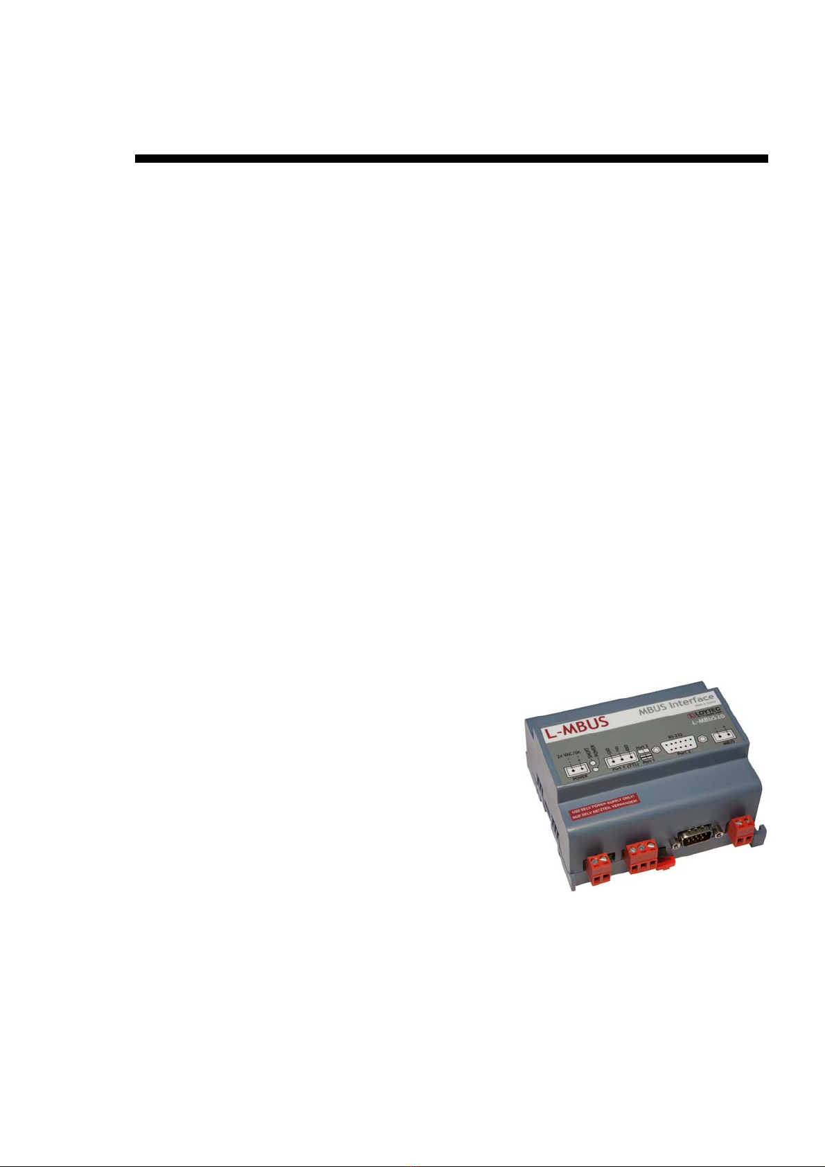
2.1 Enclosure .............................................................................................................6
2.2 Product Label......................................................................................................7
2.3 Mounting..............................................................................................................7
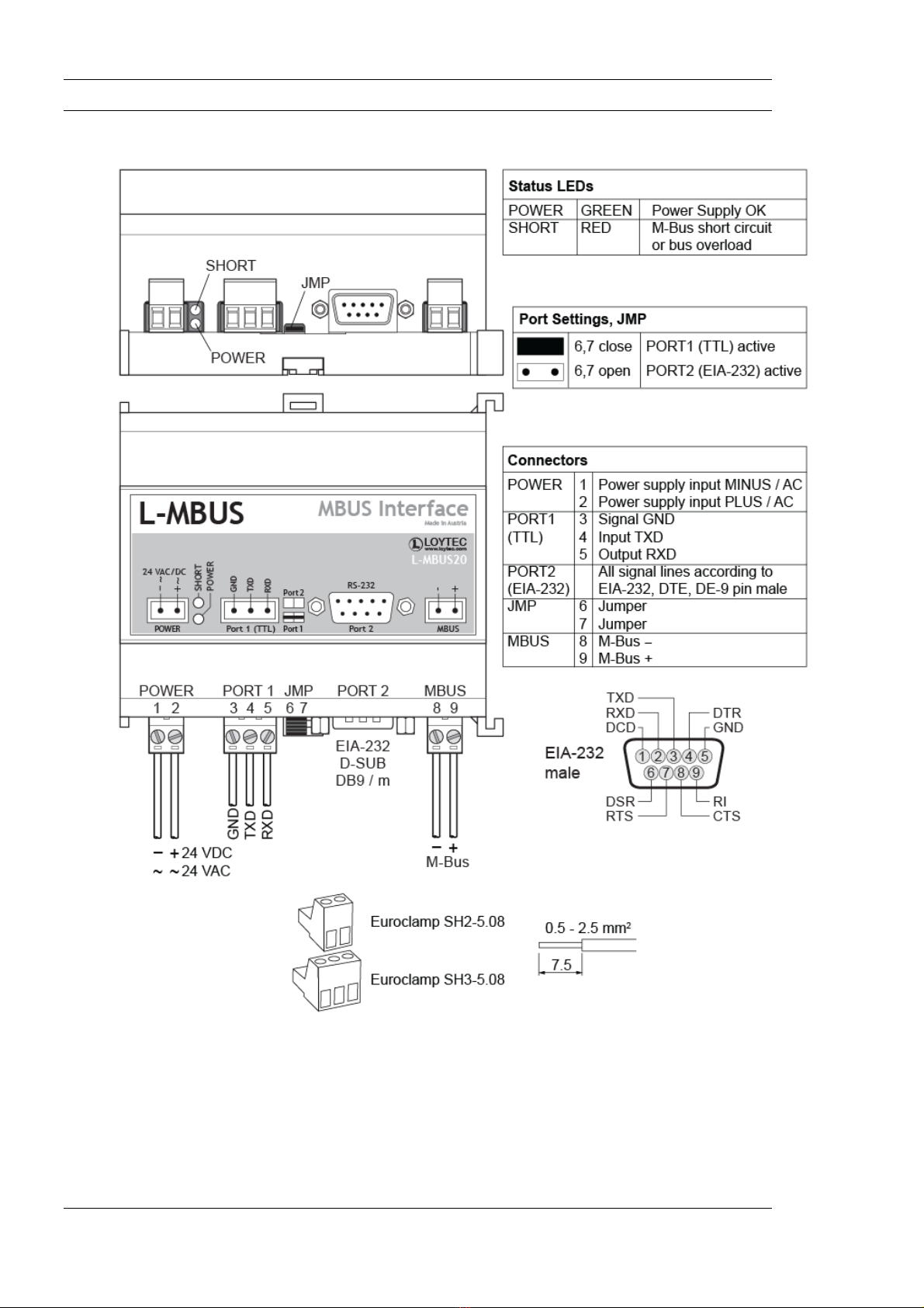
2.4 Connectors, LEDs, Wiring.................................................................................8
2.5 LED signals..........................................................................................................9
2.5.1 Power LED ................................................................................................9
2.5.2 Short LED..................................................................................................9
2.6 Operating Mode..................................................................................................9
2.7 Terminal Layout and Power Supply.................................................................9
2.8 Wiring ................................................................................................................10
2.8.1 Wiring of TTL level interface Port 1 .......................................................10
2.8.2 Wiring of RS-232 level interface Port 2 ..................................................10
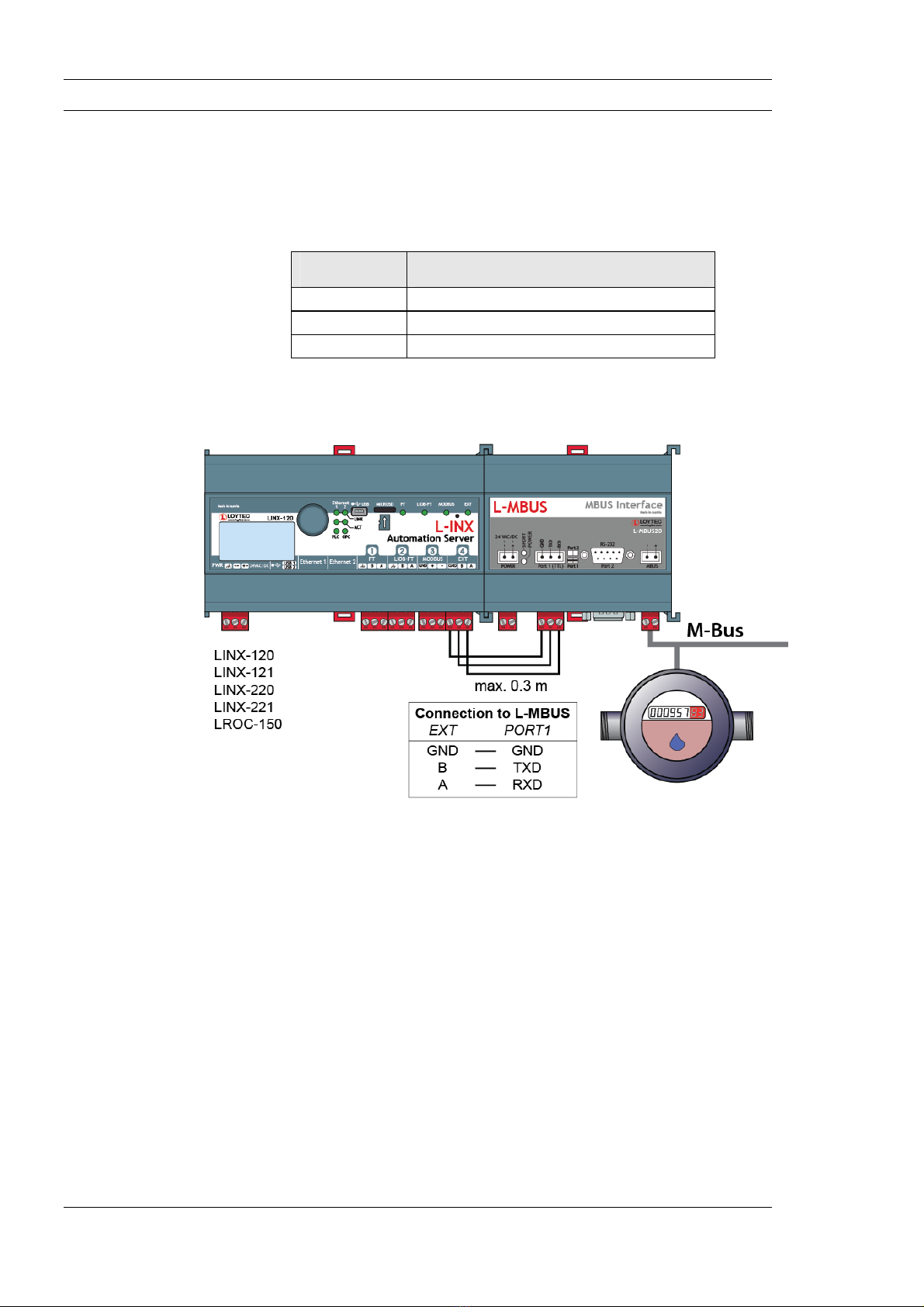
2.8.3 Wiring M-Bus network............................................................................11
3Troubleshooting..........................................................................................13
3.1 Technical Support.............................................................................................13
4Specifications ..............................................................................................14
4.1 L-MBUSxx.........................................................................................................14
4.1.1 Physical and Electrical Specifications ..................................................... 14
5Order Information .....................................................................................15
5.1 L-MBUSxx.........................................................................................................15
6Revision History .........................................................................................16

L-MBUSxx User Manual 4 LOYTEC
Version 1.0 LOYTEC electronics GmbH
Abbreviations
M-Bus................................. Meter-Bus
RXD ................................... Receive Data
TXD.................................... Transmit Data

L-MBUSxx User Manual 5 LOYTEC
1 Introduction
1.1 Overview
The L-MBUS20 and L-MBSU80 are level converters between RS-232 level or TTL level
UART signals and an M-Bus network. The L-MBUS must be connected to an M-Bus
master interface. The L-MBUS20 can read up to 20 M-Bus slave devices and the
L-MBUS80 can read up to 80 M-Bus slave devices.
1.2 Scope
This document covers L-MBUS devices.
Version 1.0 LOYTEC electronics GmbH

L-MBUSxx User Manual 7 LOYTEC
2.2 Product Label
The product label on the side of the L-MBUSxx contains the following information (see
Figure 1):
L-MBUS20 or L-MBUS80 Order Number,
Serial Number with bar-code (SER#),
Production Date.
Unless stated otherwise, all bar codes are encoded using “Code 128”. An additional label is
also supplied with the L-MBUSxx for documentation purposes.
2.3 Mounting
The device comes prepared for mounting on DIN rails following DIN 50 022. The device
can be mounted in any position. However, an installation place with proper airflow must be
selected to ensure that the L-MBUSxx’s temperature does not exceed the specified range
(see Chapter 4).
Version 1.0 LOYTEC electronics GmbH

L-MBUSxx User Manual 8 LOYTEC
2.4 Connectors, LEDs, Wiring
Figure 2: L-MBUSxx connectors, LEDs, wiring
Version 1.0 LOYTEC electronics GmbH

L-MBUSxx User Manual 9 LOYTEC
2.5 LED signals
2.5.1 Power LED
The L-MBUSXX power LED lights up green when power is supplied to terminals
“POWER”.
2.5.2 Short LED
The L-MBUSXX is equipped with a red Short LED (see Figure 2). This LED is normally
off.
If the M-Bus is shorted or overloaded, the Short LED lights up red.
2.6 Operating Mode
The L-MBUSxx level converter can be connected to
a) RS-232 level UART interface
b) TTL level UART interface
The selection is done with the jumper JMP according to the table below.
Jumper JMP Function
Installed TTL level interface is active
Not Installed RS-232 level interface is active
Table 1: L-MBUSxx jumper setting for operating mode selection.
2.7 Terminal Layout and Power Supply
The L-MBUSXX provides pluggable screw terminals to connect to the network as well as
to the power supply. The screw terminals can be used for wires of a maximum thickness of
1.5 mm2/AWG12. The device can either be DC or AC powered. The connectors are shown
in Figure 2
Terminal Function
1,2 Power Supply 24 VDC or 24 VAC
3,4,5 TTL level UART interface to M-Bus master
8,9 M-Bus network connector
PORT2 RS-232 level UART interface to M-Bus master
Table 2: L-MBUSxx Terminals
Version 1.0 LOYTEC electronics GmbH

L-MBUSxx User Manual 10 LOYTEC
2.8 Wiring
2.8.1 Wiring of TTL level interface Port 1
If the L-MBUSxx is connected to an M-Bus master with TTL level interface e.g. LINX-
120, LINX-121, LINX-220, LINX-221, LROC-150, the wiring must be done as shown
below. Make sure jumper JMP is installed. The maximum cable length is 0.3 m.
PORT 1 Function
3 TTL level GND
4 TTL level TXD (input)
5 TTL level RXD (output)
Table 3: Connecting the L-MBUSxx via TTL level UART interface Port 1.
Figure 3: Wiring of L-MBUSxx with TTL level interface M-Bus master.
2.8.2 Wiring of RS-232 level interface Port 2
If the L-MBUSxx is connected to an M-Bus master with RS-232 level interface the wiring
must be done as shown below. A null-modem cable is required to connect the L-MBUSxx
to a PC or a LINX-100, LINX-101, LINX-110, LINX-111, LINX-200, LINX-201,
LINX-210, LINX-211. Make sure jumper JMP is removed. The maximum cable length is
1 m.
Version 1.0 LOYTEC electronics GmbH

L-MBUSxx User Manual 11 LOYTEC
Figure 4: Connecting the L-MBUSxx via RS-232 level UART interface Port 2.
When the L-MBUSxx is used with other M-Bus master devices other than the LOYTEC LINX or LROC devices
please make sure that the M-Bus master device will ignore received characters while it transmits M-Bus data
packets. The L-MBUS might send out valid or invalid characters on Port2 while it transmits M-Bus data packets
on the M-Bus port.
2.8.3 Wiring M-Bus network
Depending on the bitrate the following total length of network wiring is possible.
Bitrate Total Wiring Length in [m]
300 < 12000 m
2400 < 4000 m
9600 < 1000 m
Table 4: M-Bus total wiring length.
Since the quiescent current of M-Bus devices generate a voltage drop along the M-Bus
cable the maximum distance from an M-Bus slave device to the L-MBUSxx is limited as
follows for a JYSTY nx2x0.8 cable.
Version 1.0 LOYTEC electronics GmbH

L-MBUSxx User Manual 12 LOYTEC
Number of devices on M-Bus network Max. distance in [m]
5 6500 m
10 5000 m
20 3100 m
80 750 m
Table 5: M-Bus maximum distance for M-Bus slave from L-MBUSxx on JYSTY nx2x0.8.
The polarity is irrelevant for M-Bus networks.
Version 1.0 LOYTEC electronics GmbH

L-MBUSxx User Manual 13 LOYTEC
3 Troubleshooting
3.1 Technical Support
LOYTEC offers free telephone and e-mail support for our L-MBUSXX product. If none of
the above descriptions solves your specific problem please contact us at the following
address:
LOYTEC electronics GmbH
Blumengasse 35
A-1170 Vienna
Austria / Europe
e-mail : support@loytec.com
web : http://www.loytec.com
tel : +43/1/4020805-200
fax : +43/1/402080599
or
LOYTEC Americas Inc.
11258 Goodnight Lane
Suite 101
Dallas, Texas 75229
USA
Email: support@loytec-americas.com
web: http://www.loytec-americas.com
tel: +1/512/402 5319
fax: +1/972/243 6886
Version 1.0 LOYTEC electronics GmbH

L-MBUSxx User Manual 14 LOYTEC
4 Specifications
4.1 L-MBUSxx
4.1.1 Physical and Electrical Specifications
Characteristics Value
Supply Voltage 24 VDC or 24 VAC ±10%
Power Consumption L-MBUS20: 0.45 A @ 24 VDC
L-MBUS80: 0.65 A @ 24 VDC
Max number of M-Bus slaves L-MBUS20: 20
L-MBUS80: 80
In rush current up to 950 mA @ 24 VDC
Operating Temperature (ambient) 0 C to + 50 C
Humidity (non condensing)
operating
10 to 90% RH @ 50C
Humidity (non condensing) storage 90% RH @ 50C
Enclosure Installation enclosure 6 TE, DIN 43 880
Environmental Protection IP 40 (enclosure); IP 20 (screw terminals)
Installation DIN rail mounting (EN 50 022) or wall mounting with
optional DIN rail
Supported bit rates 300 bits/s – 9600 bits/s
Bus quiescent current L-MBUS20: 0-30 mA
L-MBUS80: 0-120 mA
Resistance to short circuit on
M-Bus
continuous
Over current protection
Level:
Minimum switch off time:
L-MBUS20: 190 mA
L-MBUS80: 310 mA
100 ms
Bus voltage when idle 35 V +/-5%
Table 6 Physical and Electrical Characteristics.
Version 1.0 LOYTEC electronics GmbH

L-MBUSxx User Manual 15 LOYTEC
5 Order Information
5.1 L-MBUSxx
Currently there are 2 product versions available.
Model Description
L-MBUS20 M-Bus level converter for up to 20 M-Bus slave devices.
L-MBUS80 M-Bus level converter for up to 80 M-Bus slave devices.
Table 7 Order Information
Version 1.0 LOYTEC electronics GmbH

L-MBUSxx User Manual 16 LOYTEC
Version 1.0 LOYTEC electronics GmbH
6 Revision History
Date Version Author Description
2010-05-10 1.0 DL Initial revision V1.0
This manual suits for next models
1
Table of contents
Popular Media Converter manuals by other brands

Moxa Technologies
Moxa Technologies TCF-90 Quick installation guide

GHM Greisinger
GHM Greisinger USB 3100 N Installation and operating manual

Vertiv
Vertiv NetSure IPE Series Installation and user manual

Kramer
Kramer KDS-EN6 user manual

Arcam
Arcam RDAC - Service manual

Comtech EF Data
Comtech EF Data MBT-5003 Installation and operation manual