LSI LASTEM EXP830 User manual

Guida rapida sensore EXP830
INSTUM_02077 Agg. 18/05/2021 Pag. 1/ 2
1. Introduzione
EXP830 è un sensore per il monitoraggio della temperatura nei
cumuli di compost durante il processo di biossidazione o nei biofil-
tri o di qualsiasi altro materiale aggressivo che si trovi
nell’impianto di gestione del rifiuto.
I messaggi radio trasmessi da questo sensore sono ricevibili dai
data logger E-Log, M-Log ed ALIEM tramite il ricevitore radio
EXP301. I ripetitori radio EXP401 possono essere utilizzati (fino a 6
in cascata) qualora il sensore sia “fuori portata” dal ricevitore.
É possibile ottenere segnali in corrente 4÷20 mA dai sensori utiliz-
zando un convertitore radio EXP302.
2. Configurazione E-Log/M-Log/ALIEM
Tramite il programma 3DOM modificare la configurazione del data
logger come segue:
➢Aggiungere il sensore EXP830 dalla libreria dei sensori.
➢Impostare come Id sensore l’identificativo del sensore. L’id è
riportato sulla scatola del sensore.
➢[Facoltativo] Se si utilizzano più sensori personalizzare il
nome delle misure per distinguere le une dalle altre.
Per maggiori informazioni fare riferimento ai manuali del data
logger e di 3DOM.
3. Posizionamento
Il sensore va collocato all’interno del materiale da monitorare pre-
feribilmente in posizione verticale. Per le operazioni di inserimen-
to nel cumulo o rimozione utilizzare le apposite manopole DYA500
da montare sulla parte superiore dell’asta. Si raccomanda di non
superare l’altezza del nastro catarifrangente. Nel caso l’eccessiva
consistenza del materiale renda difficoltoso l’inserimento del sen-
sore è consigliabile ricavare una sede dove infilare il sensore tra-
mite altre attrezzature. Non utilizzare altri apparati meccanici, se
non quelli fornite a corredo, per forzare l’inserimento della sonda
nel cumulo.
Al termine delle operazioni di posizionamento è possibile sfilare le
manopole DYA500.
Fig. 1 –Posizionamento sensori.
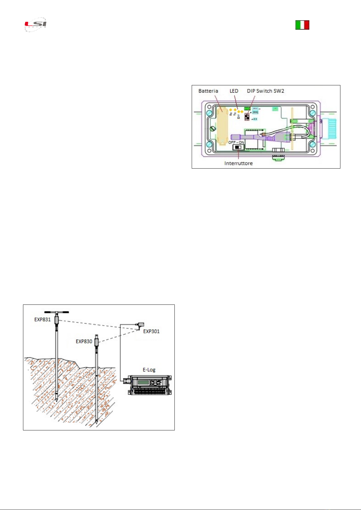
Accendere il sensore. L’interruttore è posizionato all’interno della
scatola (Fig. 2).
4. Manutenzione
Il sensore EXP830 è uno strumento di precisione. È in grado di
funzionare a lungo senza particolari problemi o necessità di manu-
tenzione. Sostituire la batteria situata all’interno della scatola (Fig.
2) quando la percentuale di carica è prossima allo zero.
Fig. 2 –Scatola sensore, vista interna.
5. Diagnostica
Tutte le misure di tutti i sensori radio sono in errore
È probabile che il problema sia dovuto al ricevitore. Controllare
alimentazione e connessione al data logger.
Tutte le misure di alcuni sensori radio sono in errore
È probabile che il problema sia dovuto al ripetitore. Controllarne
l’alimentazione.
Tutte le misure di un solo sensore radio sono in errore
È probabile che il problema sia dovuto al sensore. Aprire la sca-
tola e verificare che l’interruttore sia in posizione ON, spostare il
DIP switch 1 di SW2 su ON (trasmissione ogni 3-4 s) e verificare
che il led TX si accenda frequentemente. Se non si accende, la
batteria potrebbe essere completamente scarica (in tal caso so-
stituirla –ricordarsi di riposizionare il DIP switch 1 a OFF) oppu-
re ciò è dovuto ad un guasto del sensore.
Alcune misure di uno o più sensori radio sono in errore
Potrebbe essere un problema del sensore (o di un sensore ad
esso collegato).
5.1. Segnalazioni luminose
Sulla scheda elettronica posta all’interno del contenitore sono
presenti alcuni indicatori luminosi (LED) aventi questo significato
(in riferimento a Fig. 2):
➢Tx: si accende (per brevissimi istanti) durante la trasmissione
radio
➢Rx: si accende durante la ricezione di messaggi (solo per ope-
razioni di configurazione destinate a personale tecnico LSI
LASTEM)
➢Err: indica una condizione anomala di funzionamento. Il tipo
di segnalazione può essere:
oSingolo lampeggio molto rapido (100 ms): condizione di at-
tenzione (in uso la rata di campionamento/trasmissione ra-
pida; oppure problemi sporadici di campionamento; oppure
altri errori non critici); in questa condizione il sensore rima-
ne comunque operativo.
oDoppio lampeggio o singolo lampeggio prolungato (300 ms):
condizione di errore grave (errore HW; oppure configura-
zione errata); in questa condizione il sensore non funziona
correttamente e va quindi riparato o riprogrammato.

Guida rapida sensore EXP830
INSTUM_02077 Agg. 18/05/2021 Pag. 2/ 2
6. Caratteristiche tecniche
Misure
Nome misura
Scala
Accuratezza
Risoluzione
Temperatura 1
0÷100 °C
±0,5 °C @ Tamb=25 °C
0,03 °C
Temperatura 2
0÷100 °C
±0,5 °C @ Tamb=25 °C
0,03 °C
Batteria (tensione)
3÷4 V
±0,05 V
0,01 V
Batteria (livello)
0÷100 %
-
1 %
Elaborazione
Rata campionamento
10’
Dati trasmessi
istantaneo (ultimo campionamento)
Radio
Frequenza
869,450 MHz
Modulazione
GFSK/4GFSK
Potenza Tx
25 ±3 mW
Sensitività Rx
-104 ±2 dBm
Portata
600 m
Baud rate
9600 bps
Alimentazione
Batteria
3,6 V litio, tipo AA
Consumo
< 10 µW in stand-by, 250 mW in trasmissione
Durata stimata
oltre 2 anni
7. Smaltimento
Questo prodotto è un dispositivo ad alto contenuto elet-
tronico. In ottemperanza alle normative di protezione am-
bientale e recupero, LSI LASTEM raccomanda di trattare il prodot-
to come rifiuto di apparecchiatura elettrica ed elettronica (RAEE).
La sua raccolta a fine vita deve essere separata da rifiuti di altro
genere.
LSI LASTEM risponde della conformità della filiera di produzione,
vendita e smaltimento del prodotto, assicurando i diritti
dell’utente. Lo smaltimento abusivo di questo prodotto provoca
sanzioni a norma di legge.
8. Supporto tecnico
LSI LASTEM offre il proprio servizio di assistenza all’indirizzo
di assistenza tecnica scaricabile dal sito www.lsi-lastem.com.
Per ulteriori informazioni si faccia riferimento ai seguenti recapiti:
-Telefono: +39 02 95.414.1 (centralino)
-Indirizzo: Via ex S.P. 161 –Dosso n. 9
20049 Settala, Milano
-Sito web: www.lsi-lastem.com
-Servizio commerciale: [email protected]
-Servizi post-vendita: [email protected]
Copyright
Le informazioni contenute nel presente manuale sono soggette a modifi-
che senza preavviso. Nessuna parte di questo manuale può essere ripro-
dotta in qualsiasi forma o mezzo elettronico o meccanico, per alcun uso,
senza il permesso scritto di LSI LASTEM.
LSI LASTEM si riserva il diritto di intervenire sul prodotto, senza l’obbligo di
aggiornare tempestivamente questo documento.
Copyright 2015-2016 LSI LASTEM. Tutti i diritti riservati.

Quick start sensor EXP830
INSTUM_02077 Upd. 18/05/2021 Page 1 / 2
1. Introduction
EXP830 is a sensor for monitoring of temperature inside compost
heaps during bioxidation process or biofilter or any other aggres-
sive material in the waste management plant.
This sensor transmits radio messages receivable with E-Log, M-Log
and ALIEM data logger using a radio receiver EXP301. If the sensor
is outside the radio range of the receiver, it is possible to use up
to 6 cascading repeaters EXP401. It is possible to obtain 4÷20 mA
current signals from the sensors using a radio converter EXP302.
2. E-Log/M-Log/ALIEM configuration
Using the software 3DOM modify the data logger configuration as
follows:
➢Add the sensor EXP830 from the sensors library.
➢Set as Probe id the id of the sensor. It is reported on the
sensor case.
➢[Optional] If you are using two or more sensors, you can
customize the name of the measures to distinguish them
from each other.
For more information, refer to the manuals of the data logger and
3DOM.
3. Positioning
The sensor must be positioned in piles of composting materials
preferably in a vertical position. For insertion (and unsheathing)
operation use the appropriate handles DYA500 to be mounted on
top of the rod. It is recommended not to exceed the height of the
reflective tape. Where the consistency of the compost does not
allow direct insertion, dig a shaft into the pile to create a seat for
the sensor. Do not use mechanical equipment to force the probe
insertion in the compost.
Remove the handles DYA500 once the sensor is positioned.
Fig. 3 - Sensors positioning.
Turn on the sensor. The switch is positioned inside the case (Fig.
4).
4. Maintenance
Sensor EXP830 is a precision instrument. It can operate for a long
time without any significant problems or maintenance require-
ments. Replace the battery inside the case (Fig. 4) when indicated
charge level is near to zero.
Fig. 4 - Sensor case, inside view.
5. Diagnostics
All measurements from all radio sensors are in error
It is likely that the problem is due to the receiver. Check the
power supply and the connection to the data logger.
All measurements of some radio sensors are in error
It is likely that the problem is due to the repeater. Check its
power supply.
All measurements of one radio sensor are in error
It is likely that the problem is due to the sensor. Open the case
and check that the switch is ON, move the DIP switch 1 of SW2
to ON (transmission every 3-4 s) and verify that the TX led lights
every 3-4 s. If it does not light the battery could be empty (if so
replace it –remember to move the DIP switch 1 to OFF) or a
sensor fault.
Some measurements of one or more radio sensor are in error
It could be a problem of the sensor (or a sensor connected to it).
5.1. Light signals
On the electronic board inside the box, there are some light indi-
cators (LED) having this meaning (refer to Fig. 4):
➢Tx: it flashes briefly during the radio transmission.
➢Rx: it flashes when a radio message is received (it occurs only
during maintenance operations performed by LSI LASTEM
technical personnel).
➢Err: it flashes when detected an anomalous operative condi-
tion. It can be:
oVery fast single flash (100 ms): warning condition (fast sam-
pling/transmission mode; or sporadic sampling problem; or
other not critical error); in this condition the probe typically
is anyway operating.
oDouble flash or single slow flash (300 ms): error condition
(HW error; or erroneous configuration); while in this condi-
tion the probe cannot operate, so it need maintenance or
repair operations.

Quick start sensor EXP830
INSTUM_02077 Upd. 18/05/2021 Page 2 / 2
6. Technical specifications
Measurements
Measur. name
Scale
Accuracy
Resolution
Temperature 1
0÷100 °C
±0.5 °C @ Tamb=25 °C
0.03 °C
Temperature 2
0÷100 °C
±0.5 °C @ Tamb=25 °C
0.03 °C
Battery (tension)
3÷4 V
±0.05 V
0.01 V
Battery (level)
0÷100 %
-
1 %
Elaboration
Sampling rate
10’
Elaboration type
instantaneous (last sampling)
Radio
Frequency
869,450 MHz
Modulation
GFSK/4GFSK
Tx power
25 ±3 mW
Rx sensitivity
-104 ±2 dBm
Distance
600 m
Baud rate
9600 bps
Power
Battery
3.6 V lithium, AA size
Consumption
< 10 µW in stand-by, 250 mW while transmitting
Battery life
more than 2 years
7. Disposal
This item is a highly content electronic scientific device. In
accordance with the standards of environmental protec-
tion and collection, LSI LASTEM advises to handle the product as
waste of electrical and electronic equipment (WEEE). It is there-
fore not to be collected with any other kind of waste.
LSI LASTEM is liable for the compliance of the production, sales
and disposal lines of the product, safeguarding the rights of the
consumer. Unauthorized disposal will be punished by the law.
Dispose of the dead batteries according to the regulations in
force.
8. How to contact LSI LASTEM
the On-line technical support request form accessible from the
home page of the website www.lsi-lastem.com.
For further information:
-Telephone: +39 02 95.414.1 (switchboard operator)
-Address: Via ex S.P. 161 –Dosso n. 9
20049 Settala, Milano, Italy
-Web site: www.lsi-lastem.com
-Sales: info@lsi-lastem.com
-After-sales services: support@lsi-lastem.com
Copyright
The information contained in this manual may be changed without prior
notification. No part of this manual may be reproduced, neither electroni-
cally or mechanically, under any circumstance, without the prior written
permission of LSI LASTEM.
LSI LASTEM reserves the right to carry out changes to this product without
timely updating of this document.
Copyright 2015-2016 LSI LASTEM. All rights reserved.
Table of contents
Languages:
Other LSI LASTEM Accessories manuals
Popular Accessories manuals by other brands

Delta Electronics
Delta Electronics Frequency Measurement Card DVP-F2FR instruction sheet

Daga
Daga Softy Fleece Directions for use

Axor
Axor Citterio Towel Bar 41780XX0 Specification sheet

Pepperl+Fuchs
Pepperl+Fuchs NVFRH-125E manual

NVE
NVE TE16202405B instruction manual

Grizzly
Grizzly H8165 installation instructions

PCB Piezotronics
PCB Piezotronics M641B10 Installation and operating manual

Invacare
Invacare 6905A Assembly, installation and operating instructions

ByoPlanet
ByoPlanet bCOOL Operator's manual

Antelope
Antelope Zen Go Synergy Core user manual

Pepperl+Fuchs
Pepperl+Fuchs KVF-F manual

Audiovox
Audiovox 1070610 instruction manual