LTB FW09Q6 User manual

INSTALLATION, OPERATION AND MAINTENANCE MANUAL
FW cooling only range –Monosplit single-phase
V6
Caution: the use of a manual that is not up to date with the condensing unit version does not
engage the responsibility of LTB
Page 1 / 17
INSTALLATION, OPERATION
AND MAINTENANCE MANUAL
FW RANGE –Water condensing units
Cooling only
Monosplit
Single-phase
FW07Q6 –FW09Q6 –FW14Q6 –FW18Q6 –FW24Q6 –FW36Q6

INSTALLATION, OPERATION AND MAINTENANCE MANUAL
FW cooling only range –Monosplit single-phase
V6
Caution: the use of a manual that is not up to date with the condensing unit version does not
engage the responsibility of LTB
Page 2 / 17
1INTRODUCTION
The present document constitutes the installation, operation and maintenance manual for the following water
condensing units:
FW07Q6 (model code WQF101).
FW09Q6 (model code WQF102).
FW14Q6 (model code WQF103).
FW18Q6 (model code WQF104).
FW24Q6 (model code WQF105).
FW36Q6 (model code WQF106).
A water condensing split system consists of:
An indoor unit (IU) which can be a wall mount unit, ceiling cassette, ducted indoor unit or floor
mounted/ceiling console.
A condensing unit (CU) connected to the water network (town water, water loop).
The fitting must be carried out by a person with the right competences and legal capacities. This person
must respect the standing rules and regulations. The builder declines any responsibility and the guarantee will
no longer be applicable if the fitting instructions have not been respected. A case of any doubt or for any
additional detailed information, please contact your local retailer.
2RECEIPT AND STORAGE OF THE GOODS
Please inspect the goods on receipt before unpacking. Any choc may have caused serious damage to unit's
function which will not be taken under warranty.
In case of any deterioration, detailed reservations must be made and immediately sent
by registered letter to the carrier indicating the damages observed. A copy of the letter
must also be sent to the builder or to the retailer.
The machine must not be carried or placed upside-down. It must be stocked inside and perfectly sheltered
from rain and snow, etc. Weather variations (high or low temperatures) must not damage the unit. Very high
temperatures (from 60°C) may damage certain plastic parts and cause permanent damage. Moreover, certain
electronical components may not function properly.

INSTALLATION, OPERATION AND MAINTENANCE MANUAL
FW cooling only range –Monosplit single-phase
V6
Caution: the use of a manual that is not up to date with the condensing unit version does not
engage the responsibility of LTB
Page 3 / 17
3DESCRIPTION OF THE GOODS
Each CU is supplied with:
A wall mount fixing rail.
2 water connection flexible hoses with 4 flat washers.
An installation, operation and maintenance manual containing the electrical drawing and the
commissioning form
4DESCRIPTION OF THE UNIT
Compressor
LP pressure switch (option)
Filter drier
Capillary expansion
LP service valve
HP service valve
HP pressure switch
Electrical panel
Water
regulation valve

INSTALLATION, OPERATION AND MAINTENANCE MANUAL
FW cooling only range –Monosplit single-phase
V6
Caution: the use of a manual that is not up to date with the condensing unit version does not
engage the responsibility of LTB
Page 4 / 17
Each CU model exist in 4 versions specified by its option pack which corresponds to the last two digits of the
article code (the first 6 being the model code):
Example: WQF104DH = FW 14 Q6 with the options « LP switch » and « Enhanced noise insulation ».
WITHOUT
LP switch
WITH
LP switch
WITHOUT AH BH
WITH CH DH
Enhance noise insultation
Water outlet
Water inlet
Suction flare valve
Liquid flare valve
Grommet for electrical
connection

INSTALLATION, OPERATION AND MAINTENANCE MANUAL
FW cooling only range –Monosplit single-phase
V6
Caution: the use of a manual that is not up to date with the condensing unit version does not
engage the responsibility of LTB
Page 5 / 17
5FLUIDIC DIAGRAM
6INSTALLATION OF THE UNITS
This section explains how to choose the location to install and set up the CU.
Concerning the IU, please refer to its own documentation (supplied with the IU).
Choice of location:
Make sure the support on which the CU is installed is solid. CUs must be installed in a non-aggressive
environment. It is therefore necessary to avoid places with aggressive vapours, splashes of liquid, a high dust,
a marine atmosphere.
Care must be taken to ensure that the GC remains accessible for maintenance and respect the
service spaces that are defined for:
Easy access to the CU.
Easy access to the flared valves and water connections.
Removing the cover.
Reading the ID-plate.
Fitting of accessories (water filter, water flow meter).

INSTALLATION, OPERATION AND MAINTENANCE MANUAL
FW cooling only range –Monosplit single-phase
V6
Caution: the use of a manual that is not up to date with the condensing unit version does not
engage the responsibility of LTB
Page 6 / 17
The service spaces are as follows :
Setting up :
It is possible to install the CU in two ways:
First possibility: hanging the CU against a wall using its back mounting rail (supplied with the CU) :
Second possibility: installation of the CU (on feet, brackets ...) and fixing the CU on the bottom. For
FW size 07 to 24, four hexagonal M8 inserts are provided for this purpose:
FW 07 to 24 top view
For size 36, the holes are not pre-drilled.
All precautions should be taken to avoid the transmission of vibrations. If the vibrations are an important
part of the installation, it is necessary to favor an installation according to the second possibility.
FW 07 to 24
FW 36

INSTALLATION, OPERATION AND MAINTENANCE MANUAL
FW cooling only range –Monosplit single-phase
V6
Caution: the use of a manual that is not up to date with the condensing unit version does not
engage the responsibility of LTB
Page 7 / 17
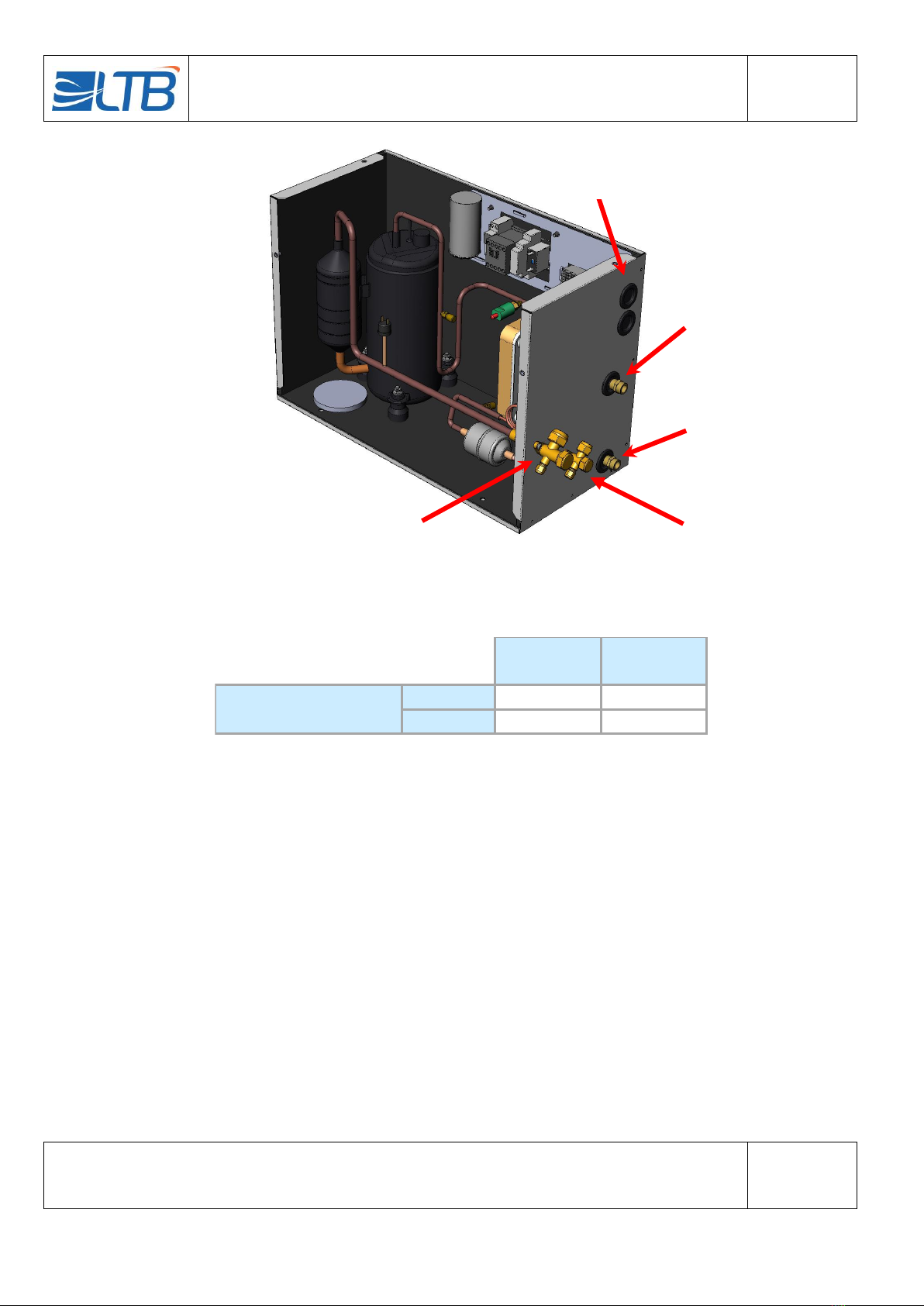
7INSTALLATION : FRIGORIFIC CONNECTIONS
All the usual precautions should be taken when setting up the refrigerant connections. In particular, it is
necessary to limit the number of bends, to make a 2% gradient on the suction line and to make the necessary
oil traps in order to have a good oil circulation. It must also be ensured that the connections are plugged in
order to prevent any impurity or moisture penetration during the installation
The maximum distance between the CU and the IU is 20 linear meters and the maximum height
difference is 5 m. The length of the liquid line as that of the suction line should not exceed 20 meters.
The GI36-40 / 75Pa, GI36-40 / 150Pa and CI36 indoor units do not have the same connection diameter as the
FW36Q6 condensing unit for the suction line. You need to install an adaptation at the CU side. This is
delivered in a separate cardboard box.
The realization of flares for the link on the flare connections should be neat. The presence of burr, crack, a too
small or too large flaring surface may cause leakage.
Flared valves must be kept closed during connection.
The tightening torque for the flared valves are:
Diameter ['']
1/4
3/8
1/2
5/8
Couple [N/m]
14 to 18
33 to 42
50 to 62
63 to 77
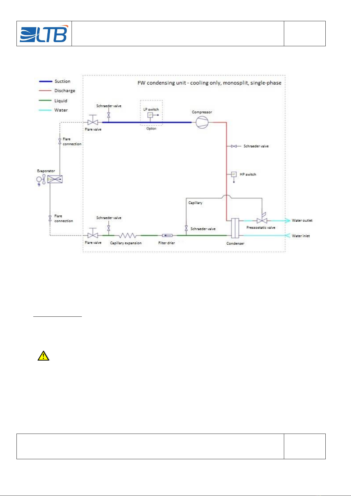
8INSTALLATION : HYDRAULIC CONNECTION
The units are delivered with 2 flexible hoses + washers to be easily connected to the water network.
In order to limit clogging of the plate heat exchanger and optimize CU operation, it is advisable to install a
strainer filter (Ø 0.1mm) on the CU water inlet piping. This filter must remain easily accessible for the operator
so that he can perform a periodical check. A strainer filter performing this function is available as an accessory.
It is delivered separately and to be connected at a workmanlike manner.
All precautions should be taken. In particular, it must be ensured that:
All piping is frost-free
There is no high point where an air pocket could be formed.
The pipes have a sufficient section for the water flow that is to be established.
The available water flow and water pressure are sufficient.
The proper functioning of the CU depends on the good quality of the heat exchange between the refrigerant
and the water to reject calories. The water inlet temperature and the flow rate are essential parameters for the
proper functioning of the installation:
If the water temperature is too high or the flow rate is too low, the power output can be lower than the
rated power.
If the water temperature is too high or the flow rate too low, the CU will get into safety (HP cut).

INSTALLATION, OPERATION AND MAINTENANCE MANUAL
FW cooling only range –Monosplit single-phase
V6
Caution: the use of a manual that is not up to date with the condensing unit version does not
engage the responsibility of LTB
Page 8 / 17
CUs are designed to operate when fed with tap water with a temperature of +15°C and a pressure of 4 bar,
with a wide tolerance around these values.
The rated water flows (eg, to provide the rated cooling capacity) of CUs are summarized in the tables below:
Rated water flow for a water inlet temperature of +15°C
Size FW
07
09
14
18
24
36
Water flow [L/h]
80
100
120
180
270
430
Rated water flow for a water inlet temperature of +30°C
Size FW
07
09
14
18
24
36
Water flow [L/h]
180
230
240
420
1000
2000
9INSTALLATION: ELECTRICAL CONNECTION OF THE CU
The installation must be carried out by a person with the appropriate skills and qualifications.
The installation must be switched off before any intervention, by cutting the power supply of the CU.
The choice of the cables must be made by the installer to comply with the standards in force at the time of
installation. Among others, the installer will have to pay attention to the electrical powers absorbed in all life
phases of the installation. The installer must also mount the necessary protections.
The CU provides power to the IU. The selection of the CU power supply cable must therefore take into account
the presence or absence of the "electrical heating" function on the IU. Suggestions regarding the supply cables
of the CU are given in the table below, but the final decision remains the responsibility of the installer.
CU power cable when IU is without electrical heating
Size FW
07
09
14
18
24
36
Section [mm²]
3 x 1.5
3 x 1.5
3 x 1.5
3 x 2.5
3 x 2.5
3 x 4.0
Max. current [A]
4.1
4.7
6.6
8.8
11.0
14.6
CU power cable when IU is a cassette with electrical heating
Size FW
07
09
14
18
24
36
Section [mm²]
-
-
3 x 1.5
3 x 2.5
3 x 2.5
3 x 4.0
Max. current [A] (cooling
mode)
-
-
6.6
8.8
11.0
14.6
Max. current [A] (heating)
-
-
6.4
6.4
9.5
9.5

INSTALLATION, OPERATION AND MAINTENANCE MANUAL
FW cooling only range –Monosplit single-phase
V6
Caution: the use of a manual that is not up to date with the condensing unit version does not
engage the responsibility of LTB
Page 9 / 17
CU power cable when IU is a ducted indoor unit with electrical heating
Size FW
07
09
14
18
24
36
Section [mm²]
3 x 2.5
3 x 2.5
3 x 2.5
3 x 2.5
3 x 4.0
3 x 6.0
Max. current [A] (cooling
mode)
4.1
4.7
6.6
8.8
11.0
14.6
Max. current [A] (heating)
9.2
9.2
10.5
10.5
19.8
29.5
The fuse chosen for the installation at the power supply board must be of the motor support type (i.g. D-curve).
CUs are supplied with a 6A fuse (see F2 in the wiring diagram in paragraph 16). It must therefore be changed
if the IU has the "electrical heating" function, the fuse to be installed is supplied with the IU (in its electrical
box). To check the value of the fuse, refer to the table below.
Control fuse protection –F2
Size FW
07
09
14
18
24
36
Indoor unit without electrical heating
6 A
6 A
6 A
6 A
6 A
6 A
Cassette indoor unit with electrical heating
-
-
10 A
10 A
10 A
10 A
Ducted indoor unit with electrical heating
10 A
10 A
10 A
10 A
20 A
GI36-40/75Pa : 32 A
GI36-40/150Pa : 25 A
The fuse must be of the motor support type (e.g. Am).

INSTALLATION, OPERATION AND MAINTENANCE MANUAL
FW cooling only range –Monosplit single-phase
V6
Caution: the use of a manual that is not up to date with the condensing unit version does not
engage the responsibility of LTB
Page 10 / 17
Below an example of a CU’s electrical panel:
Timers T1 and T2 are present when the condensing unit is delivered with the LP switch option. These times
are factory set and this setting must be checked:
Timer T1 is the anti-short cycle timer. It must be set open ¼ turned clockwise.
The timer T2 is the one that allows the shunt of the LP at startup. It must be set first cursor on 20M
and second cursor on 5. (Red light fixed in action then flashing when deactivated).
The CU and the IU must be connected according to the wiring diagram (see paragraph 16) and the
interconnection diagram supplied with the indoor unit.
Terminal block
T1 timer (with
optional LP)
T2 timer (with
optional LP)
Compressor
contactor K1
Control circuit
protection F2
Compresseur
capacitor C1
The installer checks the correct positioning of the switches of his indoor unit. (Refer to the IU
documentation).
Auto HP relay

INSTALLATION, OPERATION AND MAINTENANCE MANUAL
FW cooling only range –Monosplit single-phase
V6
Caution: the use of a manual that is not up to date with the condensing unit version does not
engage the responsibility of LTB
Page 11 / 17
10 INSTALLATION : FILLING OF REFRIGERATING GAS
The intervention must be carried out by a person with the appropriate skills and qualifications.
In particular, it must have the certificate of suitability for the handling of refrigerants. In addition,
the company employing this person must have a certificate of ability.
Once the connections have been made, airtightness must be checked keeping the flared valves closed:
Pressurizing dehydrated nitrogen and pressure maintenance control. Check sensitive areas with a
leak detector.
Vacuum drawing: obtain a pressure of 10-4 bar and maintain it for 1 hour. Then check the vacuum
resistance.
Once the airtightness is checked, the flare valves must be opened. CUs are delivered loaded for a distance of
4 meters of piping. If the lengths are higher, the load must be completed, compressor running, using a load
balance, while controlling the overheating and respecting the operating ranges in chapter 14.
Size FW
07
09
14
18
24
36
Basic load
450 g
500 g
600 g
800 g
900 g
1 000 g
Additional load
30 g / meter
50 g / meter
The final load of the installation must be reported by the installer on the condensing unit.

INSTALLATION, OPERATION AND MAINTENANCE MANUAL
FW cooling only range –Monosplit single-phase
V6
Caution: the use of a manual that is not up to date with the condensing unit version does not
engage the responsibility of LTB
Page 12 / 17
11 USE : UNIT START-UP
This paragraph applies to both the first start-up and the post-intervention startups.
The intervention must be carried out by a person with the appropriate skills and qualifications.
In particular, it must have the certificate of suitability for the handling of refrigerants. In addition,
the company employing this person must have a certificate of ability.
Before starting up the unit, you must:
Check the electrical connections are well tightened.
Check the CU is well evened.
Check the IU is well evened and that the condensate drain is well connected.
Check that the power supply voltage at terminals L and N of the CU is correct.
Check that the flare valves are open.
Check that the CU is well supplied with water.
The start of the installation is done via the IU. When the IU is in cooling demand, it sends the starting
instructions to the CU’s compressor. The compressor will start and will circulate the fluid.
There is a waiting time of up to 3 minutes for CUs without the LP pressure switch option and up to 9 minutes
for CUs with the LP pressure switch option between a cooling demand made via the remote control and the
compressor start.
The CU is equipped with the following security features:
HP pressure switch: it stops the compressor when the pressure is higher than 28 bar. Its reset is
automatic (turn off the UI and turn it back on).
BP pressure switch (option): it stops the compressor when the pressure is less than 0.5 bar. When the
pressure rises above 1.5 bar, the pressure switch closes automatically and the compressor starts
again after a 5 minute short cycle time delay (T1). It should be noted that the T2 delay allows this
safety to be shunted during the first 5 minutes of compressor start-up.
It is important to carry out complete operational tests during commissioning and to
record the measurements on the commissioning sheet (provided with this
documentation). The same tests must also be carried out during the maintenance phases
and any troubleshooting interventions.
A complete test must include at least the following measures:
Temperature measurement of HP, LP, compressor discharge, liquid, compressor suction.
Temperature measurement of the water in- and outlet.
Measurement of the current absorbed by the compressor and the IU.
The commissioning form must be completed and returned. The receipt by LTB of this
correctly completed form determines the warranty validation.

INSTALLATION, OPERATION AND MAINTENANCE MANUAL
FW cooling only range –Monosplit single-phase
V6
Caution: the use of a manual that is not up to date with the condensing unit version does not
engage the responsibility of LTB
Page 13 / 17
12 USE : FREQUENT PROBLEMS
Below is a table listing the common defaults:
Default
Probable causes
Action to be taken
The installation does not turn on
No power supply
Check voltage
Check position of the disconnecting switch
Bad wiring
Check wiring
The IU is on but does not start
Installation in security mode
Check error codes of the IU
Check the securities of the CU
Bad wiring
Check wiring
The IU is in cooling demand but the
compressor does not start.
Bad wiring
Check wiring
Installation in security mode
Check the securities of the CU
The anti-short-cycle delay has not
expired yet
Wait 3 to 8 minutes, see paragraph 10
The installation starts but pressures
are abnormal
Unadapted refrigerant load
Remove or add fluid
Gas leakage
Check airtightness
Water flow too low
Check water flow (measure, DT water)
Unadapted water temperature
Check water temperature
Non-tight compressor valves
Change compressor
Dirty filter
Check condition of the filter
The warranty does not cover the damage caused in case of incorrect implementation or -use.
13 USE: ADJUSTMENT OF THE PRESSOSTATIC WATER VALVE
The pressostatic water valve is set at the factory. Its setting should normally not be changed. However, it may
be necessary to adjust the pressostatic valve, for example:
When changing the pressostatic valve for a new valve,
In case the pressostatic valve has been disrupted
If the CU is installed in a room where the temperature is relatively high.
Pressostatic valves are built to regulate the flow of the water condenser by detecting
directly the pressure variations in the HP refrigerating circuit. They open up when the
pressure rises (direct action) according to the selected value and close when a
pressure lower than 0,5 bar occurs, in a proportional way.
The pressure for which the valve starts to open (opening point) can be adjusted using
the screw or square slot situated on top of the spring cage. The adjustment can be
done using a screwdriver or a pawl key for adjusting the valves. By turning the screw
clockwise, the opening pressure is released and vice versa.

INSTALLATION, OPERATION AND MAINTENANCE MANUAL
FW cooling only range –Monosplit single-phase
V6
Caution: the use of a manual that is not up to date with the condensing unit version does not
engage the responsibility of LTB
Page 14 / 17
The correct setting of the pressostatic valve is the one that leads to the following condensing temperatures:
FW 07 Q6
FW 09 Q6
FW 14 Q6
FW 18 Q6
FW 24 Q6
FW 36 Q6
Condensing temperature
+50°C
+50°C
+50°C
+50°C
+45°C
+45°C
These values allow to obtain the rated performance of the CU
In case the CU is located in a room where the temperature is high, it is possible that the ambient temperature
around the CU is high enough so that the pressure of the refrigerant, compressor stopped, maintains the valve
partially open. Under these conditions, the valve set point should be increased to allow the closing of the valve
during periods of compressor shut-down.
A poorly adjusted pressostatic water valve may cause excessive water consumption.
14 USE : OPERATING LIMITS
To preserve the integrity of the CU, make sure that the water inlet temperature of the unit is always between
the values given in the following table:
Minimum water inlet temperature
+5°C
Maximum water inlet temperature
+43°C
To preserve the integrity of the CU, make sure that the outdoor ambient temperature of the unit is always
between the values given in the following table:
Minimum ambient temperature
+5°C
Maximum ambient temperature
+45°C
To preserve the integrity of the CU, make sure that the LP temperature of the unit is always between the
values given in the following table:
Minimum LP temperature
-10°C
Maximum LP temperature
+10°C
To preserve the integrity of the CU, make sure that the HP temperature of the unit is always between the
values given in the following table:
Minimum HP temperature
+35°C
Maximum HP temperature
+60°C

INSTALLATION, OPERATION AND MAINTENANCE MANUAL
FW cooling only range –Monosplit single-phase
V6
Caution: the use of a manual that is not up to date with the condensing unit version does not
engage the responsibility of LTB
Page 15 / 17
15 MAINTENANCE
The maintenance must be carried out by a person with the appropriate skills and
qualifications.
The maintenance frequencies are to be adapted according to the environment and the context of the use of
the split sytem, with at least one maintenance every year.
During the maintenance, it is necessary to:
Check the filter condition of the IU and CU, clean and change them if needed.
Check the functioning of the split-system by taking measurements (see commissioning form).
Check that the HP pressure switch cuts and resets. It is possible to cause an HP shutdown by closing
the CU water supply.
Check that the LP pressure switch (option) cuts and resets. It is possible to cause a LP shutdown by
closing CU liquid flare valve.
Check for refrigerant leaks.
Check for no premature wear of the various components.
Check that the electrical connections are well tightened.
Check that there is no overheating of electrical cables.
Check out correct evacuation from the IU to the condensate tray and clean if necessary.
Check that the pressostatic water valve is not scaled and check that it operates correctly. In particular,
it must be checked that it cuts the water flow when the compressor is stopped.
All interventions on the refrigerant circuit must comply with the rules of practice and regulations in force. In
particular, it is necessary to recover the refrigerant before opening the circuit and fill the circuit with dehydrated
nitrogen before any solder.

INSTALLATION, OPERATION AND MAINTENANCE MANUAL
FW cooling only range –Monosplit single-phase
V6
Caution: the use of a manual that is not up to date with the condensing unit version does not
engage the responsibility of LTB
Page 16 / 17
16 ELECTRICAL DRAWING
OPTIONS:
Options are mentioned in dotted lines
A –Main switch
B –Automatic LP switch
CAPTION:
Wire numbers are underlined
C1 –Capacitor Compressor motor
F1 –Main circuit protection (Installer)
F2 –Control circuit protection
F6 –HP pressure switch (manual reset)
F7 –LP pressure switch (automatic reset) (Option B)
K1 –Compressor contactor
M1 –Compressor motor
Q1 –Disconnecting switch (Option A)
T1 –Anti short cycle relay (Option B)
T2 –LP shunt relay at compressor start (Option B)
TERMINAL BLOCK CONDENSING UNIT:
G –Earth
L/L1 - Phase
N –Neutral
1 –Compressor
6/7 –LP pressure switch (Option B)
NOTA:
The installer must place the electrical protections according to the
installation instructions and standards in force.
- - - - - - Wiring to be done by the installer

INSTALLATION, OPERATION AND MAINTENANCE MANUAL
FW cooling only range –Monosplit single-phase
V6
Caution: the use of a manual that is not up to date with the condensing unit version does not
engage the responsibility of LTB
Page 17 / 17
17 INSTALLATION: CHECK THE CONFIGURATION OF THE IU
The installation must be carried out by a person with the appropriate skills and qualifications.
When installing the indoor units, the installer must check the proper configuration of the switches on the printed circuit
board specific to each type of cassette* or ducted indoor unit. Wall mounted indoor units and consoles are not affected.
* Electro-mechanically modified cassettes are not affected.
The installer will have to take into account that it is the IU that authorizes the start or stop of the CU and that manages the
protocols of the different modes.
The positioning of the switches is done during the interconnection of the IUs to the CU. The installer should refer to the
interconnection diagram supplied with the indoor units.
This manual suits for next models
5
Table of contents
Popular Heat Pump manuals by other brands

evoheat
evoheat Polaris MT 70 Installation instructions manual

Dimplex
Dimplex A Class Air Source Heat Pump user guide

Viessmann
Viessmann Vitocal 200-S Installation and service instructions

A.O. Smith
A.O. Smith AHPM-270 User's information manual

Nibe
Nibe F2300 user manual

Ecotec
Ecotec EAS SERIES Installation & user manual

Atlantic
Atlantic Alfea Hybrid Duo Series Installation and commissioning instructions

Hayward
Hayward HeatPro HP50TA troubleshooting guide

Bard
Bard WPV48D installation instructions

LG
LG MULTI V ARNU-GVE Series owner's manual

HKS lazar
HKS lazar HTi20 Installation & operation manual

Panasonic
Panasonic WH-UD12HE5 Series quick guide