manuals.online logo
Brands
  1. Home
  2. •
  3. Brands
  4. •
  5. LU-VE
  6. •
  7. Fan
  8. •
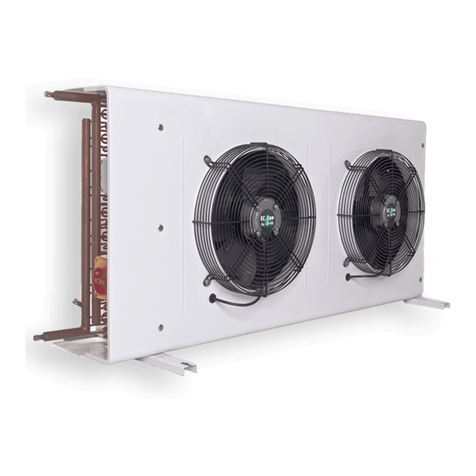
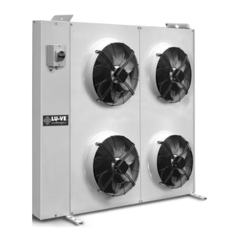
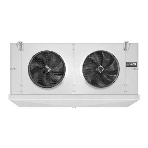
  9. LU-VE EHV Technical specifications

LU-VE EHV Technical specifications

Istruzione per il montaggio e la manutenzione per
“CONDENSATORI CON VENTILATORI ASSIALI e RAFFREDDATORI DI LIQUIDO”.
Installation and maintenance instruction for
“AXIAL FAN TYPE AIR COOLED CONDENSERS and DRY COOLERS”.
Instruction pour le montage et l’entretien pour
“CONDENSEURS AVEC VENTILATEURS HELÏCOIDES et AERO-REFRIGERANTS”.
Montage und Wartungsanleitung für
“LUFTGEKÜHLTE VERFLÜSSIGER MIT AXIALVENTILATOREN und FLÜSSIGKEITS-RÜCKKÜHLERN”.
Instrucciones de mantenimiento y montaje para
“CONDENSADORES CON VENTILADORES AXIALES y ENFRIADORES DE LIQUIDO”.
Инструкции по монтажу и техническому обслуживанию
«КОНДЕНСАТОРЫ С ОСЕВЫМИ ВЕНТИЛЯТОРАМИ и
ОХЛАДИТЕЛИ ЖИДКОСТИ»
ITALIANO
ENGLISH
FRANCAIS
DEUTSCH
ESPAÑOL
PYCCKИЙ
EHV - EAV VERSION GAS COOLER
INSTALLAZIONE ORIZZONTALE
HORIZONTAL INSTALLATION
INSTALLATION HORIZONTAL
AUFSTELLUNG HORIZONTAL
MONTAJE HORIZONTAL
МОНТАЖ Горизонтально
EHV - EAV
EHL - EAL
ATEX VERSION
INSTALLAZIONE VERTICALE
VERTICAL INSTALLATION
INSTALLATION VERTICALE
AUFSTELLUNG VERTIKAL
INSTALACIÓN VERTICAL
ПОДЪЕМ ВЕРТИКАЛЬНЫЙ
La lingua ufficiale del documento è l’inglese, le altre si intendono come traduzioni
The official language of the document is English, other means such as translation
La langue officielle du document est l'anglais, d'autres moyens tels que la traduction
Die offizielle Sprache des Dokuments ist Englisch, alle anderen gelten als Übersetzung
El idioma oficial del documento es Inglés, otros medios como la traducción
Официальный язык документа является английский, другие средства, такие как перевод
2
ITALIANO ENGLISH
FRANCAIS DEUTSCH
ESPAÑOL PYCCKИЙ
3
• Prima di sollevare gli apparecchi controllare l’integrità strutturale degli organi di sollevamento e il loro corretto fissaggio alla struttura.
• Before lifting the units, please check the structural integrity of the lifting devices and their proper fixing to the structure.
• Avant de soulever les appareils, contrôler que les dispositifs de levage sont en bon état et qu'ils sont fixés correctement à la structure.
• Vor dem Anheben der Geräte die strukturelle Vollständigkeit der Hebevorrichtungen und ihre korrekte Befestigung an der Struktur kontrollie-
ren
• Antes de proceder en la elevación del aparato, se debe controlar la integridad estructural de la elevación y su posterior fijación correcta en la
estructura.
• До поднятия оборудования проверить целостность креплений и их надежное крепления к корпусу
SOLLEVAMENTO / LIFTING SKETCH / SOULEVEMENT / ANHEBEN / LEVANTARLO / ПОДЪЕМ
EHV...H - EAV...H
EHL...H - EAL...H
VERTICALE / VERTICAL / VERTICALE / VERTIKAL / VERTICAL / ВЕРТИКАЛЬНЫЙ
ORIZZONTALE / HORIZONTAL / HORIZONTAL / HORIZONTAL / HORIZONTAL / ГОРИЗОНТАЛЬНЫЙ
EHV...H - EAV...H
EHL...H - EAL...H
Solo per:
Only for:
Seulement
pour:
Nur Für:
Solo para:
Только для:
Solo per:
Only for:
Seulement pour:
Nur Für:
Solo para:
Только для:
4
SOLLEVAMENTO / LIFTING SKETCH / SOULEVEMENT / ANHEBEN / LEVANTARLO /ПОДЪЕМ
VERTICALE / VERTICAL / VERTICALE
VERTIKAL / VERTICAL / ВЕРТИКАЛЬНЫЙ
EHV...V - EAV...V
EHL...V - EAL...V EHV...H - EAV...H
EHL...H - EAL...H
ORIZZONTALE / HORIZONTAL / HORIZONTAL
HORIZONTAL / HORIZONTAL / ГОРИЗОНТАЛЬНЫЙ
ATTENZIONE
CAUTION
ATTENTION
ACHTUNG
ATENCIÓN
ВНИМАНИЕ
30°max
30°max
5
INSTALLAZIONE VERTICALE / VERTICAL INSTALLATION / INSTALLATION VERTICALE / AUFSTELLUNG VERTIKAL /
INSTALACIÓN VERTICAL / ПОДЪЕМ ВЕРТИКАЛЬНЫЙ
Posizione dei piedi / Feet position / Position des pieds
Aufstellungposition / Posición de los pies / Положение опор
• Attacchi lati opposti
• Connection opposite sides
• Connexions côté opposés
• Anschlüsse Zweiseitig
• Conexión latos opposto
• крепления боковые
GUIDA DISTANZE
DISTANCES GUIDE
GUIDE DISTANCES
ENTERNUNGEN ANLEITUNG
DISTANCIA DE ONSTÁCULOS
РАССТОЯНИЯ
EHV...V - EAV...V
EHL...V - EAL...V
OPTIONAL
EHV...V - EAV...V 2
11
1
1
EHV...V - EAV...V
CONTROVENTATURA
WINDBRACING
CONTEVENTEMENT
WINDVERSTREBUNG
TENSORES CONTROVIENTO
КОНТРГАЙКА
6
INSTALLAZIONE VERTICALE / VERTICAL INSTALLATION / INSTALLATION VERTICALE / AUFSTELLUNG VERTIKAL /
INSTALACIÓN VERTICAL / ПОДЪЕМ ВЕРТИКАЛЬНЫЙ
EHL...V - EAL...V Posizione dei piedi / Feet position / Position des pieds
Aufstellungposition / Posición de los pies / Положение опор
• Attacchi lati opposti
• Connection opposite sides
• Connexions côté opposés
• Anschlüsse Zweiseitig
• Conexión latos opposto
• крепления боковые
POSIZIONE ATTACCHI Circuiti: (A, F, N) = lati opposti (B, C, D, E) = stesso lato
CONNECTIONS POSITION Circuits (A, F, N) = opposite side (B, C, D, E) = same side
POSITION CONNEXION Circuits (A, F, N) = côté opposés (B, C, D, E) = même côté
STELLUNG DER ANSCHLÜSSE Kreisläufe: (A, F, N) = zweiseitig (B, C, D, E) = Einseitig
POSICIÓN CONEXIÓN Circuitos: (A, F, N) = latos opposto (B, C, D, E) = mismo lato
Положение крепления Контуры (A, F, N) = Противоположная сторона (B, C, D, E) = та же сторона
EHL...V - EAL...V
TIPO DI CIRCUITO / TYPE CIRCUIT / CIRCUIT TYPE / ROHRSCHALTUNG / CIRCUITOS / ТИП КОНТУРА
Solo 2 attacchi per:
Only 2connections for:
Seulement 2 raccords pour:
Nur 2 Anschlüsse für:
Solo 2 conexión para:
Только 2 крепления для:
N(•)
Modelli / Type / Modèle
Modell Modelo / Модель
476N - 526N - 530N
560N - 590N
GUIDA DISTANZE
DISTANCES GUIDE
GUIDE DISTANCES
ENTERNUNGEN ANLEITUNG
DISTANCIA DE ONSTÁCULOS
Расстояния
EHL...V
EAL...V
EHL...V
EAL...V
CONTROVENTATURA
WINDBRACING
CONTEVENTEMENT
WINDVERSTREBUNG
TENSORES CONTROVIENTO
КОНТРГАЙКА
7
INSTALLAZIONE VERTICALE per H/V VERTICAL INSTALLATION for H/V INSTALLATION VERTICALE pour H/V
AUFSTELLUNG VERTIKAL für H/V MONTAJE VERTICAL para H/V ВЕРТИКАЛЬНЫЙ МОНТАЖ для H/V
EHV...H per / for / pour / für / para / для ...V
EHL...H per / for / pour / für / para / для ...V EAV...H per / for / pour / für / para / для ...V
EHL...H per / for / pour / für / para / для ...V
Montaggio piedi installazione H per V
Installation feet H for V installation
Mondage des pieds installation H pour V
Montage der Füße H f¨ür V Austellung
Montaje de los pies intalación H para V
Монтаж опор H для V
Vedere pagina 8 / See page 8 / Voir page 8 / Siehe auf seite 8 / Ver pagina 8 / См. Стр. 8
8
INSTALLAZIONE ORIZZONTALE / HORIZONTAL INSTALLATION / INSTALLATION HORIZONTAL / AUFSTELLUNG HORIZONTAL
MONTAJE HORIZONTAL / МОНТАЖ Горизонтально
Sollevamento / Lifting sketch / Soulevement / Anheben / Levantarlo / Подъем
EHV...H - EAV...V
EHL...H - EAL...V
RIBALTAMENTO
Prima di sollevare gli apparecchi controllare l’integrità
strutturale degli organi di sollevamento e il loro cor-
retto fissaggio alla struttura
•Durante l’operazione di ribaltamento dell’apparec-
chio fare attenzione che:
– le funi di sollevamento siano sempre in tiro vertical-
mente (3-5)
– la base dell’apparecchio sia bloccata con appositi
dispositivi (4) onde evitare lo scivolamento.
•l’operatore deve operare ai fianchi dell’apparecchio
e non sostare nelle zone operative di ribaltamento (7)
TURNOVER
Before lifting the units, please check the structural
integrity of the lifting devices and their proper fixing to
the structure
•When turning over the equipment watch for:
– ropes tension shall be worked vertically (3-5)
– the equipment basement shall be locked with suita-
ble devices (4).
•When turning over the equipment the operator shall
be located in (7).
Nobody shall walk or stop under a suspended load.
RENVERSEMENT
Avant de soulever les appareils, contrôler que les
dispositifs de levage sont en bon état et qu'ils sont
fixés correctement à la structure
•Durant l’opération de basculage de la pièce:
– maintenir toujours la raideur des câbles en sens
vertical (3-5)
– bloquer la base de l’appareil au moyen de disposi-
tifs convenables (4).
•Durant l’opération de basculage, l’opérateur doit se
placer à côté:
personne ne dovra demeurer dans l’aire de travail (7)
UMKIPPEN
Vor dem Anheben der Geräte die strukturelle
Vollständigkeit der Hebevorrichtungen und ihre kor-
rekte Befestigung an der Struktur kontrollieren
•Während des Umkippens des Teils stets
– die Spannung der Seile in Senkrechtrichtung (3-5)
beibehalten
– die Grundplatte des Gerätes mit entsprechenden
Vorrichtungen festellen(4).
•Bei Umkippen des Teils muss sich der Bediener auf
der Seite (7) befinden; niemand darf sich im Ar-
beitsbereich aufhalten.
TUMBADO
Antes de proceder en la elevación del aparato, se
debe controlar la integridad estructural de la eleva-
ción y su posterior fijación Correcta en la estructura
•Durante la operación de tumbar el equipo:
- que los cables para levantarlo tiren de forma verti-
cal (3-5)
- que la base del aparato se bloquee debidamente
con los tacos (4) para
evitar su deslizamiento.
•El encargado de manipular deberá evitar colocarse
en las zonas de posible volcado del equipo, trabajan-
do desde los lados (7)
ПЕРЕВОРОТ
До поднятия оборудования проверить
целостность креплений и их надежное крепления
к корпусу
Во время операции переворота изделия следует
соблюдать:
- подъемные тросы всегда вертикально
расположены инатянуты (3-5)
- основание изделия заблокировано винтами (4)
чтобы избежать проскальзывание
• рабочий должен располагаться сбоку от изделия
вне зоны подъемных работ (7)
9
INSTALLAZIONE ORIZZONTALE / HORIZONTAL INSTALLATION / INSTALLATION HORIZONTAL / AUFSTELLUNG HORIZONTAL
MONTAJE HORIZONTAL / МОНТАЖ Горизонтально
INSTALLAZIONE ORIZZONTALE / HORIZONTAL INSTALLATION / INSTALLATION HORIZONTAL / AUFSTELLUNG HORIZONTAL
MONTAJE HORIZONTAL / МОНТАЖ Горизонтально
EHV...H
EAV...H Posizione dei piedi / Feet position / Position des pieds
Aufstellungposition / Posición de los pies / Положение опор
EHL...H
EAL...H Posizione dei piedi / Feet position / Position des pieds
Aufstellungposition / Posición de los pies / Положение опор
EHL...H
EAL...H
POSIZIONE ATTACCHI Circuiti: (A, F, N) = lati opposti (B, C, D, E) = stesso lato
CONNECTIONS POSITION Circuits (A, F, N) = opposite side (B, C, D, E) = same side
POSITION CONNEXION Circuits (A, F, N) = côté opposés (B, C, D, E) = même côté
STELLUNG DER ANSCHLÜSSE Kreisläufe: (A, F, N) = zweiseitig (B, C, D, E) = Einseitig
POSICIÓN CONEXIÓN Circuitos: (A, F, N) = latos opposto (B, C, D, E) = mismo lato
Положение крепления Контуры (A, F, N) = Противоположная сторона (B, C, D, E) = та же сторона
TIPO DI CIRCUITO / TYPE CIRCUIT / CIRCUIT TYPE / ROHRSCHALTUNG / CIRCUITOS / ТИП КОНТУРА
Solo 2 attacchi per:
Only 2connections for:
Seulement 2 raccords pour:
Nur 2 Anschlüsse für:
Solo 2 conexión para:
Только 2 крепления для:
N(•)
Modelli / Type / Modèle
Modell Modelo / Модель
476N - 526N - 530N
560N - 590N
10
GUIDA DISTANZE / DISTANCES GUIDE / GUIDE DISTANCES / ENTERNUNGEN ANLEITUNG / DISTANCIA DE OBSTÁCULOS / ИНСТРУКЦИИ
РАССТОЯНИЯ
ATTACCHI / CONNECTIONS / RACCORDS / ANSCHLÜSSE / CONEXIÓN / КРИПЛЕНИЙ
• Prima di procedere ai collegamenti dei collettori/distributori, è
obbligatorio assicurarsi che il circuito d’alimentazione sia
chiuso (assenza di pressione).
Durante l’operazione di saldatura, assicurarsi di indirizzare la fiam-
ma in modo da non investire la macchina (eventualmente interpor-
re una protezione).
• Before to proceed with the collectors/distributors connections
it is mandatory to comply as follows make sure the supply
circuit is closed (no pressure).
When performing welding operations, make sure the flame nozzle
is not aimed toward the equipment (insert a shield of required).
• Avant de procéder aux raccordements des collesteurs/
distributeurs, est obligatoire de s’assurer que le circuit d’ali-
mentation est fermé (absence de pression).
Durant la soudure, de veiller à diriger la flamme de façon à ne pas
toucher la machine (éventuellement, il conviendra de placer une
protection devant la machine).
• Vor Anschluss der Sammelrohre/Verteilerrohre müssen fol-
gende Vorschriften eingehalten werden Sicherstellen, daß der
Speisungskreis geschlossen ist (kein Druck).
Beim Schweißen die Flamme so ausrichten, daß die Maschine
nicht getroffen wird (eventuell mit einem Schutz versehen).
• Antes de proceder al conexionado de los colectores/
distribudores, es obligatorio segurarse que el circuito de ali-
mentación esté cerrado (falta de presión).
Durante la operación de soldadura, asegurarse de que la llama se
coloque fuera de la dirección de la máquina (opcionalmente colo-
car una protectión).
• Перед подсоединением коллектора/распределителя,
необходимо Удостовериться в том, что контур закрыт
(давление в системе отсутствует).
Bо время проведения пайки, следует направлять пламя таким
образом, чтобы избежать повреждений изделия (использовать
средства индивидуальной защиты).
• Non adattare la posizione dei collettori alla linea.
• Do not adapt headers position to the suction line
• Ne pas adapter la position du collecteurs à la ligne.
• Sammlerposition nicht an Leitung anpassen !
• No adaptar la posición de los colectores a la lìnea de succión
• Не использовать положение коллекторов в одну линию.
NO - NO - NON
NEIN - NO - НЕТ SI - YES - OUI
JA - SI - ДА
*Ø Mod. Type
1 1/2” DIN 40
2” DIN 50
2 1/2” DIN 65
4” DIN 100
EHL - EAL
(SPECIAL)
Solo per:
Onlyfor:
Seulement pour:
Nur für:
Solo para:
Только для:
I Ø sono indicati sui nostri cataloghi.
The Øare detailed in our catalogues.
Les Ø sont indiqués dans nos catalogues.
Die Ø sind in unseren Katalogen angegeben
LosØ indicados en los catálogos.
Диаметры указаны в каталогах
EHV...H - EAV...H
EHL...H - EAL...H
11
INFORMAZIONI GENERALI / GENERAL INFORMATION
I prodotti LU-VE della gamma ATEX sono adatti al funzionamento in
atmosfere potenzialmente esplosive conformemente alla direttiva
2014/34/UE, gruppo II categoria 2 e 3. I prodotti sono verniciati con
una vernice adatta a condurre corrente, in modo da avere una strut-
tura della macchina equipotenziale. L’installatore deve ga-
rantire la corretta messa a terra delle macchine. È
responsabilità dell’acquirente e/o dell’utente di far eseguire l’istalla-
zione e la manutenzione a personale qualificato, mettendo in atto
tutte le procedure di sicurezza necessarie e este dalle leggi,
regole e norme in vigore nel paese in cui l’apparecchiatura è messa
in funzione. Le indicazioni necessarie al corretto
utilizzo delle macchine oggetto di questo manuale, si completano
con quanto riportato nel manuale di uso e manutenzione del motore,
che viene fornito assieme alla macchina. Le macchine sono idonee
per l’uso in zone classificate con presenza di gas / vapori (zona 1) e
polveri combustibili (zona 21), progettate e costruite in accordo alla
direttiva ATEX 2014/34/UE, gruppo II, categoria 2 GD. Tutte le parti
elettriche dei ventilatori assiali sono conformi alla direttiva ATEX
2014/34/UE e idonee al gruppo II, alle zone 1 e 21 (categoria 2 GD),
alle sostanze presenti, alla temperatura superficiale e alla tempera-
tura ambiente. Le macchine e i ventilatori ivi installati devono esse-
re installati e mantenuti in accordo con le norme impiantistiche e di
manutenzione per ambienti classificati a rischio di esplosione per
presenza di gas / vapori e polveri combustibili (esempio: EN
60079-14, EN 60079-17, EN 61241-14, EN 61241-17 oppure altre
norme/standard nazionali).
Ogni ventilatore deve essere provvisto di un interruttore d’emergenza
che permetta di interrompere il collegamento con la rete elettrica di
alimentazione.
The ATEX range of LU-VE products are suitable for operation in
potentially explosive atmospheres conforming to Directive 2014/34/
UE, group II categories 2 and 3. The products are treated with a
current-conducting paint, giving an equipotential structure to the ma-
chine. The installer has to guarantee the correct grounding of the
machine. It is the responsibility of the purchaser and/or the user to
have the installation and maintenance done by qualified personnel,
implementing all the necessary safety procedures required by law,
regulations and standards in force in the country where the machine
is put into service. The instructions necessary for the correct use of
the machines covered in this manual are completed with the contents
of the motor use and maintenance manual which is supplied with the
machine.
The machines are suitable for use in zones classified with the pre-
sence of gas/vapours (zone 1) and combustible dust (zone 21), desi-
gned and manufactured in accordance with ATEX Directive 2014/34/
UE, group II, category 2 GD. All electrical parts of the axial fans com-
ply with ATEX Directive 2014/34/UE and are suitable for group ll,
zones 1 and 21 (category 2GD), for substances present, for the sur-
face temperatures and the ambient temperatures. The machines and
the fans installed in them must be installed and maintained in accor-
dance with the standards of the plant and of maintenance for envi-
ronments classified as at risk of explosion due to the presence of
gas/vapours and combustible dusts (for example: EN 60079-14, EN
60079-17, EN 61241-14, EN 61241-17 or other national standards).
Each fan must be fitted with an emergency switch which can interrupt
the connection to the electrical mains power supply.
RICEVIMENTO ED ISPEZIONE / RECEIPT AND INSPECTION OF GOODS
Tutti i prodotti LU-VE sono controllati accuratamente prima della
spedizione per assicurare i più elevati standard di qualità.
È responsabilità del destinatario controllare che le machine e i venti-
latori ricevuti siano conformi a quanto ordinato e non abbiano subito
danni durante il trasporto. In particolare va controllato che la classifi-
cazione ATEX delle macchine ricevuto corrisponda all’utilizzo che ne
dovrà essere fatto.
In particolare si raccomanda di eseguire i seguenti controlli:
• Confrontare che le unità corrispondono per codice, descrizione e
tipologia con quanto ordinato.
• Controllare che non vi siano parti danneggiate o mancanti.
• Controllare che non vi siano parti mobili se non quelle progettate
per esserlo.
• Verificare che la girante ruoti liberamente senza toccare altre parti
del ventilatore, che non presenti segni evidenti di deformazioni locali
e sia ben fissata sull’albero del motore.
• Controllare che le viti di fissaggio siano correttamente serrate.
All LU-VE products are carefully checked before being dispatched to
ensure the highest standards of quality.
It is the responsibility of the consignee to check that the machines
and fans received correspond exactly to the goods ordered and that
they have not been damaged during transport. In particular, it must
be checked that the ATEX classification of the machines received
matches the use to which they will be put.
It is especially recommended that the following inspections are car-
ried out:
• Check that the units correspond by code, description and type to
those ordered;
• Check that there are no damaged or missing parts;
• Check that there are no mobile parts apart from those designed to
be so;
• Verify that the rotor turns freely without touching other parts of the
fan, that there are no evident signs of local deformation and that it is
firmly attached to the shaft of the motor;
• Check that the fastening screws are correctly tightened.
CONDIZIONI DI FUNZIONAMENTO / OPERATING CONDITIONS
Le condizioni standard di funzionamento per i ventilatori sono:
• Ciclo continuo S1, commutazioni troppo frequenti non sono previste
• Temperatura ambiente: - 20° C, + 60° C
• Pressione atmosferica compresa tra gli 0,8 bar e 1,1 bar
• Massimo volume di ossigeno del 21%
• Aria pulita
Per temperature ambiente diverse da quella standard e per cicli di-
scontinui si dovranno utilizzare ventilatori specifici, tali condizioni
dovranno essere indicate in fase d’ordine e saranno riportate in eti-
chetta. I ventilatori sono adatti al funzionamento nelle condizioni del
gruppo e della categoria riportati sull’etichetta.
Standard operating conditions for the fans are:
• S1 continuous duty, there is no frequent switching
• Ambient temperature: - 20° C, + 60° C
• Atmospheric pressure between 0.8 bar and 1.1 bar
• Maximum oxygen volume 21%
• Clean air
For temperatures other than standard and for intermittent duties,
specific fans must be used; such conditions must be indicated at the
order stage and will be reported on labels. The fans are suitable for
operation in the conditions of the group and category reported on the
label.
RESISTENZA ALLA CORROSIONE / CORROSION RESISTANCE
I ventilatori non sono costruiti per resistere ad agenti corrosivi, salvo
specifiche richieste all’ordine.
The fans are not constructed to resist corrosive agents, unless speci-
fied at the order stage.
EQUILIBRATURA / BALANCING
Le giranti sono equilibrate in conformità alla ISO 1940/1-1986 grado
G6.3. I ventilatori dovranno funzionare con le giranti equilibrate, vi-
brazioni anomale sono indice dello stato di non equilibratura del ven-
tilatore.
The rotors are balanced in compliance with ISO 1940/1-1986 grade
G6.3. The fans must operate with the rotors balanced; anomalous
vibration is a sign of the unbalanced state of the fan.
12
Prima di procedere ai collegamenti elettrici, è obbligatorio:
• Assicurarsi che il circuito elettrico d’alimentazione sia aperto.
Before to proceed with electrical wirings it is mandatory to com-
ply as follows:
• Make sure the power line circuit is open.
Avant de procéder aux raccordements électriques, est obligatoi-
re:
• De s’assurer que le circuit électrique d’alimentation est ouvert.
Vor Ausführung der Elektroanschlüsse müssen folgende Vor-
schriften eingehalten werden:
• Sicherstellen, daß der Stromversorgungskreis offen ist.
Ante de proceder al conexionado eléctrico es obligatorio:
• Asegurarse que el circuito de alimentación eléctrico esté abierto.
Перед тем как произвести все электро подключения следует:
•Удостовериться в том что контур незамкнут
COLLEGAMENTO DEI MOTORI / MOTORS CONNECTION / CONNEXION DES MOTEURS / MOTORSCHALTUGEN / CONEXIÓN DE MOTORES /
ПОДКЛЮЧЕНИЯ МОТОРЫ
II 2GEEx DIIB T4
CLASSIFICAZIONE ATEX / ATEX CLASSIFICATION
I ventilatori del Gruppo II categoria 2, adatti all’utilizzo in atmosfere
con presenza di polvere (2D), devono essere dotati di un
sistema di controllo delle vibrazioni che scolleghi il ventilatore dalla
linea di alimentazione elettrica nel caso si manifestino
vibrazioni potenzialmente pericolose conformemente alla ISO 14694.
Il dispositivo non deve essere neutralizzato né spostato per nessuna
ragione e deve essere periodicamente testato. Tale dispositivo può
essere fornito su richiesta.
Fans in Group II category 2, suitable for use in atmospheres with the
presence of dust (2D) must be fitted with a vibration control system
which can disconnect the electrical power supply line if there are
potentially dangerous vibrations as stated in ISO 14694. The device
must not be disarmed or moved for any reason and must be periodi-
cally tested. Such a device can be supplied on request.
Caratteristiche tecniche ventilatori
Ventilatori caratterizzati da motore in ghisa adatto a norma ATEX con
ventola antistatica. Il ventilatore ha una scatoletta elettrica per il col-
legamento elettrico. Tutti i collegamenti elettrici sono a carico dell’in-
stallatore
Grado di protezione IP 55
Tensione di alimentazione: standard 400V-3PH-50Hz. Sono possibili
a richiesta diversi tipi di alimentazione
Potenza assorbita e corrente: vedere selezione tecnica della macchi-
na e targa matricolare
Diametro dei ventilatori: da 500 a 1000mm
Esempio classificazione ATEX:
Technical characteristics of the fans
These are fans with cast iron motors suitable for ATEX norm with
antistatic rotor. The fan has an electrical junction box for connections.
All electrical connections are the responsibility of the installer.
Protection grade IP 55.
Power supply voltage: standard 400V-3PH-50Hz. Other types of
power supply are available on request.
Power draw and current: see the technical selection of the machine
and the serial number plate.
Fan diameter: from 500 to 1000 mm
ATEX classification example
13
CARATTERISTICHE / CHARACTERISTICS / CARACTERISTIQUES / MERKMALEN / CARACTERISTICAS / ТЕХ ОПИСАНИЕ
Scambiatore:
Tubi: • Cu
Alette: • Al
• Alupaint a richiesta (protezione anticorrosiva a base poliestere, per applicazio-
ni e limiti resistenza corrosione contattare LU-VE).
• Cu a richiesta
Collettori: • Cu (versione condensatore)
• Cu con attacco in Fe filettato (flangiato a richiesta) (ver sione dry cooler).
• Fe con attacco in Fe (versione gas cooler)
Le parti in ferro dei dry cooler sono fornite con una vernice che fornisce una protezione
temporanea contro la corrosione. Durante l'installazione va data una protezione definiti-
va. I collettori dei gas cooler hanno una protezione definitiva, tranne che per la zona ove
viene eseguita la saldatura durante l'installazione, li la protezione finale deve essere
realizzata dall'installatore.
Fluidi impiegabili:
EHV9 - EAV8 - EAV9(condensatori):•R407F •R449A •R134A •R407C•R404A •R507A
•R410A •R22 •R407A •R417A •R422A •R422D
•R448A •R450A •R513A •R32
EHL9 - EAV8 - EAV9 (dry cooler): • acqua • acqua glicolata
• altri fluidi mono fase non aggressivi per rame, contattare
LU-VE per dettagli.
EHV9 - EAV8 - EAV9 CO2: • CO2
Max condizioni di utilizzo:
EHV9 - EAV8 - EAV9 (condensatori): • 30 bar, T ingresso gas caldo 85 °C
EHL9 - EAV8 - EAV9 (dry cooler): • 10 bar, T ingresso liquido 60 °C (*)
EHV9 - EAV8 - EAV9 CO2: • 120 bar, T ingresso CO2 150 °C
(*) La temperatura può essere superiore per alcune ventilazione, contattare
Luve per maggiori dettagli.
Heath Exchanger:
• Cu tubes
• Al fins
• Alupaint fins on requist (polyester based corrosion protection, for
applications and limits corrosion resistance contact LU-VE).
• Cu fins on request
Copper headers: • Cu (condenser version)
• with iron connection thread (Flanged on request), (dry cooler ver-
sion).
• with iron connection, (gas cooler version)
The iron parts of the dry cooler is provided with a coating that provides temporary pro-
tection against corrosion. During the installation should be given permanent protection.
The headers of gas cooler has a final protection, except for the area where welding is
performed during installation, the final protection will be achieved by the installer.
Fluids used:
EHV9 - EAV8 - EAV9 (condenser):•R407F •R449A •R134A •R407C•R404A •R507A
•R410A •R22 •R407A •R417A •R422A •R422D
•R448A •R450A •R513A •R32
EHL9 - EAV8 - EAV9 (dry cooler): • water • brine water
• other fluid mono phase non-aggressive to copper, contact
LU-VE for details.
EHV9 - EAV8 - EAV9 CO2: • CO2
Max conditions of use:
EHV9 - EAV8 - EAV9 (condenser):
• 30 bar, T 85 °C hot gas inlet
EHL9 - EAV8 - EAV9 (dry cooler): • 10 bar, T 60 °C fluid inlet (*)
EHV9 - EAV8 - EAV9 CO2:• 120 bar, T 150 °C CO2 inlet
(*) The temperature can be higher for some ventilation, contact Luve for more details.
ITALIANO ENGLISH
Echangeur :
Tubes: • Cuivre
Ailettes: • Aluminium
• Alupaint sur demande (protection anti-corrosion, à base de polyester;
pour les applications et les limites de résistance à la corrosion, contacter
LU-VE)
• Cuivre sur demande
Collecteurs: • Cuivre (version condenseur)
• Cuivre avec raccordements en acier fileté (à brides sur demande)
(version dry cooler)
• Acier avec raccordements en acier (version gaz cooler)
Les parties en acier du dry cooler sont revêtues d’un vernis qui les protège provisoire-
ment contre la corrosion. Lors de l’installation, une protection définitive doit être appli-
quée.
Les collecteurs des gaz coolers ont une protection définitive, à l’exception de la zone où
sera réalisée la brasure lors de l’installation ; la protection définitive doit être réalisée par
l’installateur.
Fluides utilisés:
EHV9 - EAV8 - EAV9 (condenseur):•R407F •R449A •R134A •R407C•R404A •R507A
•R410A •R22 •R407A •R417A •R422A •R422D
•R448A •R450A •R513A •R32
EHL9 - EAV8 - EAV9 (dry cooler): • eau • eau glycolée
•autres fluides monophasés non agressifs pour le cuivre; contacter
LU-VE pour plus de détails.
EHV9 - EAV8 - EAV9 CO2: • CO2
Conditions maximales d’utilisation
EAV5 - SAV6 - EAV6 - SAV7 (condenseur):
• 30 bar, Température d’entrée gaz chaud = 85 °C
EHV9 - EAV8 - EAV9(dry cooler) : • 10 bar, Température d’entrée liquide = 60 °C (*)
EHV9 - EAV8 - EAV9 CO2: • 120 bar, Température d’entrée CO2 = 150 °C
(*) La température peut être supérieure pour quelques ventilations, contacter LU-VE
pour plus de détails.
Wärmetauscher:
Rohre: • Cu
Lamellen: • Al
• Alupaint auf Anfrage (Rostschutz auf Polyesterbasis, für Infos
bezgl. Anwendung und Rostschutzeinschränkungen bitte mit Lu-ve in
Verbindung setzen).
• Cu auf Anfrage
Sammelrohre: • Cu (Ausführung Verflüssiger)
• Cu mit Gewinde versehenem Fe-Anschluss (mit Flansch auf Anfra-
ge) (Ausführung Rückkühler).
• Fe mit Fe - Anschluss (Ausführung Gaskühler)
Die Eisenteile der Rückkühler sind mit einer zeitweiligen korrosionsbeständigen Lackie-
rung versehen. Bei der Montage wir der endgültige Schutz aufgetragen. Die Sammelroh-
re der Gaskühler haben eine endgültige Schutzschicht, außer dort, wo während der
Montage geschweißt wird, dort muss die endgültige Schutzschicht vom Monteur aufge-
bracht werden.
Verwendbare Kältemittel:
EHV9 - EAV8 - EAV9 (Verflüssiger):•R407F •R449A •R134A •R407C•R404A •R507A
•R410A •R22 •R407A •R417A •R422A •R422D
•R448A •R450A •R513A •R32
EHL9 - EAV8 - EAV9 (Rückkühler): • Wasser • Glykolwasser
• andere Einphasen - Fluids, die Kupfer nicht angreifen. Für Ein
zelheiten setzen Sie sich mit LU-VE in Verbindung.
EHV9 - EAV8 - EAV9 CO2: • CO2
Max Anwendungsbedingungen:
EAV5 - SAV6 - EAV6 - SAV7 (Verflüssiger):
• 30 bar, T Eingang warmes Gas 85 °C
EHV9 - EAV8 - EAV9 (Rückkühler): • 10 bar, T Eingang Flüssigkeit 60 °C (*)
EHV9 - EAV8 - EAV9 CO2: • 120 bar, T Eingang CO2 150 °C
(*) Die Temperatur darf bei einigen Ventilationen höher sein, für Einzelheiten setzen Sie
sich mit LU-VE in Verbindung.
FRANCAIS DEUTSCH
Intercambiador de calor:
Tubos: • Cu
Aletas: • Al
• Alupaint BAJO SOLICITUD (protección a base poliéster para aplicaciones
corrosivas, para conocer la resistencia máxima de anticorrosión contactar
con LU-VE
• Cu Bajo Solicitud
Colectores: • Cu (versión para condensadores)
• Cu Cabezal roscado en Fe (Bridas bajo solicitud) (versión para dry
cooler).
• Fe cabezal Fe (versión para gas cooler)
Los cabezales en hierro del Dry -coooler se proporcionan con una pintura de protección
temporal contra la corrosión.
Durante la instalación se debe aplicar la protección definitiva.
Los colectores de los gas cooler tienen una protección definitiva, con exeptión de la
zona donde a estado hecha la soldadura durante la instalación; en este lugar, es el
instalador que tiene que realizar la protección definitiva.
Liquídos utilizables:
EHV9 - EAV8 - EAV9 (condensador):•R407F •R449A •R134A •R407C•R404A •R507A
•R410A •R22 •R407A •R417A •R422A •R422D
•R448A •R450A •R513A •R32
EHL9 - EAV8 - EAV9 (dry cooler): • agua • aguaglicolada
• otros liquídos Monofase que no sean agresivos para el
cobre, contacte LU-VE para más detalles.
EHV9 - EAV8 - EAV9 CO2: • CO2
Condicciónes maxíma de empleo:
EAV5 - SAV6 - EAV6 - SAV7 (condensador):
• 30 bar, T entrada gas caliente 85 °C
EHV9 - EAV8 - EAV9(dry cooler): • 10 bar, T entrada liquído 60 °C (*)
EHV9 - EAV8 - EAV9 CO2: • 120 bar, T entrada CO2 150 °C
(*) Las temperaduras pueden ser más altas para algunas ventilaciónes, contacte Luve
para más detalles.
ESPAÑOL PYCCKИЙ
Теплообменник:
• Медные трубки
• Алюминиевые ламели
• По запросу ламели с Alupaint (антикоррозийное покрытие на основе
полиэстера, для информации о нанесении и степени устойчивости к
коррозии обращайтесь в ЛЮ-ВЭ)
Фланцы:
• Медные (конденсаторы)
• Со стальным резьбовым соединением (с резьбой по запросу), (драйкулеры)
• Со стальным соединением (газовые охладители) Железные части драй-кулеров
имеют покрытие, обеспечивающее временную защиту от коррозии.
Во время установки следует обеспечить постоянной защитой.
Фланцы газовых охладителей имеют окончательную защиту, за исключением
мест, где производится сварка во время установки,
окончательная защита осуществляется монтажниками.
Хладагенты:
EHV9 - EAV8 - EAV9 (конденсатор) •R407F •R449A •R134A •R407C•R404A •R507A
•R410A •R22 •R407A •R417A •R422A •R422D
•R448A •R450A •R513A •R32
EHL9 - EAV8 - EAV9 (драй кулер) • вода •раствор гликоля• однофазная
жидкость,неагрессивная к меди, для информации
обращайтесь в ЛЮ-ВЭ
EHV9 - EAV8 - EAV9 CO2
Предельные условия эксплуатации:
EAV5 - SAV6 - EAV6 - SAV7 (конденсатор)
• 30 bar, T 85 °C горячего газа на входе
EHV9 - EAV8 - EAV9 (драй кулер)• 10 bar, T 60 °C жидкости на входе (*)
EHV9 - EAV8 - EAV9 CO2:• 120 bar, T 150 °C CO2 на входе
(*) Температура для вентиляции может быть выше. Для информации
обращайтесь в ЛЮ-ВЭ
14
MANUTENZIONE / MAITENANCE / ENTRETIEN / VARTUNG / MANUTENCIÓN / ТЕХИЧЕСКОЕ ОБСЛУЖИВАНИЕ
• Verificare periodicamente
l’integrità dei collegamenti della messa a terra
e dell’equipotenzialità dell’apparecchiatura
• Überprüfen Sie in regelmäßigen Abständen
(mindestens 1 Mal pro Monat), um die Integri-
tät der Verbindungen der Erdung und Poten-
tial Ausrüstung
• Periodically check (at least once a month)
the integrity of grounding and equipment equi-
potential bonding
• Compruebe periódicamente (por lo menos 1
vez al mes) la integridad de las conexiones
de puesta a tierra y equipos de potencial
• Vérifiez périodiquement (au moins 1 fois par
mois) l'intégrité des connexions de mise à la
terre et de l'équipement équipotentielle
• Периодически проверять (по крайней
мере 1 раз в месяц) целостность
соединений заземления и
эквипотенциальных оборудования
MANUTENZIONE E SOSTITUZIONE DEI VENTILATORI SUGLI IMPIANTI / MAINTENANCE AND REPLACEMENT OF FANS ON INSTALLATIONS
La manutenzione alle macchine LU-VE e in particolare ai ventilatori
deve essere effettuata da personale esperto ed adeguatamente ad-
destrato. Non iniziare alcuna operazione di manutenzione e/o con-
trollo senza aver prima scollegato l’apparecchiatura dall’alimentazio-
ne elettrica e aver atteso che le parti in movimento si siano fermate.
Non eseguire alcun intervento di manutenzione in presenza di atmo-
sfera potenzialmente esplosiva. Nelle prime due ore di funzionamen-
to monitorare il ventilatore per assicurarsi che non vi siano vibrazioni
o rumori anomali e che i valori di tensione e corrente assorbita siano
corretti o comunque non superiori ai valori di targa indicati sul moto-
re. Dopo le prime 24 ore di funzionamento:
• Controllare il corretto serraggio delle viti
• Controllare che la girante ruoti liberamente, non sfreghi contro parti
fisse e non si muova lungo l’albero.
• Verificare che non vi siano depositi anomali di polveri o altro sul
ventilatore
Per la manutenzione ordinaria e straordinaria del motore seguire le
indicazioni riportate sul libretto di istruzione dello stesso
Durante l’eventuale smontaggio e montaggio di un ventilatore presta-
re attenzione a non generare scintille accidentali, estremamente
pericolose in presenza di atmosfera potenzialmente esplosiva. Il
ventilatore deve essere sempre collegato ad un cavo di messa a
terra.
Per garantire un corretto funzionamento del ventilatore è necessario
eseguire una regolare manutenzione.
Come regola generale, rispettando i limiti di impiego e le normali
condizioni operative, eseguire almeno quattro volte l’anno, le
seguenti operazioni:
• Verifica del livello di rumore e vibrazioni: valori anomali sono indice
di malfunzionamento dell’unità
• Controllare la presenza di corrosioni nella struttura.
• Pulizia della macchina e soprattutto della girante, al fine di preveni-
re depositi di polvere che possano essere fonte di rischio. I depositi
di polvere su tutti i componenti non devono superare i 2 mm di spes-
sore.
• Verificare e se fosse necessario ripristinare il corretto serraggio
delle viti.
• Verificare l’integrità dei collegamenti di messa a terra e l’equipoten-
zialità della macchina
Nota: Durante la pulizia della girante porre attenzione a non compro-
mettere l’equilibratura della stessa.
Qualora si rendesse necessario rimuovere e/o sostituire la gi-
rante ne va verificata accuratamente la corretta bilanciatura.
The maintenance of all LU-VE machines and in particular the fans
must be carried out by expert qualified and adequately trained per-
sonnel. Do not begin any operation of maintenance and/or checking
without first having disconnected the equipment from the electrical
power supply and waiting for the moving parts to come to a complete
standstill. Do not carry out any operation of maintenance in the pre-
sence of potentially explosive atmosphere. During the first two hours
of operation, monitor the fan to make sure that there are no anoma-
lous vibrations or noises and that the values of voltage and power
draw are correct or at any rate not above the plate values indicated
on the motor. After the first 24 hours of operation:
• Check that the screws are correctly tightened
• Check that the rotor rotates freely, that it does not come into contact
with stationary parts and that there are no anomalous deposits of
dust or other matter on the fan.
For ordinary and extraordinary maintenance of the motor, follow the
indications set out in its instruction manual.
During any dismantling or assembly of a fan take care not to cause
any accidental sparks which can be extremely dangerous in the pre-
sence of a potentially explosive atmosphere. The fan must be always
be connected to a grounding cable.
To guarantee the correct functioning of the fan it is necessary to
carry out regular maintenance.
As a general rule, keeping within the limits of use and normal opera-
ting conditions, carry out the following operations at least four times a
year:
• Check the levels of noise and vibration: anomalous values are signs
of malfunction of the unit;
• Check for the presence of corrosion in the structure;
• Clean the machine and above all the rotor in order to prevent the
deposit of dust which could be a source of risk. Dust deposits on any
and all components must not exceed 2mm in thickness;
• Verify, and if necessary rectify, the tightness of screws;
• Verify the integrity of the grounding connections and the equipoten-
tial of the machine.
Note: during the cleaning of the rotor, take care not to compromise
the balancing of it.
Whenever it is necessary to remove or substitute the rotor, the
correct balancing of it must be accurately checked.
15
VERSIONI SPECIALI
(Contattare LU-VE per maggiori dettagli).
Materiali speciali:
Tubi: • Cu/Sn • Inox
Alette: • ALUPAINT® (alluminio rivestito con
protezione anticorrosiva).
• Cu a richiesta
SPECIAL VERSIONS
(Contact LU-VE for more details).
Special materials:
Tubes: • Cu/Sn• Stainless steel
Fins: • ALUPAINT® (aluminium protected by
an anticorrosion coating).
• Cu fins on request
SONDERAUSFÜHRUNGEN
(Kontaktieren Sie LU-VE für weitere Details).
Sondermaterialien:
Rohre: • Cu/Sn •Inox
Lamellen: • ALUPAINT® (Aluminium mit korro
sionsbeständiger Speziallackierung)
• Cu auf Anfrage
VERSIONS SPECIALES
(Contacter LU-VE pour plus d'informations)
Matériaux spéciaux
Tubes : • Cu/SN • Inox
Ailettes • ALUPAINT® (aluminium revêtu d'une
protection anti-corrosion)
• Cuivre sur demande
VERSIONES ESPECIALES
(Contactar LU-VE para otros detalles)
Materiales especiales:
Tubos: • Cu/Sn • Inox
Aletas: • ALUPAINT® (aluminio revestido con
protección anticorrosión)
• Cu Bajo Solicitud
ВЕРСИИ С ОПЦИЯМИ
( За подробностями обращаться в ЛЮВЭ)
Опции:
Трубы: • Cu/Sn • Inox
Ламели: • ALUPAINT® (алюминий покрытый
защитной антикоррзионной
краской)
VERSIONI SPECIALI / SPECIAL VERSIONS / VERSIONS SPECIALES / SPEZIALAUSFÜHRUNGEN / VERSIONES ESPECIALES / СПЕЧ. ВЕРСИИ
MANUTENZIONE / MAITENANCE / ENTRETIEN / VARTUNG / MANUTENCIÓN / ТЕХИЧЕСКОЕ ОБСЛУЖИВАНИЕ
Pericolo USTIONI, collettori caldi
Danger BURNS, hot headers
Danger BRÛLURES, collecteurs chauds
Gefahr von VERBRENNUNGEN, heiße Kollektoren
Peligro QUEMADURAS, colectores calientes
Опасность ожогоь\горячие коллекторы
BORDI TAGLIENTI
SHARP EDGES
BORDS COUPANTS
SCHARPE RÄNDER
PERFI AFILADO
Режущие края
• SI RACCOMANDA DOPO UN INTERVALLO DI 4 SETTIMANE UN ESERCIZIO DI 3-5 ORE.
• IT IS RACCOMENDED 3-5 HOURLY RUN AT 4 WEEKLY INTERVALS.
• ON RECOMMANDE DE FAIRE FONCTIONNER LE MOTEUR DURANT 3-5 HEURES TOUTES LES 4 SEMAI-
NES.
• INNERHALB VON 4 WOCHEN VENTILATORSTILLSTAND IST EIN PROBELAUF VON 3-5 STUNDEN VOR-
ZUSEHEN.
• DESPUÉS DE UN PERIODO DE 4 SEMANAS SE RECOMIENDA UN EJERCICIO DE 3-5 HORAS.
• Рекомендуется техническое обслуживание после 4 недель работы 3-5 часов
EHV… - EAV...
EHL… - EAL...
EHL…
EAL...
•Prima di effettuare interventi è imperativo
staccare l’alimentazione elettrica dell’apparec-
chio.
•Before any service operations are performed
switch off the electricity supply to the cooler.
•Avant d’effectuer une intervention de mainte-
nance sur l’appareil il est imperatif de couper
l’alimentation électrique sur l’évaporateur.
•Vor jeglicher Tätigkeit am Verdampfer ist die
Stromzuführung zu unterbrechen
•Antes de efectuar cualquier intervención es
necesario desconectar la alimentación eléctri-
ca del equipo
•Перед какими-либо работами отключите
электропитание охладителя
•Nel caso di utilizzo di acqua senza glicol, occorre essere sicuri che la temperatura ambiente sia sempre superiore
a 0 °C. Per evitare il pericolo di gelo durante il periodo di fermo, vuotare il raffreddatore insufflando aria a più riprese
e introdurre glicol.
- Temperatura entrata fluido refrigerante 60 °C (versioni speciali per temperature >60°C).
•For water without glycol; make sure that the ambient temperature is always higher than 0 °C. To prevent freezing
during arrest, drain off the dry cooler by blowing air several times and introduce Glycol.
- Refrigerant fluid inlet temperature 60 °C (special version for temperature >60 °C).
•Pour eau sans glycol, s’assurer que la température ambiante soit toujours supérieure à 0 °C. Pour evitér la
congélation pendant l’arret vider l’aéroréfrigérant en soufflant air plusieurs fois et introduire Glycol.
- Température d’entrée du fluide caloporteur 60 °C ( versions spéciales pour température >60 °C).
•Bei Aussentemperaturen unter 0 °C besteht aber Frostgefahr, deshalb muß die Anlage, wenn sie nicht mit ausrei-
chendem Frostschutz gefüllt ist, entleert werden. Nach der Entleerung ist der Rückkühler mehrfach mit Luft und
Glykol durchzublasen.
- Die max zulässige Temperatur des Kälteträgers ist 60°C(spezialausführungen für Temperaturen >60 °C).
•En el caso de utilizar agua sin glicol, se precisa para mayor seguridad que la temperatura del ambiente sea sem-
pre superior a 0 °C. Para eliminar el peligro de hielo durante el periodo de parada, vaciar el enfriador inyectando
aire varias veces sucesivas, e introducir el glicol.
- La temperatura de entrada del refrigerante 60 °C (modelos especial para temperaturas >60 °C).
•В случае использования воды вместо гликоля следует убедиться, что температура будет всегда выше 0С. В
случае остановки изделия удалить воду и заполнить контур гликолем
- Температура хладагента 60С (спец. Исполнение для Е больше 60С)
ATTENZIONE
WARNING ATTENTION
ACHTUNG ATENCIÓN
ВНИМАНИЕ
16
LAVAGGIO CON IDROPULITRICE
CLEANING WITH WATER SPRAY NETTOYAGE AUTE PRESSION
REINIGUNG MIT SPRAYREINIGER LAVADO CON HIDROPULIDORA
ЧИСТА ВЛАЖНАЯ
NOTE PER UN CORRETTO LAVAGGIO:
• getto a “ventaglio” Ø lama piatta.
• pressione acqua 80÷100 bar.
• mantenere il getto d’acqua perpendicolare al
filo aletta del pacco alettato nei due sensi.
NOTES FOR CORRECT CLEANING:
• Ø flat fan spray.
• water pressure 80÷100 bar.
• keep the water spray at right angles to the
fin edge of the both vertically and horizontally.
INSTRUCTIONS A SUIVRE POUR UN
NETTOYAGE CORRECT:
• jet d’eau “en éventail”.
• pression d’eau 80÷100 bar.
• projetter l’eau perpendiculairement aux
ailettes dans les deux sens.
ANWEISUNGEN FÜR KORREKTE REI-
NIGUNG:
• “Fächer” -Strahl Ø Flachklinge.
• Wasserdruck 80÷100 bar.
• Den Sprühstrahl in beide Richtungen sen-
krecht zur Lamellenreihe des Wärmetau-
scherblocks halten.
NOTAS PARA UN LAVADO IDÓNEO:
• presión agua 80÷100 bar.
• mantener el chorro de agua perpendicular al
borde de la aleta del paquete aleteado en los
sentidos
Примечания для правильной мойки
• Дисперсионная струя, диаметр
• Давление воды 80-100 бар
• направление водяной струи должно быть
строго пучку труб
LAVAGGIO / CLEANING / NETTOYAGE / REINIGUNG / LAVADO / ЧИСТКА
17
• Durante la lavorazione è possibile che rimanga
all’interno del circuito qualche traccia di un liqui-
do trasparente. Si tratta di un olio evaporabile
compatibile coi refrigeranti. E’ facilmente verifica-
bile che si tratta di olio e non di acqua perché al
tatto evapora molto velocemente, se se ne pone
una goccia su una superficie si allarga come una
macchia e se sottoposto alla fiamma di un ac-
cendino brucia facendo un fumo bianco.
• Some traces of a transparent liquid may remain
inside the circuit after the manufacturing process.
This is evaporable oil which is compatible with
refrigerants. It can easily be verified that this is oil
and not water because it evaporates very quickly
when touched; if a drop of it is placed on a surfa-
ce it widens like a stain; and if exposed to the
flame of a cigarette-lighter it burns, giving off
white smoke.
• Au moment de la fabrication, il peut subsister
dans le circuit des traces d'un liquid transparent.
Il s'agit d'une huile volatile compatible avec les
fluides réfrigérants. Il est facile de vérifier qu'il
s'agit d'huile et non d'eau car il s'évapore très
rapidement au contact de la peau; si l'on en pose
une goutte sur une surface, il s'élargit et forme
une tache, et exposé à une flamme, il dégage en
brûlant une fumée blanche.
• Es kann passieren, dass während des Betriebes
Spuren einer klaren Flüssigkeit im Inneren des
Kreislaufes verbleiben. Es handelt sich um mit
den Kältemitteln kompatibles verdampfbares Öl.
Es kann leicht überprüft werden, dass es sich um
Öl und nicht um Wasser handelt, da es bei
Berührung schnell verdunstet. Wenn man einen
Tropfen auf eine Oberfläche gibt, breitet er sich
wie ein Fleck aus und bei Kontakt mit der Flam-
me eines Feuerzeuges brennt die Flüssigkeit und
es entsteht weißer Rauch.
• Algunos rastros de líquido transparente pueden
quedar en el circuito durante la producción. Es
un aceite evaporable compatible con los refrige-
rantes. Es facil de verificar que se trata de aceite
y no de agua porque al tacto evapora muy rápi-
damente. Si se pone una gota sobre una superfi-
cie, ensancha como una mancha y si somitido a
la llama de un mechero quema haciendo humo
blanco.
• Bо время функционирования, внутри контура
могут остаться следы прозрачной жидкости.
Это – испаряемое масло совместимое с
хладогентами. Mасло легко распознать от
воды, потому что на ощупь оно быстро
испаряется, если положить каплю масла на
поверхность, оно растекается как пятно и
если поджечь его зажигалкой, горит образуя
белый дым
• Ci riserviamo di apportare alla nostra produzione
tutte le modifiche atte a migliorarne il rendimento
o l’aspetto senza previa comunicazione e senza
impegno per quanto riguarda la produzione
precedente.- Tutte le caratteristiche tecniche
sono indicate sui cataloghi dei prodotti
• We reserve the right to make modifications in
order to improve the performance or appearance
of our products at any time without notice and
without any obligation to previous production.- All
technical characteristics are stated in the pro-
ducts catalogues
• Nous nous réservons le droit de modifier les
caractéristiques de construction de nos appareils
sans avis préalable, et sans aucun engagement
vis-à-vis des fournitures précédentes. - Toutes
les caractéristiques techniques sont indiquées
dans les catalogues des produits.
• Da wir bestrebt sind, unsere Erzeugnisse ständig
zu verbessern, sind für Konstruktions und Spezi-
fikationsänderungen alle Rechte vorbehalten. -
Alle technischen Eingenschaften sind in den
Katalogen der Erzeugnisse angegeben
• Nos reservamos el derecho de modificar toda
nuestra producción, en orden de mejorar los
rendimientos ó acabado, sin necesidad de comu-
nicación previa y sin asumir ninguna obligación
en lo que respecta a los equipos fabricados con
fecha anterior a la de producir dichas modifica-
ciones. - Todas las caracteristicas tecnicas sono
indicadas en los cátalogos de los productos
• Hроизводитель оставляет за собой право
вносить изменения в характеристики в целях
повышения производительности и изменять
внешний вид изделий в любое время без
предварительного уведомления и без каких-
либо обязательств. - Bсе технические
характеристики заявлены в каталоге
продукции
NOTE / NOTES / REMARQUE / NOTES / NOTAS / HРИМЕЧАНИЯ
18
NOTE / NOTES / REMARQUE / NOTES / NOTAS / HРИМЕЧАНИЯ
19
NOTE / NOTES / REMARQUE / NOTES / NOTAS / HРИМЕЧАНИЯ
20
Code: 30343418 18/07/2017
LU-VE S.p.A.
21040 UBOLDO VA ITALY - Via Caduti della Liberazione, 53
Tel. +39 02 96716.1 - Fax +39 02 96780560
E-mail: [email protected]
www.luve.it

This manual suits for next models

3

Other LU-VE Fan manuals

LU-VE ALFA Arctigo IS User manual

LU-VE

LU-VE ALFA Arctigo IS User manual

LU-VE ALFA Optigo CD User manual

LU-VE

LU-VE ALFA Optigo CD User manual

LU-VE CHS-LHS Technical specifications

LU-VE

LU-VE CHS-LHS Technical specifications

LU-VE EAV5 Technical specifications

LU-VE

LU-VE EAV5 Technical specifications

LU-VE ALFA Optigo SFMD User manual

LU-VE

LU-VE ALFA Optigo SFMD User manual

LU-VE ALFA ptigo PF27MC User manual

LU-VE

LU-VE ALFA ptigo PF27MC User manual

LU-VE LMC 3 Technical specifications

LU-VE

LU-VE LMC 3 Technical specifications

Popular Fan manuals by other brands

Panasonic FV-45GS4 operating instructions

Panasonic

Panasonic FV-45GS4 operating instructions

Tamarack Technologies HV3400 Product manual & installation guide

Tamarack Technologies

Tamarack Technologies HV3400 Product manual & installation guide

Miele DUU 2900-900 Operating and installation instructions

Miele

Miele DUU 2900-900 Operating and installation instructions

Hunter Millican LED 54067 Owner's guide and installation manual

Hunter

Hunter Millican LED 54067 Owner's guide and installation manual

S&S Northern Merlin 1500S Installation & operation manual

S&S Northern

S&S Northern Merlin 1500S Installation & operation manual

ATD Tools ATD-30344 owner's manual

ATD Tools

ATD Tools ATD-30344 owner's manual

Mitsubishi Electric MECH-iS-G07 Instructions for installation, use and maintenance manual

Mitsubishi Electric

Mitsubishi Electric MECH-iS-G07 Instructions for installation, use and maintenance manual

ARDES AR5A107W Instructions for use

ARDES

ARDES AR5A107W Instructions for use

Trox Technik FKA2-EU Installation and operating manual

Trox Technik

Trox Technik FKA2-EU Installation and operating manual

Panasonic FV-10VEC1 Service manual

Panasonic

Panasonic FV-10VEC1 Service manual

Appliance ADX 15 operating manual

Appliance

Appliance ADX 15 operating manual

Hunter Ellipse 90063 owner's manual

Hunter

Hunter Ellipse 90063 owner's manual

GAF Master Flow PG2 installation instructions

GAF

GAF Master Flow PG2 installation instructions

Envirovent PIV AIR SOURCE installation guide

Envirovent

Envirovent PIV AIR SOURCE installation guide

Hunter Ashbury 81003 owner's manual

Hunter

Hunter Ashbury 81003 owner's manual

Visual Comfort & Co. Maverick 3MAVR52 Series manual

Visual Comfort & Co.

Visual Comfort & Co. Maverick 3MAVR52 Series manual

Bionaire BAFE1407 instruction manual

Bionaire

Bionaire BAFE1407 instruction manual

Swegon EAGLE Free f Installation, commissioning maintenance

Swegon

Swegon EAGLE Free f Installation, commissioning maintenance

manuals.online logo
manuals.online logoBrands
  • About & Mission
  • Contact us
  • Privacy Policy
  • Terms and Conditions

Copyright 2025 Manuals.Online. All Rights Reserved.