LU-VE EHLD Technical specifications

DRY and SPRAY
WATER SPRAY SYSTEM
ITALIANO
ENGLISH
FRANCAIS
DEUTSCH
ESPAÑOL
PYCCKИЙ
Istruzione per il montaggio e la manutenzione per
Installation and maintenance instruction for
Instruction pour le montage et l’entretien pour
Montage und Wartungsanleitung für
Instrucciones de mantenimiento y montaje para
Инструкции по монтажу и техническому обслуживанию
XDHL - XDHV
EHLD - EHVD
XXLD - XXVD
La lingua ufficiale del documento è l’inglese, le altre si intendono come traduzioni
The official language of the document is English, other means such as translation
La langue officielle du document est l'anglais, d'autres moyens tels que la traduction
Die offizielle Sprache des Dokuments ist Englisch, alle anderen gelten als Übersetzung
El idioma oficial del documento es Inglés, otros medios como la traducción
Официальный язык документа является английский, другие средства, такие как перевод

2
NORME - Gli apparecchi sono stati progettati e costruiti per poter essere incorpora-
ti in macchine come definito dalla Direttiva Macchine 2006/42/EC e successivi emenda-
menti.
• PED 2014/68/EU
• Sicurezza del macchinario EN 60204-1
• Direttiva 2014/30/EC e successivi emendamenti. Compatibilità elettromagnetica.
• Bassa tensione - Riferimento Direttiva 2014/35/EC
Tuttavia non è ammesso mettere i nostri prodotti in funzione prima che la macchina nella
quale essi sono incorporati o della quale essi sono una parte sia stata dichiarata confor-
me alla legislazione in vigore.
PRECAUZIONI: Messa in guardia contro eventuali rischi d’infortunio o di danneg-
giamento dei materiali in caso d’inosservanza delle istruzioni.
A) Per le operazioni di movimentazione, installazione e manutenzione, è obbligato-
rio:
1 - Il personale deve essere addestrato per l’utilizzo di dispositivi di trasporto all’interno
della ditta e per la manutenzione delle apparecchiature descritte nelle istruzioni per l’uso e
la manutenzione.
2 - Uso dei guanti di protezione.
3 - Non sostare sotto il carico sospeso.
B) Prima di procedere ai collegamenti elettrici, è obbligatorio:
1 - Personale abilitato.
2 - Assicurarsi che il circuito elettrico d’alimentazione sia aperto.
3 - L’interruttore del quadro generale d’alimentazione sia lucchettato in posizione di
aperto.
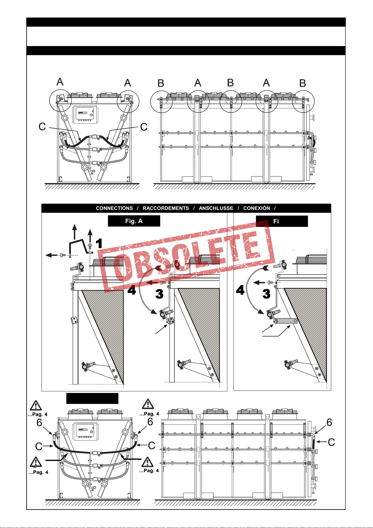
C) Prima di procedere ai collegamenti dei collettori/distributori, è obbligatorio:
1 - Personale abilitato.
2 - Assicurarsi che il circuito d’alimentazione sia chiuso (assenza di pressione).
3 - Durante l’operazione di saldatura, assicurarsi di indirizzare la fiamma in modo da non
investire la macchina (eventualmente interporre una protezione).
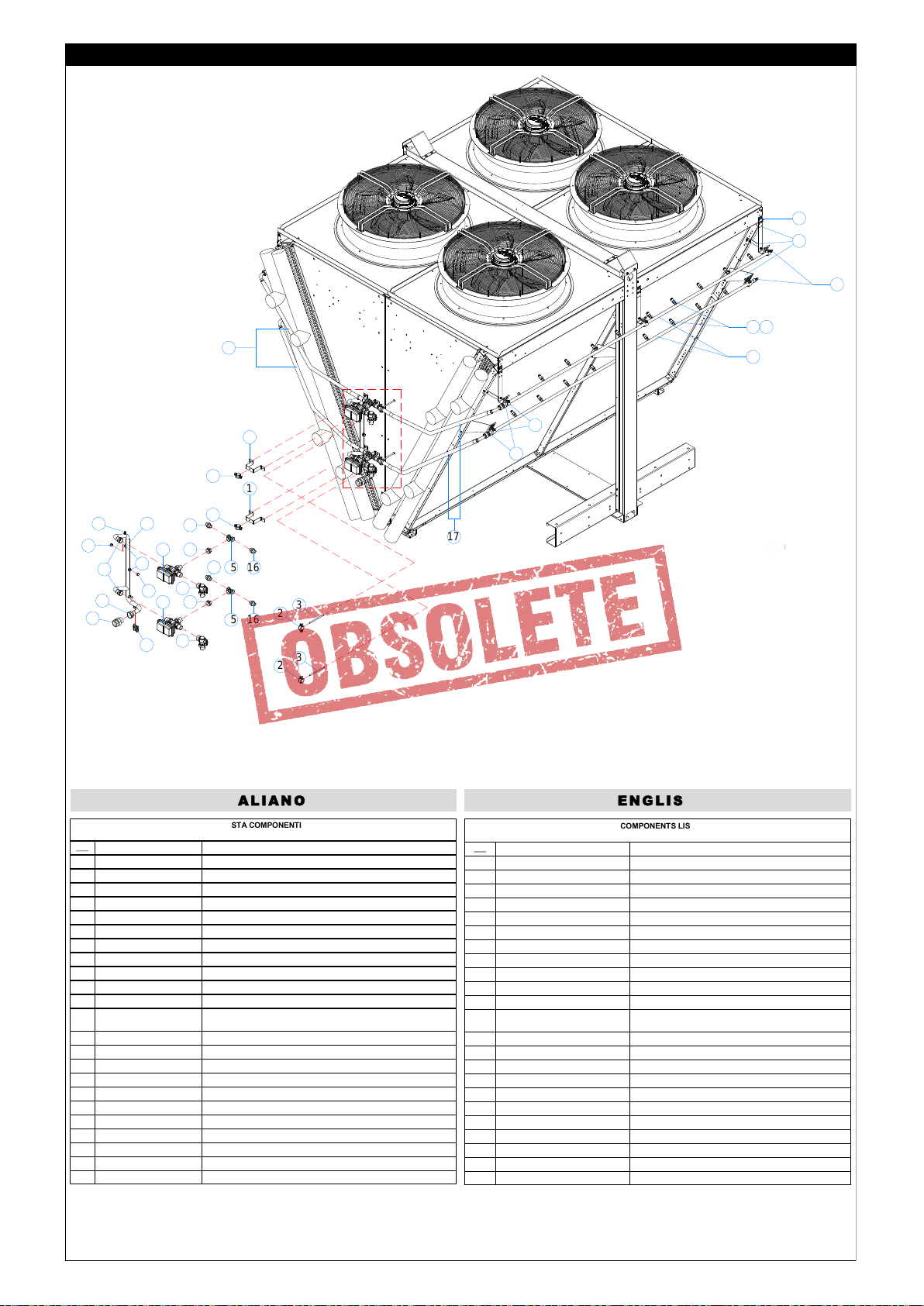
D) SMALTIMENTO: I prodotti LU-VE sono composti da:
Materiali plastici: polistirolo, ABS, gomma.
Materiali metallici: ferro, acciaio inox, rame, alluminio (eventualmente trattati).
Per i liquidi refrigeranti seguire le istruzioni dell’installatore dell’impianto.
E) Togliere la pellicola trasparente di protezione dalle parti metalliche verniciate.
F) Linee guida VDI 2047-2 “Igiene per scambiatori di calore”
STANDARDS - The products are provided for incorporation in machines as
definedi n the EC Machine Directive 2006/42/EC and subsequent modifications.
• PED 2014/68/EU
• Safety of Machinery EN 60204-1
• Directive 2014/30/EC and subsequent modifications. Electromagnetic compatibility.
• Low tension - Reference Directive 2014/35/EC
However it is forbidden to operate our equipment before the machine
incorporating the products or making part thereof has been declared to be in
conformity with the EC Machine Directive
PRECAUTIONS: guard against any injury risks or damage to
materials if these instructions are not followed.
A) For moving, installing and maintenance operations it is essential
to comply as follows:
1 - Employ authorized personnel only for using moving equipment (cranes,
forklift elevators, etc.).
2 - Wear work gloves.
3 - Never remain below suspended loads.
B) Before proceeding with electrical wiring it is essential to comply as follows:
1 - Employ only authorized personnel.
2 - Make sure the power line circuit is open.
3 - The main switch on the general power panel is open and padlocked in this position.
C) Before proceeding with the header/distributor connections it is essential to:
1 - Employ only authorized personnel
2 - Make sure the supply circuit is closed (no pressure).
3 -When performing welding operations, make sure the flame is not aimed towards the
equipment (insert a shield if required).
D)DISPOSAL: LU-VE products are made of:
Plastic materials: polyethylene, ABS, rubber.
Ferrous materials: iron, stainless steel, copper, aluminium (possibly treated).
Refrigerant liquids: follow the instructions of the system installer.
E) Remove the transparent protection film from painted metallic parts.
F) VDI 2047-2 guidelines “Hygiene for heat exchangers”
Normes: les appareils ont été conçus et fabriqués pour être incorporés dans des
machines selon la Directive Machines 2006/42/EC et les amendements successifs.
• PED 2014/68/EU
• Sécurité de la machine 60204-1
• Directive 2014/30/EC et amendements successifs. Compatibilité électromagnétique.
• Basse tension. Référence directive 2014/35/EC.
Toutefois, il est interdit de mettre nos appareils en marche avant que la machine dans
laquelle ils sont incorporés ou dont ils font partie ne soit déclarée conforme à la législa-
tion en vigueur.
PRECAUTIONS: Mise en garde contre d’éventuels risques d’accident ou d’endom-
magement des appareils en cas de non-observation des instructions.
A)
1 - L’intervention d’ un opérateur autorisé à l’ usage des appareils de manipulation
(grue, chariot élévateur, etc.).
2 - L’utilisation de gants de protection.
3 - De ne pas stationner en dessous d’une charge suspendue.
B) Avant de procéder aux raccordements électriques, il faut obligatoirement :
1 - L’intervention d’un opérateur autorisé.
2 - De s’assurer que le circuit électrique d’alimentation est ouvert.
3 - De s’assurer que l’interrupteur du boîtier général d’alimentation est bloqué par un
cadenas en position ouverte.
C) Avant de procéder aux raccordements des collecteurs/distributeurs, il faut
obligatoirement :
1 - L'intervention de personnel qualifié,
2 - S'assurer que le circuit d'alimentation est fermé (absence de pression),
3 - Lors de la soudure, s'assurer que la flamme est dirigée de façon à ne pas toucher
l'appareil (si besoin, placer une protection devant la machine).
D)ELIMINATION: Les produits LU-VE sont composés de:
Matériaux plastiques: Polystyrène, ABS, caoutchouc.
Matériaux métalliques: fer, acier inox, cuivre, aluminium (éventuellement traité).
E) Ôter la pellicule transparente de protection des parties métalliques peintes.
F) Directive VDI 2047-2 "hygiène pour les échangeurs de chaleur"
NORMEN - Die Produkte sind in Übereinstimmung mit der EG Richtlinie
2006/42/EC und nachtfolgende Ergänzungen entwickelt, konstruiert und gefertigt.
• PED 2014/68/EU
• Safety of Machinery EN 60204-1
Richtlinie 2014/30/EC und nachfolgende Ergänzungen.
• Niederspannung - Richtlinie 2014/35/EC.
Die Inbetriebnahme dieser Maschine ist so lange untersagt, bis sichergestellt ist, daß die
Anlage, in die sie eingebaut wurde oder von welcher sie ein Teil ist, den Bestimmungen
der EG Richtlinie Maschinen entspricht.
VORSICHTSMASSNAHMEN: Warnung vor Unfall- oder Materialschadensgefahren
bei Ver letzung der Vorschriften.
A) Für den Innerbetrieblichen Transport, die Installation und die
Wartung müssen folgende Vor schriften eingehalten werden:
1 - Das Personal muss für die Bedienung von innerbetrieblichen Transporteinrichtungen
und die Wartung an den in der Bedienungs- und Wartunsanleitung beschriebenen
Geräten befähigt sein.
2 - Gebrauch von Schutzhandschuhen.
3 - Kein Aufenthalt von Personen unter hängenden Lasten.
B) Vor Ausführung der Elektroanschlüsse müssen folgende Vorschriften
eingehalten werden:
1 - Fachkundiges Personal.
2 - Sicherstellen, daß der Stromversorgungskreis offen ist.
3 - Der Schalter am Hauptstromversorgungs-Schaltschrank muß mit einem Schloß
versehen und ge öffnet sein.
C) Vor Anschluss der Sammelrohre/Verteilerrohre müssen folgende Vorschriften
eingehalten werden:
1 - Fachkundiges Personal.
2 - Sicherstellen, daß der Speisungskreis geschlossen ist (kein Druck).
3 - Beim Schweißen die Flamme so ausrichten, daß die Maschine nicht getroffen wird
(eventuell mit einem Schutz versehen).
D) ENTSORGUNG: Die LU-VE-Produkte bestehen aus:
Plastmaterialien: Polystyrol, ABS, Gummi.
Metallmaterialien: Eisen, rostfreier Stahl, Kupfer, Aluminium (eventuell behandelt).
Bezüglich der Kühlflüssigkeiten
E) Die transparente Plastfolie von den lackierten Metallteilen entfernen.
F) Richtlinienreihe VDI 2047-2 “Hygiene bei Rückkühlwerken”
Referencia Directiva de Máquinas 2006/42/EC y posteriores modificaciones. Los productos
han sido diseñados y construídos para poder incorporarse en máquinas como es indicado
por la Directiva de Máquinas 2006/42/EC con sus sucesivas modificaciones y corresponden
a las siguientes normas:
• PED 2014/68/EU
• EN 60335-1 (CEI 61-50) Seguridad de los aparatos eléctricos de uso doméstico.
Normas generales.
• CEI-EN 60335-2-40 Seguridad de los aparatos de uso doméstico y similar parte 2a.
Normas especificas para bombas de calor eléctricas, sistemas de aire acondicionado y
deshumidificadores.
• Directiva 2014/30/EC y sucesivas modificaciones. Compatibilidad electromagnética.
• Baja tensión - Referencia Directiva 2014/35/EC.
No está permitido poner en marcha nuestros productos antes de que el equipo en el que son
incorporados haya sido declarado conforme a la legislación en vigor.
PRECAUCIONES: Advertencia contra eventuales riesgos de daños a personas o
materiales, en caso de que no se sigan las instrucciones.
A) Para las operaciones de manipulación, instalación y mantenimiento es obligatorio:
1- Advertir contra eventuales riesgos de daños a personas o materiales en caso de que no
se sigan las instrucciones.
2 - Personal capacitado en el uso de máquinas para la manipulación de mercancía (grúas,
elevadores, etc.).
3 - Utilizar guantes protectores.
4 - No ubicarse bajo carga suspendida.
B) Antes de que se proceda a realizar la conexión eléctrica, es necesario:
1 - Personal capacitado.
2 - Asegurarse de que el circuito de alimentación eléctrica esté abierto.
3 – Verificar que el interruptor del cuadro general esté bloqueado por una llave en
posición abierta.
C) Antes de que se proceda a realizar la conexión de los colectores/distribuidores, es
obligatorio:
1 - Personal capacitado.
2 - Asegurarse de que el circuito de alimentación esté cerrado (falta de presión).
3 - Durante la operación de soldadura, asegurarse de que la llama no se coloque en direc-
ción de la máquina (opcionalmente colocar una protección).
D) EVACUACIÓN: Los productos LU-VE se componen de:
Materiales plásticos: poliésteres, ABS, goma.
Materiales metálicos: hierro, acero inoxidable, cobre, aluminio (en algunos casos con
pre-tratamiento).
Para los líquidos refrigerantes seguir las instrucciones del instalador del proyecto.
E) Eliminar la protección plástica transparente de las partes metálicas pintadas.
F) VDI 2047-2 "Limpieza para intercambiadores de calor"
В соответствии сДирективой 2006/42/EC с учетом поправок.
изделия спроектированы и изготовлены для того чтобы они были применены в
качестве частей агрегата в соответствии с ирективой 2006/42/EC с учетом
поправок, и
• PED 2014/68/EU
• иректива 2014/30/EC с учетом поправок. Электромагнитная совместимость.
Низкое напряжение - Соответствие ирективе 2014/35/EC.
Однако, не допускается применять наши изделия в качестве частей
агрегата,прежде чем машина, частями которой они являются, будет признана
соответствующей нормам,установленным законодательством.
МЕЫПРЕДОСТОРОЖНОСТИ: При несоблюдении данных предписаний могут
произойти несчастные случаи или повреждение изделий.
A) Для погрузочно-разгрузочных операций , монтажа и технического
обслуживания ,необходимо следующее:
1 - Лерсонал квалифицирован и допущен к управлению следующими
Подъемными механизмами (подъемный кран, подъемник и т.д.).
2 - Использовать защитные перчатки.
3 - Не находиться под грузом .
B) Перед тем как произвести все электрические подключения, необходимо
удостовериться:
1 –В том, что персонал квалифицирован.
2 - Электрический контур незамкнут.
3 - Электрощит находится в доступном месте и закрыт на замок.
C)
1 - Только авторизованный персонал.
2 - Убедитесь, что контур закрыт (без давления).
3 - Во время операции сварки, убедитесь, что сопло пламя не направлено к
оборудованию (вставить щит).
D) УТИПИ3АЦИЯ: Продукция LU-VE состоит из:
Пластик: полистирол, ABS, резина.
Металл: железо, нержавеющая сталь, медь, aлюминий (обработанный).
Касательно хладагентов следует воспользоваться инструкцией по эксплуатации.
E)Снять прозрачную защитную полиэтиленовую пленку с металлических
окрашенных частей
F) VDI 2047-2 "Гигиена для теплообменников"
F R A N C A I S
E S PA Ñ O L DECLARACÍON DEL FABRICANTE P Y CC K ИЙ Заявление изготовителя
HERSTELLERERKLÄRUNG
D E U T S CH
E N G L I S H
DICHIARAZIONE DEL FABBRICANTE
I T A L I A N O

3
DRY and SPRAY
Modello / Type / Modèle XDHL - XDHV Modell / Modelo / Модель
L'impianto è composto da tubi di rame. L'ingresso idrico è effettuato attra-
verso un bocchettone in ottone da un 1-1/4” femmina.
Le rampe vengono alimentate attraverso delle elettrovalvole motorizzate
con attacco da 1” con bobine alimentate a 24 V.
Sono installate delle elettrovalvole automatiche per lo scarico dell’impianto
(installazione sul posto).
Il comando delle elettrovalvole, sia di alimentazione che scarico automatico
è gestito direttamente dalla logica di controllo del AWS.
Il numero degli ugelli per impianto std è di n°8 per modulo n° 4 per batteria
destra, n° 4 per batteria sinistra.
Gli ugelli sono in ottone (tipo LMP02).
L'impianto è fornito completo in tutte le sue parti, e con le rampe smontate
(vedi pos. 1) per farle rientrare nelle dimensioni max dell'apparecchio per il
trasporto.
Per il pronto utilizzo eseguire il montaggio delle rampe come rappre-
sentato in fig. 1.
Il cliente all'occorrenza può ruotare l'intera rampa per ottimizzare la direzio-
ne dello spruzzo, infatti le rampe sono collegate tramite raccordi che ne
permettono la rotazione.
The unit is constructed using copper tubes. Water enters through a 1-1/4”
female brass pipe union.
The ramps are fed by 1” attachment electro-valves with coils operating on
24V.
Automatic valves are installed on the discharging (installation on site).
The control of the electro-valves, both for supply and automatic draining,
are governed directly by the logic of the WS control.
The number of nozzles per standard unit is 8 per module, 4 for the left coil
and 4 for the right coil.
The nozzles are made of brass (type MP02).
The unit is supplied with all parts, with the racks unassembled.(see position
1) so that they stay within the maximum dimensions of the equipment for
transportation.
For first time use, fit the upper ramps as shown in fig.1.
If required, the customer can rotate the entire ramp in order to optimize the
direction of the spray. The ramps are connected by joints which enable this
rotation.
I T A L I A N O E N G L I S H
L'installation est réalisée en tubes de cuivre. Le raccordement hydraulique
s'effectue par un embout en laiton de 1-1/4” femelle.
Les rampes sont alimentées par des électrovannes motorisées avec un
raccord 1 '' avec des bobines alimentées en 24 V.
Les vannes automatiques sont installées sur l'évacuation (installation sur le
site).
La commande des électrovannes, soit d'alimentation, soit de purge automa-
tique, est gérée directement par le système de contrôle AWS.
En installation standard, il y a 8 buses par module, 4 pour la batterie droite
et 4 pour la batterie gauche. Les buses sont en laiton (type LMP02).
L’installation est complète et fournie avec les rampes démontées (voir
position 1) pour respecter les contraintes dimensionnelles lors du transport
de l’appareil.
Avant utilisation, il faut faire tourner les rampes comme indiqué sur le
Fig. 1.
Le client, en cas de besoin, peut faire pivoter la rampe entière pour optima-
liser la direction de la nébulisation, en effet, les rampes sont reliées par
des accords qui permettent la rotation.
Die Anlage besteht aus Kupferrohren. Der Wasserzulauf erfolgt durch über
ein Kupferohr mit 1-1/4'' -Innengewinde.
Die Sprühlanzen werden durch Magnetventile mit einem 1''-Anschluss und
24V Spulen versorgt.
Automatische Ventile werden am Ablauf installiert. (zum bauseitigen Ein-
bau).
Die Steuerung der Magnetventile sowohl für die Einspeisung wie auch für
die automatissche Entleerung wird direkt durch die Steuerlogik des AWS
gesteuert. Die Anzahl der Sprühdüsen für eine Standardanlage beträgt 8
Stück pro Modul, 4 für den rechten und 4 für den linken Wärmetauscher.
Die Sprühdüsen sind aus Messing (Typ LMP02). Die Anlage wird komplett
und mit nicht montierten Rampen
geliefert (siehe Pos.1), damit sie die max. Geräteabmessungen für den
Transport nicht überschreiten.
Der Kunde kann bei Bedarf zur Optimierung der Sprührichtung die
gesamte Rampe drehen; die Rampen sind durch drehbare An-
schlussstücke verbunden.
Der Kunde kann, wenn notwendig, die gesamte Rampe drehen, um die
Richtung des Sprühnebels zu optimieren, in der Tat sind die Rampen durch
Armaturen verbunden, um die Drehung zu ermöglichen.
F R A N C A I S D E U T S C H
INSTALLAZIONE / INSTALLATION / INSTALLATION / MONTAGE / MONTAJE / ИНСТАЛЛЯЦИЯ
NA
● In fase di installazione, prevedere un inclinazione del 2%
● During the installation stage, to provide for a tilt of 2%
● Au cours de la phase d'installation, de prévoir une inclinaison de 2%
● Während der Installationsphase , für eine Neigung von 2% zu liefern
● Durante la fase de instalación, para proporcionar una inclinación del 2%
● На стадии монтажа, чтобы обеспечить наклоне 2%

4
Modello / Type / Modèle XDHL - XDHV Modell / Modelo / Модель
El equipo está compuesto por tubos de cobre. El agua ingresa través de
un difusor de latón de 1-1/4” hembra.
Las rampas se alimentan por medio de electroválvulas con conexión de 1”
y bobinas a 24 V.
Máquina provista de electroválvulas para facilitar la descarga (instalación
en el lugar) El control de las electroválvulas, tanto de alimentación como de
vaciado automático es gestionado directamente por una lógica de control
del WS.
El número de difusores por cada equipo standard es de 8 unidades por
módulo, 4 para el intercambiador del lado derecho, y 4 para el intercambia-
dor del lado izquierdo.
Los difusores son de latón (tipo LMP02).El equipo se suministra con todos
sus componentes y con las rampas de difusión desmontadas (ver pos. 1)
para facilitar el transporte.
Para utilizar el equipo es necesario ejecutar el montaje de las rampas
como es indicado en la Fig. 1.
En el caso de que sea necesario, el cliente puede rotar toda la rampa para
optimizar la dirección de la nebulización del agua; de hecho, las rampas
están conectadas por medio de juntas que facilitan su rotación.
Агрегат состоит из медных труб. Жидкость входит через латунный
разъём размером 1-1/4”.(F).
Hитание ёмкостей системы происходит через электромагнитные
клапаны с подсоединением в 1” с катушкой под напряжением 24B.
Как дополнительная опция, могут быть установлены электромагнитные
клапаны с автоматическим сливом.
Управление работой электромагнитных клапанов, как питание,
так и автоматический слив, производится непосредственно
центральным контроллером системы.
Количество насадок предназначенных для стандартной установки это
8шт для каждого модуля, из них 4 для правой баттареи и 4 для левой
батареи. Bасадки изготовлены из латуни (мод. LMP02). Все
компоненты установки поставляются с заказом. Pазветвления
установки поставляются в разобранном виде (см.поз.1), так чтобы они
входили в размеры оборудования во время транспортировки.
Пользователь при необходимости может повернуть все рампы для
оптимизации направления разбрызгивания, т.к они связаны с помощью
соединений, которые позволяют их вращение.
ESPAÑ O L Р У С С К И Й
NC
Elettrovalvola motorizzata
Motorised electro-valve
Electrovanne d’alimentation
Motorventil
Electrovàlvula motorizada
Электромагнитный клапан
с приводом
NA
Elettrovalvole per drenaggio
Draining electro-valve
Electrovanne de vidange
Magnetventil zur Entleerung
Electrovàlvulas para el vaciado
Электромагнитный клапан
для дренажа
OPTIONAL
ATTENZIONE / CAUTION / ATTENTION / ACHTUNG / ATENCION / ВНИМАНИЕ
ДА
ДА

5
DRY and SPRAY
Modello / Type / Modèle EHLD - EHVD Modell / Modelo / Модель
INSTALLAZIONE / INSTALLATION / INSTALLATION / MONTAGE / MONTAJE / ИНСТАЛЛЯЦИЯ
● In fase di installazione, prevedere un inclinazione del 2%
● During the installation stage, to provide for a tilt of 2%
● Au cours de la phase d'installation, de prévoir une inclinaison de 2%
● Während der Installationsphase , für eine Neigung von 2% zu liefern
● Durante la fase de instalación, para proporcionar una inclinación del 2%
● На стадии монтажа, чтобы обеспечить наклоне 2%
COLLEGAMENTI / CONNECTIONS / RACCORDEMENTS / ANSCHLUSSE / CONEXIÓN / ПОДСОЕДИНЕНИЕ
Fig. B
5
4
3
Fig. A
5
4
3
1
1
2
Fig. C

6
DRY and SPRAY
COMPONENTS LIST
DRY & SPRAY SYSTEM FOR EHVD - EHLD 3V UNITS
No. Component description Material
1Metal bracket Zinc plated and painted carbon steel
2Tube support Stainless steel and rubber
3Threaded rod Stainless steel
4Schrader valve Brass
5Header Copper smooth pipe Ø22x1,5 VLC CU DHP H2O
6Stopper Brass
7Threaded pipe union Nickeled brass
8Welded threaded pipe union Bronze
9Welded threaded pipe union Brass
10 Welded threaded pipe union Brass
11 Ball valve Brass
12 Three way valve Outer shell: polymer “Polyarylamide” glass filled. External
metal parts: AISI303 GVR and brass CW617N.
Body: brass CW617N UNI 5705
13 Ball valve Brass
14 Nipple Brass
15 Threaded T-connection Brass
16 Nipple Brass
17 flexible coupling AISI 304
18 Threaded pipe connection Chrome steel
19 Ramp Copper smooth pipe Ø22x1,5 VLC CU DHP H2O
20 Nozzle Brass
21 Holder for nozzle Brass
22 Metal bracket Zinc plated and painted carbon steel
23 Hinge AISI 304
LISTA COMPONENTI
PER SISTEMI DRY & SPRAY EHVD - EHLD 3V
No. Descrizione componenti Materiale
1Staffa metallica Acciaio al carbonio zincato e verniciato
2Supporto tubazione Acciaio inox e gomma
3Asta filettata Acciaio inox
4Valvola Schrader Ottone
5Testata Tubo in Rame morbido Ø22x1,5 VLC CU DHP H2O
6Tappo Ottone
7Bocchettone filettato Ottone Nichelato
8Raccordo filettato a saldare Bronzo
9Raccordo filettato a saldare Ottone
10 Raccordo filettato a saldare Ottone
11 Valvola a sfera Ottone
12 Valvola tre vie Calotta esterna: polimero di vetro pieno “Poliacrilammide”. Parti
esterne metalliche: AISI303 GVR e ottone CW617N.
Corpo: ottone CW617N UNI 5705
13 Valvola a sfera Ottone
14 Nipplo Ottone
15 Connettore a “T” filettato Ottone
16 Nipplo Ottone
17 Giunti flessibili AISI 304
18 Raccordo filettato Acciaio cromato
19 Rampa Tubazione in Rame morbido Ø22x1,5 VLC CU DHP H2O
20 Ugello Ottone
21 Supporto ugello Ottone
22 Staffa metallica Acciaio al carbonio zincato e verniciato
23 Cerniera AISI 304
20 21
19
4
1
7
21
2
23
23
5
6
6
11
4
12 14
16
1615
14
16
1615
12 13
13
18
2
8
910
17
17
22
23
ITA LIANO ENG L IS H

7
DRY and SPRAY
No.
1
2
3
4
5
6
7
8
9
10
11
12
13
14
15
16
17
18
19
20
21
22
23
LISTA DE COMPONENTES
PARA SISTEMAS DRY & SPRAY EHVD - EHLD 3V
No. Descripción de los compo-
nentes Material
1Soporte metálico Acero al carbono zincado y vernizado
2Soporte tubo Acero inoxidable y goma
3Varilla roscada Acero inoxidable
4Válvula Schrader Latón
5Cabezal Tubo de cobre liso Ø22x1,5 VLC CU DHP H2O
6Tapón Latón
7Tubo roscado Latón Niquelado
8Tubo roscado para soldar Bronce
9Tubo roscado para soldar Latón
10 Tubo roscado para soldar Latón
11 Válvula de esfera Latón
12 Válvula 3 vias Carcaza externa: polímero de vidrio “Poliacrilamida”. Partes externas
metálicas: AISI303 GVR y Latón CW617N.
Cuerpo: Latón CW617N UNI 5705
13 Válvula de esfera Latón
14 Niple de Reducción Latón
15 Conector a “T” roscado Latón
16 Niple de Reducción Latón
17 Junta flexible AISI 304
18 Tubo roscado Acero cromado
19 Rampa Tubo de cobre liso Ø22x1,5 VLC CU DHP H2O
20 Difusor Latón
21 Soporte difusor Latón
22 Soporte metalico Acero al carbono zincado y vernizado
23 Bisagra AISI 304
ESP A ÑO L Р Υ С С К И Й
TEILLISTE
SPRÜHSYSTEME FÜR TROCKENE & EHVD - EHLD 3V
No. Komponentenbeschreibung Material
1Metallhalterung Verzinktes pulverbeschichtetes Stahlblech
2Rohraufnahme Edelstahl und Gummi
3Gewindestange Edelstahl
4Schraderventil Messing
5Header Kupfer weich
6Stopper Messing
7Rohrverschraubung Vernickeltes Messing
8Geschweißte Rohrverbindung Bronce
9Geschweißte Rohrverbindung Messing
10 Geschweißte Rohrverbindung Messing
11 Kugeventil Messing
12 3 - Wege - Ventil Polymerplastik, AISI 303,
Messing
13 Kugelventil Messing
14 Nippel Messing
15 Geschraubte T-Verbindung Messing
16 Nippel Messing
17 Flexibler Schlauchanschluss AISI 304
18 Geschraubte Rohrverbindung Verchromter Stahl
19 SPrühsystemverrohrung Kupfer weich
20 Düse Messing
21 Düsenhalter Messing
22 Metallhalterung Verzinktes pulverbeschichtetes Stahlblech
23 Gelenk AISI 304
LISTE COMPOSANTS
POUR SYSTÈMES DRY & SPRAY EHVD– EHLD 3V
No. Description composants Matériel
1Support métallique Acier au carbone galvanisé et peint
2Support tuyauterie Acier inox et caoutchouc
3Tige filetée Acier inox
4Vanne Schrader Laiton
5Tête Tuyau en cuivre tendre Ø 22X1,5 VLC CU DHP H20
6Bouchon Laiton
7Embout fileté Laiton en nickel
8Raccord fileté à souder Bronze
9Raccord fileté à souder Laiton
10 Raccord fileté à souder Laiton
11 Vanne sphérique Laiton
12 Vanne troies voies Logement externe: polymère fibre de verre plein”polyacrylammide”.
Parties externes métalliques: AISI303 GVR et laiton CW617N. Corp:
Laiton CW&17N UNI 5705
13 Vanne sphérique Laiton
14 Raccord/barette Laiton
15 Raccord en “Té fileté Laiton
16 Raccord/Barette Laiton
17 Accouplements flexibles AISI 304
18 Raccord fileté Acier chromé
19 Rampe Tuyauterie en cuivre tendre Ø 22X 1,5 VLC CU DHP H20
20 Buse Laiton
21 Support buse Laiton
22 Support métallique Acier au carbone galvanisé et peint
23 Charnière AISI 304
FRA N CA IS DEU T SC H

8
NC
Elettrovalvola motorizzata
Motorised electro-valve
Electrovanne d’alimentation
Motorventil
Electrovàlvula motorizada
Электромагнитный клапан
с приводом
Elettrovalvole per drenaggio
Draining electro-valve
Electrovanne de vidange
Magnetventil zur Entleerung
Electrovàlvulas para el vaciado
Электромагнитный клапан
для дренажа
NA
Modello / Type / Modèle EHLD - EHVD Modell / Modelo / Модель
L'impianto è composto da tubi di rame e in acciaio inox. L'ingresso idrico è
effettuato attraverso un bocchettone in ottone da un 1-1/4” femmina.
Le rampe vengono alimentate attraverso delle elettrovalvole motorizzate
con attacco da 1” con bobine alimentate a 24 V.
Sono installate delle elettrovalvole automatiche per lo scarico dell’impianto.
Il comando delle elettrovalvole, sia di alimentazione che scarico automatico
è gestito direttamente dalla logica di controllo del AWS.
Il n° degli ugelli per impianto std è di 5 per modulo batteria e per rampa
superiore e di n°4 per modulo e per rampa inferiore.
Gli ugelli sono in ottone (tipo LMP02).
L'impianto è fornito completo in tutte le sue parti, e con le rampe superiori
ruotate verso l’alto per farle rientrare nelle dimensioni max dell'apparecchio
per il trasporto.
Per il pronto utilizzo occorre ruotare le rampe superiori (Fig A) e fis-
sarle ai profili di sostegno (Fig B); quindi vanno collegati i tubi in
acciaio inox al manicotto (Fig C). Controllare che i tubi in acciaio inox
siano ben tesi e non facciano pance, agendo sul bocchettone 6, al fine
di garantire un corretto svuotamento.
Il cliente all'occorrenza puo' ruotare l'intera rampa per ottimizzare la direzio-
ne dello spruzzo, infatti le rampe sono collegate tramite raccordi che ne
permettono la rotazione.
The unit is constructed using copper and stainless steel tubes. Water enters
through a 1-1/4” female brass pipe union.
The ramps are fed by 1” attachment motorized electro-valves with coils
operating on 24V.
automatic valves are installed on the discharging.
The control of the electro-valves, both for supply and automatic draining,
are governed directly by the logic of the AWS control.
The number of nozzles for standard units is 4 for the coil module and the
upper rack, 3 for the intermediate module and rack and 2 for the lower rack.
The nozzles are brass (LMP02 type).
The unit is supplied complete in all its parts, with the upper ramps turned
upwards so that they come within the maximum dimensions of the unit for
transportation.
Preparation for immediate use requires the upper ramps to be rotated
(Fig A) and attached to the support profiles (Fig B); then the stainless
steel tubes are connected to the sleeve (Fig C). Make sure that the
stainless steel tubes are taut and do not sag, using threaded pipe
union 6 to ensure correct emptying.
If required, the customer can rotate the entire ramp in order to optimize the
direction of the spray. The ramps are connected by joints which enable this
rotation.
I T A L I A N O E N G L I S H
L'installation est réalisée en tubes de cuivre et acier inoxydable. Le raccor-
dement hydraulique s'effectue par un embout en laiton de 1-1/4” femelle.
Les rampes sont alimentées par des électrovannes motorisées avec un
raccord 1 '' avec une bobine alimentée en 24 V.
Les vannes automatiques sont installées sur l'évacuation.
La commande des électrovannes, soit d'alimentation, soit de purge automa-
tique, est gérée directement par le système de contrôle AWS.
En implantation standard il y a 5 buses par module de batterie et par rampe
supérieure, et 4 par module et par rampe inférieure.
Les buses sont en laiton, type LMP02.
L'installation est complète, mais les rampes supérieures sont tournées vers
le haut pour respecter les dimensions maxi. de l'appareil pour le transport.
Pour l’installation finale, il faut tourner les rampes supérieures (Fig A)
et les fixer aux dispositifs de soutien( fig B); Puis, raccorder les tubes
en acier inoxydable au manchon/la gaine (Fig C). Contrôler que les
tubes en acier inoxydable sont bien tendus et qu’ils ne se plient pas
en utilisant l’embout 6 afin de garantir une vidange correcte.
Le client, en cas de besoin, peut faire pivoter la rampe entière pour optima-
liser la direction de la nébulisation, en effet, les rampes sont reliées par
des accords qui permettent la rotation.
Die Anlage besteht aus Kupfer- und Edelstahlwellrohren. Der Wasserzulauf
erfolgt durch Einlaufstutzen aus Kupfer mit 1-1/4'' -Innengewinde.
Die Rampen werden durch Elektroventile mit einem 1''-Anschluss mit bei
24V betriebenen Spulen gespeist.
Automatische Ventile werden am Ablauf installiert. (zum bauseitigen Ein-
bau).
Die Steuerung der Elektroventile sowohl für die Einspeisung als auch für
die automatische Entleerung wird direct durch die Steuerlogik des AWS
gesteuert.
Die Anzahl der Düsen für die Standard-Anlage ist 5 pro Batteriemodul und
für die obere Rampe und 4 pro Modul und für die untere Rampe.
Die Düsen sind aus Kupfer (Typ LMP02).
Die Anlage wird komplett mit allen Teilen geliefert, wobei die oberen Ramp-
en nach oben gedreht sind, damit sie innerhalb der Maximalabmessungen
des Geräts für den Transport bleiben.
Zum Betrieb die oberen Rampen (Abb. A) drehen und an den Stützpro-
filen (Abb.B) befestigen, anschließend werden die Edelstahlschläuche
an der Muffe ( C ) befestigt. Es ist sicherzustellen, dass die Edelstahl-
schläuche straff sind und nicht durchhängen. Durch Einwirken auf
Stutzen 6 kann die korrekte Entleerung gewährleistet werden.
Der Kunde kann bei Bedarf zur Optimierung der Sprührichtung die gesamte
Rampe drehen; die Rampen sind durch drehbare Anschlussstücke verbun-
den.
F R A N C A I S D E U T S C H
El equipo está compuesto por tubos de cobre y acero inoxidable. El agua
entra a través de un difusor de latón de 1-1/4” hembra.
Las rampas se alimentan por medio de electroválvulas con conexión de 1”
y bobinas a 24 V.
Máquina provista de electroválvulas para facilitar la descarga.
El control de las electroválvulas, tanto de alimentación como de vaciado
automático es gestionado directamente por una lógica de control del WS.
El número de difusores por cada equipo es de 5 unidades por módulo
batería /rampa superior y de 4 unidades por módulo y rampa inferior.
Los difusores son de latón (tipo LMP02).El equipo se suministra con todos
sus componentes y con las rampas de difusión desmontadas (ver pos. 1)
para facilitar el transporte.
Para utilizar el equipo inmediatamente es necesario rotar las rampas
superiores (Fig A) y fijarlas a los perfiles de soporte (Fig B), es decir,
los tubos en acero inoxidable deben estar conectados al casquillo
(Fig C). Asegúrese de que los tubos en acero inoxidable estén com-
pletamente fijos, para ello utilice uniones 6 para garantizar un correc-
to vaciado.
En el caso de que sea necesario, el cliente puede rotar toda la rampa para
optimizar la dirección de la nebulización del agua; de hecho, las rampas
están conectadas por medio de juntas que facilitan su rotación.
Агрегат состоит из медных труб и нержавеющая сталь трубки.
Жидкость входит через латунный разъём размером 1-1/4”.(F).
Питание ёмкостей системы происходит через электромагнитные
клапаны с подсоединением в 1” с катушкой под напряжением 24В.
Как дополнительная опция, могут быть установлены электромагнитные
клапаны с автоматическим сливом. Управление работой
электромагнитных клапанов, как питание, так и автоматический слив,
производится непосредственно центральным контроллером системы.
Стандартное количество насадок для установки - 5 модулей для
верхней рампы, и 4 модуля в нижней рампе.
Насадки сделаны из латуни (тип LMP02).
Агрегат поставляется в полной комплектации, с верхними рампами
повёрнутыми вверх для наибольшей компактности во время
перевозки.
Для быстрого использования, необходимо повернуть верхние
магистрали (рис.А) и прикрепить к опорным профилям (рис. B); затем
нержавеющая стальтрубки соединить с разьемом (рис. C) . Убедитесь,
что нержавеющая сталь трубки натянуты и не провисают, используя
резьбовое соединение труб, для правильного слива.
Пользователь при необходимости может повернуть все рампы
для оптимизации направления разбрызгивания, т.к они связаны с
помощью соединений, которые позволяют их вращение.
E S P A Ñ O L Р У С С К ИЙ

9
Modello / Type / Modèle XXLD - XXVD Modell / Modelo / Модель
INSTALLAZIONE / INSTALLATION / INSTALLATION / MONTAGE / MONTAJE / ИНСТАЛЛЯЦИЯ
DRY and SPRAY
COLLEGAMENTI / CONNECTIONS / RACCORDEMENTS / ANSCHLUSSE / CONEXIÓN / ПОДСОЕДИНЕНИЕ
Fig. A Fig. B
5
4 3
5
4 3
1
1
2
● In fase di installazione, prevedere un inclinazione del 2%
● During the installation stage, to provide for a tilt of 2%
● Au cours de la phase d'installation, de prévoir une inclinaison de 2%
● Während der Installationsphase , für eine Neigung von 2% zu liefern
● Durante la fase de instalación, para proporcionar una inclinación del 2%
● На стадии монтажа, чтобы обеспечить наклоне 2%
Fig. C

10
DRY and SPRAY
COMPONENTS LIST
DRY & SPRAY SYSTEM FOR EHVD - EHLD 3V UNITS
No. Component description Material
1Metal bracket Zinc plated and painted carbon steel
2Tube support Stainless steel and rubber
3Threaded rod Stainless steel
4Schrader valve Brass
5Header Copper smooth pipe Ø22x1,5 VLC CU DHP H2O
6Stopper Brass
7Threaded pipe union Nickeled brass
8Welded threaded pipe union Bronze
9Welded threaded pipe union Brass
10 Welded threaded pipe union Brass
11 Ball valve Brass
12 Three way valve Outer shell: polymer “Polyarylamide” glass filled. External
metal parts: AISI303 GVR and brass CW617N.
Body: brass CW617N UNI 5705
13 Ball valve Brass
14 Nipple Brass
15 Threaded T-connection Brass
16 Nipple Brass
17 flexible coupling AISI 304
18 Threaded pipe connection Chrome steel
19 Ramp Copper smooth pipe Ø22x1,5 VLC CU DHP H2O
20 Nozzle Brass
21 Holder for nozzle Brass
22 Metal bracket Zinc plated and painted carbon steel
23 Hinge AISI 304
LISTA COMPONENTI
PER SISTEMI DRY & SPRAY EHVD - EHLD 3V
No. Descrizione componenti Materiale
1Staffa metallica Acciaio al carbonio zincato e verniciato
2Supporto tubazione Acciaio inox e gomma
3Asta filettata Acciaio inox
4Valvola Schrader Ottone
5Testata Tubo in Rame morbido Ø22x1,5 VLC CU DHP H2O
6Tappo Ottone
7Bocchettone filettato Ottone Nichelato
8Raccordo filettato a saldare Bronzo
9Raccordo filettato a saldare Ottone
10 Raccordo filettato a saldare Ottone
11 Valvola a sfera Ottone
12 Valvola tre vie Calotta esterna: polimero di vetro pieno “Poliacrilammide”. Parti
esterne metalliche: AISI303 GVR e ottone CW617N.
Corpo: ottone CW617N UNI 5705
13 Valvola a sfera Ottone
14 Nipplo Ottone
15 Connettore a “T” filettato Ottone
16 Nipplo Ottone
17 Giunti flessibili AISI 304
18 Raccordo filettato Acciaio cromato
19 Rampa Tubazione in Rame morbido Ø22x1,5 VLC CU DHP H2O
20 Ugello Ottone
21 Supporto ugello Ottone
22 Staffa metallica Acciaio al carbonio zincato e verniciato
23 Cerniera AISI 304
20 21
19
4
1
7
21
2
23
23
5
6
6
11
4
12 14
16
1615
14
16
1615
12 13
13
18
2
8
910
17
17
22
23
ITA LIANO ENG L IS H

11
DRY and SPRAY
No.
1
2
3
4
5
6
7
8
9
10
11
12
13
14
15
16
17
18
19
20
21
22
23
LISTA DE COMPONENTES
PARA SISTEMAS DRY & SPRAY EHVD - EHLD 3V
No. Descripción de los compo-
nentes Material
1Soporte metálico Acero al carbono zincado y vernizado
2Soporte tubo Acero inoxidable y goma
3Varilla roscada Acero inoxidable
4Válvula Schrader Latón
5Cabezal Tubo de cobre liso Ø22x1,5 VLC CU DHP H2O
6Tapón Latón
7Tubo roscado Latón Niquelado
8Tubo roscado para soldar Bronce
9Tubo roscado para soldar Latón
10 Tubo roscado para soldar Latón
11 Válvula de esfera Latón
12 Válvula 3 vias Carcaza externa: polímero de vidrio “Poliacrilamida”. Partes externas
metálicas: AISI303 GVR y Latón CW617N.
Cuerpo: Latón CW617N UNI 5705
13 Válvula de esfera Latón
14 Niple de Reducción Latón
15 Conector a “T” roscado Latón
16 Niple de Reducción Latón
17 Junta flexible AISI 304
18 Tubo roscado Acero cromado
19 Rampa Tubo de cobre liso Ø22x1,5 VLC CU DHP H2O
20 Difusor Latón
21 Soporte difusor Latón
22 Soporte metalico Acero al carbono zincado y vernizado
23 Bisagra AISI 304
ESP A ÑO L РΥС СКИ Й
TEILLISTE
SPRÜHSYSTEME FÜR TROCKENE & EHVD - EHLD 3V
No. Komponentenbeschreibung Material
1Metallhalterung Verzinktes pulverbeschichtetes Stahlblech
2Rohraufnahme Edelstahl und Gummi
3Gewindestange Edelstahl
4Schraderventil Messing
5Header Kupfer weich
6Stopper Messing
7Rohrverschraubung Vernickeltes Messing
8Geschweißte Rohrverbindung Bronce
9Geschweißte Rohrverbindung Messing
10 Geschweißte Rohrverbindung Messing
11 Kugeventil Messing
12 3 - Wege - Ventil Polymerplastik, AISI 303,
Messing
13 Kugelventil Messing
14 Nippel Messing
15 Geschraubte T-Verbindung Messing
16 Nippel Messing
17 Flexibler Schlauchanschluss AISI 304
18 Geschraubte Rohrverbindung Verchromter Stahl
19 SPrühsystemverrohrung Kupfer weich
20 Düse Messing
21 Düsenhalter Messing
22 Metallhalterung Verzinktes pulverbeschichtetes Stahlblech
23 Gelenk AISI 304
LISTE COMPOSANTS
POUR SYSTÈMES DRY & SPRAY EHVD– EHLD 3V
No. Description composants Matériel
1Support métallique Acier au carbone galvanisé et peint
2Support tuyauterie Acier inox et caoutchouc
3Tige filetée Acier inox
4Vanne Schrader Laiton
5Tête Tuyau en cuivre tendre Ø 22X1,5 VLC CU DHP H20
6Bouchon Laiton
7Embout fileté Laiton en nickel
8Raccord fileté à souder Bronze
9Raccord fileté à souder Laiton
10 Raccord fileté à souder Laiton
11 Vanne sphérique Laiton
12 Vanne troies voies Logement externe: polymère fibre de verre plein”polyacrylammide”.
Parties externes métalliques: AISI303 GVR et laiton CW617N. Corp:
Laiton CW&17N UNI 5705
13 Vanne sphérique Laiton
14 Raccord/barette Laiton
15 Raccord en “Té fileté Laiton
16 Raccord/Barette Laiton
17 Accouplements flexibles AISI 304
18 Raccord fileté Acier chromé
19 Rampe Tuyauterie en cuivre tendre Ø 22X 1,5 VLC CU DHP H20
20 Buse Laiton
21 Support buse Laiton
22 Support métallique Acier au carbone galvanisé et peint
23 Charnière AISI 304
FRA N CA IS DEU T SC H

12
NC
Elettrovalvola motorizzata
Motorised electro-valve
Electrovanne d’alimentation
Motorventil
Electrovàlvula motorizada
Электромагнитный клапан
с приводом
Elettrovalvole per drenaggio
Draining electro-valve
Electrovanne de vidange
magnetventil zur Entleerung
Electrovàlvulas para el vaciado
Электромагнитный клапан
для дренажа
Modello / Type / Modèle EHLD - EHVD Modell / Modelo / Модель
L'impianto è composto da tubi di rame e in gomma. L'ingresso idrico è
effettuato attraverso un bocchettone in ottone da un 1-1/4” femmina.
Le rampe vengono alimentate attraverso delle elettrovalvole motorizzate
con attacco da 1” con bobine alimentate a 24 V.
Sono installate delle elettrovalvole automatiche per lo scarico dell’impianto.
Il comando delle elettrovalvole, sia di alimentazione che scarico automatico
è gestito direttamente dalla logica di controllo del AWS.
Il n° degli ugelli per impianto std è di 4 per modulo batteria e per rampa
superiore, di n° 3 per modulo e per rampa intermedia e di n° 2 per rampa
inferiore. Gli ugelli sono in ottone (tipo LMP02).
L'impianto è fornito completo in tutte le sue parti, e con le rampe superiori
ruotate verso l’alto per farle rientrare nelle dimensioni max dell'apparecchio
per il trasporto.
Per il pronto utilizzo occorre ruotare le rampe superiori (Fig A) e fis-
sarle ai profili di sostegno (Fig B); quindi vanno collegati i tubi in
acciaio inox il manicotto (Fig C). Controllare che i tubi in acciaio inox
siano ben tesi e non facciano pance, agendo sul bocchettone 6, al fine
di garantire un corretto svuotamento.
Il cliente all'occorrenza puo' ruotare l'intera rampa per ottimizzare la direzio-
ne dello spruzzo, infatti le rampe sono collegate tramite raccordi che ne
permettono la rotazione.
The unit is constructed using copper tubes and stainless steel tubes. Water
enters through a 11/4” female brass pipe union.
The ramps are fed by 1” attachment electro-valves with coils operating on
24V.
automatic valves are installed on the discharging.
The control of the electro-valves, both for supply and automatic draining,
are governed directly by the logic of the AWS.control.
The number of nozzles for standard units is 4 for the coil module and the
upper rack, 3 for the intermediate module and rack and 2 for the lower rack.
The nozzles are brass (LMP02 type).
The unit is supplied complete in all its parts. The upper ramps are turned up
wards so that they come within the maximum dimensions of the unit for
transportation.
Preparation for immediate use requires the upper ramps to be rotated
(Fig A)and attached to the support profiles (Fig B); then the stainless
steel tubes are connected to the sleeve (Fig C). Make sure that the the
stainless steel tubes are taut and do not sag, using threaded pipe union
6 to ensure correct emptying.
If required, the customer can rotate the entire ramp in order to optimize the
direction of the spray. The ramps are connected by joints which enable this
rotation.
ITA LIANO ENG LIS H
L'installation est réalisée en tubes de cuivre et acier inoxydable. Le raccor-
dement hydraulique s'effectue par un embout en laiton de 1-1/4” femelle.
Les rampes sont alimentées par des électrovannes motorisées avec un
raccord 1 '' avec une bobine alimentée en 24 V.
Les vannes automatiques sont installées sur l'évacuation.
La commande des électrovannes, soit d'alimentation, soit de purge automa-
tique, est gérée directement par le système de contrôle AWS.
En installation standard, il y a 4 buses par module de batterie et par rampe
supérieure, 3 par module et par rampe intermédiaire et 2 par rampe inféri-
eure.
Les buses sont en laiton, type LMP02.
L'installation est complète, mais les rampes supérieures sont tournées vers
le haut pour respecter les dimensions maxi. de l'appareil pour le transport.
Pour l’installation finale, il faut tourner les rampes supérieures (Fig A)
et les fixer aux dispositifs de soutien( fig B); Puis, raccorder les tubes
en acier inoxydable au manchon/la gaine(Fig C). Contrôler que les
tubes en acier inoxydable sont bien tendus et qu’ils ne se plient pas en
utilisant l’embout 6 afin de garantir une vidange correcte.
Le client, en cas de besoin, peut faire pivoter la rampe entière pour optimali-
ser la direction de la nébulisation, en effet, les rampes sont reliées par des
accords qui permettent la rotation.
Die Anlage besteht aus Kupferrohren und Edelstahlwellrohren. Der Wasser-
zulauf erfolgt durch Einlaufstutzen aus Kupfer mit 1-1/4'' -Innengewinde.
Die Rampen werden durch Elektroventile mit einem 1''-Anschluss mit bei
24V betriebenen Spulen gespeist.
Automatische Ventile werden am Ablauf installiert.
Die Steuerung der Elektroventile sowohl für die Einspeisung als auch für
die automatische Entleerung wird direct durch die Steuerlogik des AWS
gesteuert.
Die Anzahl der Sprühdüsen pro Standardanlage betägt 4 Stück pro Wärme-
tauschermodul und pro oberer Rampe, 3 Stück pro Modul und mittlerer
Rampe und 2 Stück pro unterer Rampe.
Die Düsen sind aus Kupfer (Typ LMP02).
Die Anlage wird komplett mit allen Teilen geliefert, wobei die oberen Ramp-
en nach oben gedreht sind, damit sie innerhalb der Maximalabmessungen
des Geräts für den Transport bleiben.
Edelstahlwellrohren
Edelstahlwellrohren
Der Kunde kann bei Bedarf zur Optimierung der Sprührichtung die gesamte
Rampe drehen; die Rampen sind nämlich durch drehbare Anschlussstücke
verbunden.
FRANCA IS DEU TSCH
El equipo está compuesto por tubos de cobre y material elástico.
El agua entra a través de un difusor de latón de 1-1/4” hembra.
Las rampas se alimentan por medio de electroválvulas con conexión de 1”
y bobinas a 24 V.
Máquina provista de electroválvulas para facilitar la descarga.
El control de las electroválvulas, tanto de alimentación como de vaciado
automático es gestionado directamente por una lógica de control del WS.
El número de difusores por cada equipo es de 4 unidades por módulo
batería /rampa superior, 3 para cada módulo de intercambiador/rampa
intermedia y 2 para la rampa inferior.
Los difusores son de latón (tipo LMP02).
El equipo se suministra con todos sus componentes y con las rampas de
difusión superiores orientadas hacia arriba para facilitar el transporte.
Para utilizar el equipo inmediatamente es necesario rotar las rampas
superiores (Fig A) y fijarlas a los perfiles de soporte (Fig B), es decir,
los tubos en acero inoxidable deben estar conectados al casquillo
(Fig C). Asegúrese de que los tubos en acero inoxidable estén com-
pletamente fijos, para ello utilice uniones 6 para garantizar un correc-
to vaciado.
En el caso de que sea necesario, el cliente puede rotar toda la rampa para
optimizar la dirección de la nebulización del agua; de hecho, las rampas
están conectadas por medio de juntas que facilitan su rotación.
Агрегат состоит из медных труб и резиновые трубки. Жидкость входит
через латунный разъём размером 1-1/4”.(F).
Питание ёмкостей системы происходит через электромагнитные
клапаны с подсоединением в 1” с катушкой под напряжением 24B.
Как дополнительная опция, могут быть установлены электромагнитные
клапаны с автоматическим сливом. Управление работой
электромагнитных клапанов, как питание, так и автоматический слив,
производится непосредственно центральным контроллером системы.
Стнд. установка несёт 4 насадки на верхней ветви, 3 на средней и 2
на нижней ветви для модуля каждой батареи.
Насадки сделаны из латуни (тип LMP02).
Агрегат поставляется в полной комплектации, с верхними рампами
повёрнутыми вверх для наибольшей компактности во время
перевозки. Агрегат поставляется в полной комплектации, с верхними
рампами повёрнутыми вверх для наибольшей компактности во время
перевозки.
Для быстрого использования, необходимо повернуть верхние
магистрали (рис.А) и прикрепить к опорным профилям (рис. B); затем
резиновые трубки соединить с разьемом (рис. C) . Убедитесь, что
резиновые трубки натянуты и не провисают, используя резьбовое
соединение труб, для правильного слива.
Пользователь при необходимости может повернуть все рампы
для оптимизации направления разбрызгивания, т.к они связаны с
помощью соединений, которые позволяют их вращение.
ESPAÑ O L Р У С С К И Й
NA

13
Modello / Type / Modèle XDHL - XDHV Modell / Modelo / Модель
WATER SPRAY SYSTEM (WSS)
Modello / Type / Modèle EHLD - EHVD Modell / Modelo / Модель
Modello / Type / Modèle XXLD - XXVD Modell / Modelo / Модель
OPTIONAL
OPTIONAL
OPTIONAL
NA
NA
NA

14
WATER SPRAY SYSTEM (WSS)
L'impianto è composto da tubi di rame. L'ingresso idrico è effettuato attra-
verso un bocchettone in ottone da un 1-1/4” femmina.
Le rampe vengono alimentate attraverso delle elettrovalvole con attacco da
1” con bobine alimentate a 24 V.
Sono installate delle elettrovalvole automatiche per lo scarico dell’impianto.
Il comando delle elettrovalvole, sia di alimentazione che scarico automatico
e' gestito direttamente dalla logica di controllo del AWS.
Il n° degli ugelli per impianto std è indicato in Fig. 4.
Gli ugelli sono in ottone (tipo PFW0390T1).
L'impianto è fornito completo in tutte le sue parti e pronto per l'utilizzo.
Il cliente all'occorrenza puo' ruotare l'intera rampa per ottimizzare la direzio-
ne dello spruzzo, infatti le rampe sono collegate tramite raccordi che ne
permettono la rotazione.
The unit is constructed of 2 copper tubes. Water enters through a 1-1/4”
female brass pipe union.
The ramps are fed by 1” attachment electro-valves with coils operating on
24V.
automatic valves are installed on the discharging.
The control of the electro-valves, both for supply and automatic draining,
are governed directly by the logic of the AWS control.
The number of nozzles per standard unit is indicated in Fig. 4.
The nozzles are brass (type PFW0390T1).
The unit is supplied complete in all its parts and ready for use.
If required, the customer can rotate the entire ramp in order to optimize the
spray direction. The ramps are connected by joints which enable this
rotation.
ITA LIANO EN GLISH
L'installation est réalisée en tubes de cuivre et caoutchouc Le raccorde-
ment hydraulique s'effectue par un embout en laiton de 1-1/4” femelle.
Les rampes sont alimentées par des électrovannes motorisées avec un
raccord 1 '' avec une bobine alimentée en 24 V.
Les vannes automatiques sont installées sur l'évacuation.
La commande des électrovannes, soit d'alimentation, soit de vidange auto-
matique, est gérée directement par le coffret de contrôle AWS.
Le nombre de buses en installation standard est indiqué en fig. 4.
Les buses sont en laiton, type PFW0390T1.
L'installation est complète et prête à l'utilisation.
Le client, en cas de besoin, peut faire pivoter la rampe entière pour optima-
liser la direction de la nébulisation, en effet, les rampes sont reliées par
des accords qui permettent la rotation.
Das Sprühsystem besteht aus Kupferrohren.
Die Sprühlanzen werden durch 1” Magnetventil mit 24 V Antrieb versorgt.
Automatische Ventile werden am Ablauf installiert.
Die Steuerung der Magnetventile sowohl für die Einspeisung als auch für
die automatische Entleerung warden durch die Steuerlogik des AWS ges-
teuert.
Die Anzahl der Düsen für die Standard-Anlage ist Fig. 4. Die Düsen sind
aus Messing (Typ PFW0390T1).
Die Anlage wird betriebsbereit mit allen Teilen geliefert.
Der Kunde kann bei Bedarf zur Optimierung der Sprührichtung die gesamte
Sprühlanzen drehen; die sind durch drehbare Anschlussstücke verbunden.
FRANCA IS DEU TSCH
El equipo está compuesto por tubos de cobre. El agua entra a través de un
difusor de latón de 1-1/4” hembra.
Las rampas se alimentan por medio de electroválvulas con conexión de 1”
y bobinas a 24 V.
Máquina provista de electroválvulas para facilitar la descarga.
El control de las electroválvulas, tanto de alimentación como de vaciado
automático es gestionado directamente por una lógica de control del AWS.
El número de difusores por cada equipo se indica en la figura 4.
Los difusores son de latón (tipo PFW0390T1).
El equipo se suministra con todos sus componentes y listo para su utili-
zación.
En el caso de que sea necesario, el cliente puede rotar toda la rampa para
optimizar la dirección de la nebulización del agua; de hecho, las rampas
están conectadas por medio de juntas que facilitan su rotación.
Оборудование состоит из центрального коллектора диаметром 35мм,
подающую воду в разветвления из медных труб диаметром 28мм.
Подача воды в систему осуществляется через латунную муфту диам. 1
-1/4” (F)
Воду в ветви подают соленоидные клапаны с муфтой диаметром. 1”,
работающие под напряжением 24V.
Опционально можно установить соленоидные клапаны для
автоматического слива воды.
Управление клапанами подачи, а также автоматическим сбросом воды
осуществляется логикой контроля AWS.
Кол-во насадок на стнд. установке указано на рис.4. Насадки
изготовлены из латуни( мод. PFW0390T1).
Поставляемое оборудование уже готово к применению.
При необходимости, для оптимизации направления орошения, всю
ветвь можно развернуть, так как между собою ветви подсоеденены с
помощью патрубков позволяющих их полное вращение.
ESPAÑOL Р У С С К И Й
NC
Elettrovalvola motorizzata
Motorised electro-valve
Electrovanne d’alimentation
Motorventil
Electrovàlvula motorizada
Электромагнитный клапан
с приводом
Elettrovalvole per drenaggio
Draining electro-valve
Electrovanne de vidange
Magnetventil zur Entleerung
Electrovàlvulas para el vaciado
Электромагнитный клапан
для дренажа
NA

15
QUALITE DE L’EAU A VAPORISER QUALITÄT DES SPRÜHWASSERS
Per un corretto funzionamento dei prodotti DRY and SPRAY l'acqua
presente sull'impianto deve avere le seguenti caratteristiche:
• rispettare la direttiva 98/93/CE sulle acque potabili
• PH incluso tra 6 e 8
• Conducibilità < 1500 µS/cm
• Cloruri < 200 mg/l (200 ppm)
ITA LIANO ENG L IS H
Pour un bon fonctionnement des systèmes Spray, l'eau présente sur le site
doit avoir les caractéristiques suivantes :
• Respecter la Directive 98/93/CE sur les eaux potables
• PH compris entre 6 et 8
• Conductibilité < 1500 µS/cm
• Chlorures < 200 mg/l (200 ppm)
FRANCA IS DEUTSCH
QUALITÀ DELL’ACQUA DA NEBULIZZARE NEBULIZATION WATER QUALITY
Post-trattamento Durata utilizzo Limitazioni cloruro
WS Addolcitore Nessuno 250 h ---
D&S Addolcitore Nessuno 900 h < 100 mg/l
LU-WET 30 900 h Compreso tra
100 e 200 mg/l
D&S Osmose LU-WET 82 Senza restrizioni ---
Quest'acqua di origine prima di venire nebulizzata deve subire un
processo di addolcimento per ridurre la durezza a un valore compre-
so tra (1,1 ÷ 2,2 °H), inoltre deve essere dosato uno speciale agente
protettivo (LU-WET 30), perfettamente biodegradabile, in grado di assicura-
re un funzionamento affidabile nel tempo, col vincolo di impiegare il sistema
SPRAY per un massimo di 900 ore annue.
Qualora i cloruri siano < 100 mg/l non risulta necessario aggiungere lo
speciale agente protettivo LU-WET 30. Resta valido il limite di 900 ore
annue all'utilizzo del sistema SPRAY.
Qualora infine i cloruri siano compresi tra 100 e 200 mg/l si può evitare di
aggiungere lo speciale agente protettivo LU-WET 30, ma il limite all'impiego
del sistema SPRAY si riduce a 250 ore annue.
A richiesta LU-VE può offrire un sistema di trattamento acqua, contat-
tare LU-VE per maggiori informazioni.
Nel caso di impiego di acqua proveniente da un impianto di osmosi verrà
realizzata una versione speciale del sistema spray in acciaio inox, con
sovrapprezzo. Inoltre risulta necessario aggiungere lo speciale agente
protettivo LU-WET 82, perfettamente biodegradabile. In questo caso non ci
sono vincoli particolari sul numero massimo delle ore annue di impiego del
sistema SPRAY.
- DRY and SPRAY- limite max impiego del sistema: 900 h/anno.
- WATER SPRAY SYSTEM- limite max impiego del sistema: 250 h/anno.
- Concentrazione da utilizzare: • LUWET30 : 50 g/m3
• LUWET82 : 30 g/m3
For the DRY and SPRAY units to function correctly, the water in the system
needs to have the following characteristics:
• be in accordance with European Directive 98/83/EC about drinking water
• PH in the range 6 to 8
• Conductibility < 1500 µS/cm
• Chloride < 200 mg/l (200 ppm)
After-treatment Running time Chlorine limit
WS Softener None 250 h ---
D&S Softener None 900 h < 100 mg/l
LU-WET 30 900 h Between
100 and 200 mg/l
D&S Osmosis LU-WET 82 No restrictions ---
This water, before being nebulized, has to undergo a softening pro-
cess to reduce its hardness which has to be between 2 and 4 °F (or 1,1
-2,2 °dH). It must also be dosed with a special protective agent
(LUWET 30), which is completely biodegradable, to guarantee reliable
operation over time – with the constraint that the SPRAY system is used for
a maximum of 900 hours in a year.
If the chloride is < 100 mg/l, it is not necessary to add the special protective
agent LU-WET 30. The annual limit of 900 operational hours of the SPRAY
system remains valid.
Finally, if the chloride level is between 100 and 200 mg/l, LU-WET 30 does
not need to be added but the operational limit is reduced to 250 hours per
year.
On request, LU-VE can provide a water treatment system, contact LU-
VE for more details.
If water is taken from an osmosis plant, a special version of the SPRAY
system can is supplied in stainless steel, at extra cost.
It would also be necessary to use the special protective agent LU-WET 82
which is completely biodegradable.
There are no particular restrictions on the maximum number of annual
hours of use for the SPRAY system.
- DRY and SPRAY = 900 h/year.
- WATER SPRAY SYSTEM = 250 h/year.
- Concentration to be used: • LUWET30 : 50 g/m3
• LUWET82 : 30 g/m3
Post-traitment Durée d’utilisation Restriction chlorures
WS Adoucisser Aucun 250 h ---
D&S Adoucisseru Aucun 900 h < 100 mg/l
LU-WET 30 900 h Compris entre
100 et 200 mg/l
D&S Osmose LU-WET 82 Sans restriction ---
Avant d'être vaporisée, l'eau doit être adoucie, sa dureté doit être
ramenée entre 2 °F et 4 °F (1,1 ÷ 2,2 °H).
Il convient avec le système D&S d'utiliser un agent de protection spé-
cifique (LU-WET 30) totalement biodégradable.
Afin d'assurer un fonctionnement fiable dans le temps, il faut utiliser le
système SPRAY pendant 900 heures par an maxi.
Si les chlorures sont < 100 mg/l, il n'est pas nécessaire d'ajouter l'agent
spécial de protection LU-WET 30. La limite de 900 h/an d'utilisation reste
valable.
Enfin si les chlorures sont compris entre 100 et 200 mg/l, on peut éviter
d'ajouter l'agent de protection LU-WET 30, mais la limite d'utilisation du
system SPRAY se réduit alors à 250 h/an.
Sur demande, LU-VE peut proposer un système complet de traitement
d'eau, Contactez LU-VE pour plus de détails.
Si l'on utilise de l'eau provenant d'une installation d'osmose, on réalisera
une version spéciale du Dry & Spray en inox, avec une majoration de prix.
De plus, il est nécessaire d'ajouter l'agent de protection spécial LU-WET
82, totalement biodégradable.
Dans ce cas, il n'y a pas de contraintes particulières sur la durée annuelle
d'utilisation du system SPRAY.
- DRY and SPRAY, limite maximum d'utilisation du système 900 h/an.
- WATER SPRAY SYSTEM, limite maximum d'utilisation du système 250
h/an.
- Concentration à utiliser : • LUWET30 : 50 g/m3
• LUWET82 : 30 g/m3
Für einen korrekten Betrieb der SPRAY and DRY-Produkte muss das
Sprühwasser folgende Eigenschaften haben:
• in Übereinstimmung mit der Richtlinie 98/83/EC “trinkwasserverordnung”
• PH-Wert zwischen 6 und 8
• Leitfähigkeit < 1500 µS/cm
• Chloride < 200 mg/l (200 ppm)
Nachbehandlung Nutzungsdauer Begrenzung Chlorid
WS Enthärter Keine 250 h ---
D&S Enthärter Keine 900 h < 100 mg/l
LU-WET 30 900 h Zwischen
100 und 200 mg/l
D&S Osmosi LU-WET 82 Ohne ---
Das Sprühwasser mussauf einen Wert zwischen 2 °F und 4°F (d.h. 1,1
- 2,2 °H) enthärtet werden, außerdem muss ein spezielles, vollständig
biologisch abbaubares Schutzmittel (LU-WET 30) verwendet werden, das
einen dauerhaft zuverlässigen Betrieb gestattet, die max.
Betriebszeit des SPRAY-System beträgt max. 900 Stunden pro Jahr.
Sollte der Chloridwert < 100 mg/l sein, ist die Verwendung des Schutzmit-
tels LU-WET 30 nicht notwendig.
Gültig bleibt die max.
Betriebszeit von 900 Stunden jährlich für den Betrieb des SPRAY-Systems.
Falls der Chloridwert zwischen 100 und 200 mg/l liegt, kann auf die Zugabe
von LU-WET 30 verzichtet werden, der Grenzwert für den Einsatz des
SPRAY-Systems reduziert sich jedoch auf 250 Stunden pro
Jahr.
Auf Anfrage kann LU-VE ein Wasseraufbereitungssy-stem anbieten,
Kontakt LU-VE für mehr Details .
Im Falle der Verwendung von Osmosewasser ist eine Sonderausführung
des Spraysystems in Edelstahl, gegen einen Aufpreis lieferbar.
Außerdem ist die Verwendung des vollständig biologisch abbbaubaren
Schutzmittels LU-WET 82 vorgesehen.
Hier bestehen keine Einschränkungen hinsichtlich der jährlichen Be-
triebsstunden des SPRAY-Systems.
- DRY and SPRAY - = 900 h/Jahr
- WATER SPRAY SYSTEM - = 250 h/Jahr
- Dosiermenge : • LUWET30 : 50 g/m3
• LUWET82 : 30 g/m3

16
Para el correcto funcionamiento de los productos DRY and SPRAY el agua
presente en la instalación debe tener las siguientes características:
• cumplir con la directiva 98/93/CE sobre agua potable
• PH entre 6 y 8
• Conductibilidad < 1500 uS/cm
• Cloruros < 200 mg/l (200 ppm)
ESP A ÑO L Ρ У С С К И Й
CALIDAD DEL AGUA A NEBULIZAR КАЧЕСТВО РАСПЫЛЯЕМОЙ ВОДЫ
Post-tratamiento Tiempo de utilización Limitación cloruro
Ablandador WS Ningún 250 h ---
Ablandador D&S Ningún 900 h < 100 mg/l
LU-WET 30 900 h entre
100 y 200 mg/l
D&S Osmosis LU-WET 82 Sin restricciones ---
Antes de nebulizar el agua, ésta debe ser sometida a un proceso de
ablandamiento para reducir su dureza a un valor comprendido entre 2
ºF y 4 ºF (1,1 ÷ 2,2 °H), además se debe dosificar un agente especial
protector (LU-WET 30), perfectamente biodegradable, que permita garanti-
zar un adecuado funcionamiento en el tiempo, teniendo en cuenta que se
puede utilizar el sistema SPRAY durante un máximo de 900 horas al año.
Si los cloruros tienen una concentración menor a 100 mg/l no es necesario
añadir el agente especial protector LU-WET 30, con tiempo limite de uti-
lización correspondiente a 900 horas al año.
En caso de que los cloruros tengan una concentración entre 100 y 200 mg/l
no es necesario agregar el agente especial protector LU-WET 30, pero el
límite para la utilización del sistema SPRAY se reduce a 250 horas al año.
Si es necesario LU-VE puede ofrecer un sistema de tratamiento del
agua, para mayor información contactar LU-VE.
Si el agua a utilizar procede de una instalación de osmosis, se realizará
una versión especial del sistema spray en acero inoxidable, con un aumen-
to adicional al precio. Además, resulta necesario añadir el agente especial
protector LU-WET 82 que es completamente biodegradable. En este caso
concreto, no existen contraindicaciones especiales sobre el número máxi-
mo de horas anuales de utilización del Sistema SPRAY.
- DRY and SPRAY – límite máx. de utilización del sistema: 900 h/año.
- WATER SPRAY SYSTEM - límite máx. de utilización del sistema 250 h/
año.
- Concentración a utilizar: • LUWET30 : 50 g/m3
• LUWET82 : 30 g/m3
Для правильной работы системы DRY and SPRAY она должна быть
заполнена водой со следующими характеристиками:
• Cоответствовать Eвропейской Директиве 98/83/EC Питьевая вода
• Уровень PH в пределах 6 - 8
• Проводимость < 1500 _S/см
• Xлорированность < 200 мг/л (200 ppm)
Bоду прежде, чем быть распылять, необходимо подвергнуть
процессу смягчения для снижения жесткости, которая должна
составлять 2 - 4 °F (or 1,1 ÷2,2 °dH). B нее также необходимо
добавить полностью биологически разлагаемый специальный агент
(LU-WET 30) для обеспечения надежной длительной эксплуатации при
использовании системы SPRAY (до 900 часов в год максимум).
Eсли уровень хлорида 100 - 200 мг/л, то нет необходимости добавлять
агент LU-WET 30, но в этом случае срок эксплуатации сокращается до
250 часов в год.
Опционально LU-VE может поставить систему подготовки
воды,Как связаться с LU-VE для получения более подробной
информации.
B случае если вода берется из станции осмоса, за дополнительную
плату может поставляться специальная версия системы SPRAY в
стальном исполнении. Tакже в этом случае необходимо использовать
полностью биологически разлагаемый специальный защитный агент
LU-WET 82. Hе существует каких-либо особых ограничений на
количество часов эксплуатации системы SPRAY в течение года.
- DRY and SPRAY - макс. лимит использования системы 900 ч/год.
- WATER SPRAY SYSTEM - макс. лимит использования системы 250 ч/
год.
- Концентрация для использования : • LUWET30 : 50 g/m3
• LUWET82 : 30 g/m3

17
WATER SPRAY SYSTEM - DRY and SPRAY
ASPETTO IGIENICO
Grandissima attenzione è stata dedicata a questo aspetto, al fine di offrire
un prodotto in grado di garantire un'assoluta affidabilità. I principali aspetti
che differenziano questo prodotto sono:
• Assenza di ricircolo dell'acqua nebulizzata; non è presente alcuna vasca
di raccolta dell'acqua nebulizzata, la quale una volta spruzzata sulle alette
evapora (in larga maggioranza) oppure scende lungo le alette e cade al
suolo, ove sarà smaltita come l’acqua piovana.
• L’acqua spruzzata deve essere trattata e pulita accuratamente. La forma-
zione di depositi e biofilm viene evitata in gran parte, se l’impianto viene
utilizzato secondo le indicazioni del costruttore . Il rischio di una contamina-
zione batterica è quindi ridotto al minimo.
• Eliminazione del trascinamento di gocce da parte dell'aria che, dopo aver
attraversato le superfici di scambio, viene espulsa in atmosfera dai ventila-
tori. Per ottenere questo risultato, si è adottata una soluzione che prevede
di iniettare l'acqua, finemente nebulizzata, alla temperatura cui è fornita
dalla rete, a monte delle batterie di scambio termico e di controllare in ogni
condizione operativa che il rapporto fra la portata d'aria e quella dell'acqua
sia sempre molto superiore ai valori per cui possa verificarsi la saturazione.
L‘evoluzione del sistema ha comportato che l’umidità relativa dell’aria
all’uscita dello scambiatore di calore durante il funzionamento normale non
supera il 65%, il che evita quasi completamente la formazione di acqua allo
stato liquido.
Questo valore progettuale è stato misurato in numerosi esperimenti a diver-
se condizioni di funzionamento e non è stata riscontrata alcun deposito di
acqua o formazione di vapore .
• L'acqua di alimentazione del sistema SPRAY è acqua potabile trattata e
deve essere conforme alla direttiva sull’acqua potabile. Con il funzionamen-
to come precsritto non c’è da aspettarsi la contaminazione con batteri dan-
nosi per la salute e/o legionella.
• L’acqua negli ugelli dello spray system potrebbe riscaldarsi a causa del
calore del sole ad impianto fermo. In queste condizioni esami effettuati
all‘istituto zooprofilattico di Pavia (IT) hanno mostrato che nelle provette
esaminate di acqua addolcita secondo le indicazioni fornite non è stata
riscontrata alcuna proliferazione di legionella pneumophilia.
Sono installate delle elettrovalvole automatiche per lo scarico dell’impianto
• A conferma della qualità e sicurezza il nuovo prodotto Dry&Spray e Water
Spray System hanno ottenuto il certificato di sicurezza d’igiene del
DFLW (Associazione tedesca per l’igiene dell’aria e dell‘acqua).
• Qualora ci fossero delle incertezze su eventuali contaminazioni batteriche
presenti nell'acqua potabile di alimentazione del sistema, è possibile fornire
a richiesta un kit composto da speciali lampade UV in grado di assicurare la
sterilizzazione dell'acqua stessa.
• Le macchine della serie Dry and Spray e Water Spray System soddisfano
le richieste della linea guida VDI 247 - 2
• Se dovesse essere necessario disinfettare lo spray system e lo scambia-
tore di calore, come disinfettante può essere utilizzato Cillit Allsil Super 25.
In caso di dubbio occorre verificare la compatibilità dei materiali in un punto
nascosto. Dopo la disinfezione occorre sciacquare accuratamente con
acqua lo spray system e l‘unità completa incluso lo scambiatore di calore.
HEALTH ASPECT
Great attention has been paid to this aspect in order to offer a product
which can guarantee absolute reliability. The principle aspects which char-
acterize this product are:
• Absence of recirculation of the atomized water; there is no tank to
collect atomized water which, once sprayed onto the fins, evaporates (for
the most part) or rolls down the fins and falls to the ground where it is dis-
posed of as rain water.
• The sprayed water is a carefully treated and purified liquid. The formation
of deposits and biofilm is excluded, subject to compliance with the correct
procedures for cleaning and maintenance of the machines. The risk of
bacterial contamination is therefore reduced to a minimum, provided that
the system is properly operated.
•Elimination of any air dispersal of water droplets which, after travers-
ing the surface of the exchanger, are expelled into the atmosphere by the
fans.
To arrive at this result, a solution was adopted which provides for the injec-
tion of finely atomized water, at the temperature of the mains supply, up-
stream of the heat exchanger coils; and to check in every operating condi-
tion that the relationship between the air flow and water flow is always
above the values which could lead to saturation. In fact, the optimization of
the system means that the values of the relative humidity of the air at the
outlet of the coils never exceed 65%. This therefore eliminates any possibil-
ity of the presence of water in liquid form. This projected data has been
verified by numerous experimental tests, conducted under all kinds of con-
ditions. Thus it is physically impossible for any water droplet to be present
in the outlet air flow.
• The water supplied by the SPRAY system is drinking water and
therefore by definition cannot be water that has been contaminated by
bacteria (legionella) dangerous to health.
• The water inside the ramps of the SPRAY system could, if the system
remains unused, warm up due to the heat of the sun. From the specific
tests carried out by the lstituto Zooprofilattico di Pavia (Italy), it clearly
emerges that the softened water treated in accordance with LU-VE specifi-
cations does not have any proliferation of legionella pneumophila.
automatic valves are installed on the discharging.
• In confirmation of its quality and safety, the DRY and SPRAY system has
been awarded the Health Safety Certificate issued by the prestigious
DFLW laboratory in Germany.
•Should there ever be any uncertainty about possible bacterial contamina-
tion of the drinking water supply to the system, LU-VE can provide upon
request a kit including a special UV lamp which can guarantee sterili-
zation of the water.
• The machines of the Dry and Spray series meet demands of the VDI 247 -
2 guidelines.
• If it is necessary to disinfect the spray system and the heat exchanger, as
a disinfectant can be used Cillit Allsil Super 25. If in doubt, check the com-
patibility of the materials in a concealed location. After disinfection must be
thoroughly rinsed with water spray system and the complete unit including
the heat exchanger.
ITA LIANO ENGLIS H
HYGIENE
La plus grande attention a été apportée à cet aspect pour offrir un produit très
fiable. Ce qui le distingue principalement est :
• Pas de recyclage de l'eau vaporisée. Il n'y a pas d'égouttoir pour l'eau vapori-
sée, qui une fois diffusée sur les ailettes s'évapore (en large majorité) ou des-
cend le long des ailettes et tombe au sol, où elle s'écoulera comme de l'eau
pluviale.
• L'eau pulvérisée est un liquide soigneusement traité et purifié. La formation de
dépôts et biofilm est exclue, sous réserve du respect des procédures correctes
pour le nettoyage et l'entretien des machines. Le risque de contamination
bactérienne est donc réduit au minimum, à condition de s’occuper de l’installa-
tion correctement.
• Elimination de l'émission de gouttelettes par l'air après avoir traversé les
surfaces d'échange. L'air est expulsé dans l'atmosphère par les ventilateurs
sans aucune gouttelette. Pour obtenir ce résultat; on a adopté une solution qui
prévoit d'injecter de l'eau finement vaporisée à la température qui est fournie
par le réseau en amont des batteries d’échange thermique et de contrôler pour
chaque condition opérationnelle que le rapport entre le débit d’air et celui de
l’eau est toujours bien supérieur aux valeurs pour lesquelles il peut se produire
la saturation. De fait, l’optimalisation du système a amené à des valeurs d’hu-
midité relative de l’air à la sortie des batteries qui ne dépassent jamais 65% , ce
qui élimine donc toute possibilité de présence d’eau à l’état liquide. Cette
donnée de conception a été confirmée par de nombreux tests expérimentaux
effectués dans des conditions opérationnelles les plus diverses possibles. Il est
donc physiquement impossible de trouver la présence de gouttelettes d’eau
dans le flux d’air en sortie des ventilateurs.
• L'eau d'alimentation du système SPRAY est potable, et donc par définition,
non contaminée par des batteries (légionnelles…) dangereuses pour la santé.
• L'eau à l'intérieur des rampes du système SPRAY peut, si le système est à
l'arrêt, se réchauffer à cause des rayonnements solaires.
Des essais ont été réalisés par l'Institut Zooprofilattico de Pavie (Italie), qui ont
démontré avec certitude que dans l'eau adoucie traitée selon le processus LU-
VE, il n'y a pas de prolifération de legionella pneumophila.
Les vannes automatiques sont installées sur l'évacuation.
• Gage de sa qualité et de sa sécurité, le nouveau produit DRY and SPRAY a
obtenu le Certificat de Sécurité de l'Hygiène délivré par le laboratoire
DFLW en Allemagne.
• ……
FRANCA IS DEUTSCH
HYGIENE
Diesem Aspekt wird große Aufmerksamkeit gewidmet, um ein absolut
zuverlässiges Produkt anbieten zu können und unterscheidet sich haup-
tsächlich durch folgende Merkmale:
• Keine Rezirkulation des Sprühwassers; es ist kein Sammelbecken für das
Sprühwasser vorhanden, was bei Sprühung auf die Lamellen (zum
Großteil) verdampft oder auf den Boden tropft, wo es wie Regenwasser
entsorgt wird.
• Das versprühte Wasser muss sorgfältig behandelt und gereinigt werden.
Die Bildung von Ablagerungen und Biofilm wird weitestgehend vermieden,
sofern die Anlage bestimmungsgemäß nud nach Herstellervorgaben be-
trieben wird.
• Anlagenbetrieb ohne Schwadenbildung in der Luft, die nach den Durch-
gang durch die Austauscherfläche, von den Ventilatoren in die Atmosphäre
ausgestossen wird. Um dieses Ergebnis zu erzielen, wird bei allen Be-
triebsbedingungen, das Verhältnis zwischen Luft- und Wassermenge so
geregelt, dass keine Ubersättigung stattfinden kann. Die Optimierung des
Systems hat dazu geführt, dass die relative Luftfeuchtigkeit am Wärme-
tauscheraustritt im Normalbetrieb nicht über 65% liegt, wodurch das Austra-
gen von Wasser in flüssigem Zustand nahezu vollständig vermieden wird.
Dieser Projektwert wurde in zahlreichen Experimenten unter unterschie-
dlichsten Betriebsbedingungen gemessen und in den Untersuchungen
wurde kein Wasseraustrag bzw. Schwaden festgestellt .
• Das zu verwendende Speisewasser ist aufbereitetes Trinkwasser und soll
den Anforderungen nach Trinkwasserverordnung genügen. Bei bestim-
mungsgemäßem Betrieb ist eine Kontamination mit gesundheitsschädli-
chen Bakterien bzw. Legionellen nicht zu erwarten .
• Das Wasser in den Sprühlanzen des Spraysystems könnte sich bei Still-
stand durch Sonneneinstrahlung erwärmen. Untersuchungen am Istituto
Zooprofilattico die Pavia (IT) haben ergeben, daß bei den untersuchten
Proben im enthärteten, nach LU-VE Vorgaben aufbereitetem Wasser keine
Vermehrung von Legionella Pneumophilia nachgewiesen werden konnte .
Automatische Ventile werden auf der Entladungs installiert.
• Zur Bestätigung der Qualität und Sicherheit hat das neueProdukt
Dry+Spray sowie Water Spray System das Zertifikat zur Hygienesicherheit
vom DFLW ( Deutscher Fachverband für Luft- und Wasserhygiene e.V. )
erhalten .
• …...

18
ASPECTO HIGIÉNICO
Gran atención ha sido dedicada a este aspecto con el fin de ofrecer un
producto capaz de garantizar confiabilidad absoluta. Los aspectos principa-
les que caracterizan este producto son:
• Ausencia de recirculación del agua nebulizada: no existe un sistema de
almacenaje del agua nebulizada, la cual una vez rociada sobre las aletas
se evapora (en gran medida) o se desliza por las mismas cayendo directa-
mente al suelo, donde es absorbida como sucede con el agua de lluvia.
• El agua nebulizada es tratada y depurada con cuidado. No es posible la
formación de depósitos o biopelículas, lo que garantiza una adecuada
operación de limpieza y mantenimiento de las máquinas. Por lo tanto, el
riesgo de contaminación bacteriana se reduce al mínimo, garantizando el
correcto funcionamiento de la planta.
• Eliminación del arrastre de gotas por el aire que después de haber atrave-
sado las superficies de intercambio, es expulsada a la atmósfera por los
ventiladores.
Para obtener este resultado, se ha adoptado una solución que prevede la
inyección de agua nebulizada a la temperatura con la cual es suministrada
por la red, antes de pasar por la superficie de intercambio térmico; de esta
manera, se controla en toda condición operativa que la relación entre el
caudal de aire y el del agua sea siempre superior a los valores a los cuales
pueda producirse la saturación.
Adicionalmente, la optimización del sistema evita que los valores de hume-
dad relativa del aire a la salida de las baterías superen el 65%, condición
que elimina toda posibilidad de presencia de agua en estado líquido.
Este dato de proyecto, ha sido verificado a través de numerosas pruebas
experimentales considerando diferentes condiciones operativas.
Consecuentemente es imposible la presencia de gotas de agua en el flujo
de aire a la salida de los ventiladores.
• El agua de alimentación del sistema SPRAY es agua potable y por lo
tanto no hay presencia de bacterias dañinas para la salud tales como la
legionella.
• El agua que se encuentra en el interior de las rampas del sistema
SPRAY podría en caso de no utilizarse, calentarse a causa de la radia-
ción solar. Las pruebas efectuadas en el Instituto Zooprofilactico de Pavia
(Italia) indican claramente que en agua ablandada y tratada según las
especificaciones LU-VE no hay proliferación de legionella pneumphila.
Máquina provista de electroválvulas para facilitar la descarga.
•La Certificación de seguridad higiénica expedido por el prestigioso labora-
torio DFLW en Alemania confirman la
alta calidad y seguridad del nuevo pro-
ducto DRY and SPRAY.
• Si existieran eventuales dudas respecto
a una posible contaminación bacteriana
del agua de alimentación del sistema, LU
-VE puede suministrar bajo solicitud un
kit compuesto por lámparas UV espe-
ciales capaces de esterilizar el agua.
• Las máquinas de la serie Dry and Spray
y Water Spray System cumplen con
todos los requerimientos de la directiva
VDI 247-2
• Si es necesario desinfectar el sistema
spray y el intercambiador de calor, es
recomendable utilizar Cillit Allsil Super
25. En caso de no estar seguro, verificar
la compatibilidad con los materiales
aplicándolo sobre una porción de la
superficie. Después de la desinfección se
debe lavar profundamente la maquina
incluyendo el sistema spray.
ГИГИЕНИЧЕСКИЕ АСПЕКТЫ
С целью обеспечения абсолютной надежности предлагаемого
оборудования данному аспекту уделяется огромное внимание. Hаша
продукция имеет следующие отличительные особенности:
• Отсутствие повторной циркуляции распыленной воды;
устройство не имеет емкости для сбора использованной воды,
которая, распыляясь на ламели, большей частью испаряется или
стекает с них на землю, где утилизируется
Подобно дождевой воде.
• Распыляют воду тщательно обрабатывают и очищают жидкость.
Образование отложений и биопленки исключается, при условии
соблюдения правильных процедур очистки и технического
обслуживания машин. Риск бактериального заражения, таким образом,
сводится к минимуму, при условии, чтобы провести надлежащим
образом растение.
• Предотвращение оседания каких-либо водных капель, которы е
после прохождения через поверхность обменника выбрасываются в
атмосферу вентиляторами. Для получения такого результата было
применено решение, позволяющее обеспечить очень мелкое
распыление воды в противоположном направлении относительно
теплообменника; при этом при любом режиме работы осуществляется
контроль за тем, чтобы соотношение между потоком воздуха и потоком
жидкости было больше значения, ведущего к насыщению. Фактически
оптимизация системы означает, что величина относительной
влажности воздуха на выходе не превышает 65%. Это предотвращает
возможность появления воды в жидком виде. Эти проектные данные
были подтверждены множеством экспериментальных тестов,
проведенных в различных условиях. Oаким образом, физически
невозможно присутствие каких-либо водных капель в выходящем
потоке воздуха.
• Bода в системе SPRAY является питьевой по качеству и по
определению не может содержать бактерии (legionella), опасные для
здоровья.
• Bода в емкостях системы SPRAY в случае перерыва в
эксплуатации может нагреваться под действием солнца.
Cогласно тестам, проведенным в Институте Биопрофилактики в Павии
(Италия), установлено, что в смягченной воде, обработанной согласно
техническим требованиям LU-VE, не происходит размножения
бактерий legionella. Для большей безопасности по запросу
поставляется автоматическая система
дренажа магистралей.
• Качество и безопасность системы DRY
and SPRAY подтверждены
Гигиеническим Cертификатом
лаборатории DFLW в Германии.
• Для гарантирования стерилизации воды
от любого возможного бактериального
загрязнения по заказу устанавливается
специальное оборудование,
включающее в себя УФ лампу
• Станки требованиям основного
положения серии засушливым и спрей и
разбрызгиванием воды Система
удовлетворения VDI 247-2
ESP A ÑO L РУС СК И Й
• Sollten Unsicherheiten bezüglich eventueller Bakterienkontaminationen
im Trinkwasser der Systemspeisung bestehen, kann auf Anfrage ein
aus speziellen UV-Lampen bestehendes Kit geliefert werden, das die
Wasserdesinfektion sicherstellt.
• Die Gerate der Dry and Spray sowie der Water Spray System
Produktlinie unterliegen den Bestimmungen der Richtlinie VDI 2047-2.
• Im Falle einer notwendigen Desinfektion des Sprühsystems und des
Wärmetauschers kann als Desinfektionsmittel z.B. Cillit Allsil Super 25
verwendet werden. Die Materialverträglichkeit anderer Desinfektionsmittel
muss im Zweifel zuvor an geeigneter Stelle getestet werden. Nach erfolgter
Desinfektion muss das Sprühsystem und das komplette Gerät inkl. Wärme-
tauscher gründlich mit Wasser gereinigt werden.
• En cas d'incertitude sur d'éventuelles contaminations bactériennes dans l'eau
potable alimentant le système, il est possible de fournir sur demande un kit de
lampes UV spéciales assurant la stérilisation de l'eau.
• Les machines de la série Dry and Spray water et spray system remplissent
les conditions de la ligne directrice de VDI 247-2
• S'il est nécessaire de désinfecter le système de pulvérisation et l'échan-
geur de chaleur, comme désinfectant peut être utilisé Cillit Allsil super 25.
En cas de doute, vérifier la compatibilité des matériaux dans un endroit
caché. Après la désinfection doit être soigneusement rincé avec le système
de pulvérisation d'eau et l'unité complète, y compris l'échangeur de chaleur.

19
DRY and SPRAY
Lo svuotamento rampe può avvenire:
1) Ogni volta in cui il sistema SPRAY è spento grazie all’apertura della
terza via della valvola modulante
2) Al termine della stagione del sistema di utilizzo del sistema SPRAY. In tal
caso vanno aperte le valvole motorizzate tramite comando su regolatore
AWS e va aperta la valvola B dell’impianto
3) E’ disponibile nel regolatore AWS un sistema temporizzabile che consen-
te di attivare lo svuotamento delle rampe dopo un tempo T impostabile
dall’utenza (vedere manuale AWS per dettagli)
4) In modo manuale agendo su AWS e sui rubinetti manuali presenti
sull’impianto spray Sulle rampe sono poi presenti delle valvoline tipo Schra-
der per eventuale soffiaggio aria per facilitare l’uscita rapida dell’acqua.
Per evitare il pericolo di formazione ghiaccio durante il periodo in cui
la temperatura ambiente è <5 °C, le rampe devono essere svuotate.
The racks can be emptied :
1) Every time the SPRAY system is switched off by the opening of the third
way of the modulating valve (if the manual tap A is left open).
2) At the end of the season of use of the SPRAY system. In such case, the
motorized valves are opened through the command on the AWS controller
and valve B of the system is opened.
3) The AWS controller has a timer system which can activate emptying the
ramps after a time T set by the user (see the AWS manual for details).
4) Manually, using the AWS and the manual taps on the spray system.
There are small Schrader-type valves on the spray tubing ramps which can
be used for blow-through to facilitate the rapid exit of water.
To avoid the risk of ice formation during periods when the ambient
temperature is <5 °C, the ramps must be emptied.
SVUOTA MENTO RAMPE EMPTYI NG THE SPRAY RACKS
A
B
La vidange des rampes peut être effectuée :
1) Chaque fois que le système SPRAY est arrêté grâce à l’ouverture de la
vanne 3 voies (si le robinet manuel A reste ouvert)
2) A la fin de la période d’utilisation du système SPRAY. Dans ce cas, les
vannes motorisées doivent être ouvertes par le biais de la commande du
régulateur AWS et la vanne B de l’installation doit être ouverte.
3) Il existe dans le régulateur AWS un système de temporisation qui permet
d’activer la vidange des rampes après un temps T, qui peut être déterminé
par l’utilisateur (voir manuel AWS pour les détails)
4) En mode manuel, en agissant sur AWS et sur les robinets manuels
présents sur l’installation Spray:
Sur les rampes, il existe également des petites valves de type Schrader,
permettant éventuellement de souffler de l’air comprimé, pour faciliter l’éva-
cuation de l’eau.
Pour éviter les dommages liés au gel, lorsque la température ambiante
est inférieure à 5 °C, les rampes doivent impérativement être vidan-
gées.
Die Entleerung der Rampen kann erfolgen:
1) Jedes Mal, wenn das Sprühsystem ausgeschaltet ist durch Öffnen des 3
-Wege-Ventils (wenn der manuelle Hahn A offen gelassen wird)
2) Am Ende der Verwendungszeit des Sprühsystems. In diesem Fall
werden die Motorventile durch Betätigung des AWS-Reglers und das Ventil
B der Anlage geöffnet.
3) Im AWS-Regler ist ein getaktetes System verfügbar, das die Entleerung
der Rampen nach einer vom Anwender einstellbaren Zeit T ermöglicht
(siehe AWS-Handbuch für Einzelheiten)
4) Bei manuellem Betrieb können durch Betätigung des AWS-Reglers und
den auf dem Sprühsystem vorhandenen manuellen Hähnen. Auf den
Rampen sind kleine Schraderventile vorhanden zum Durchblasen mit Luft,
was den schnellen Ablauf des Wassers erleichtert.
Um die Gefahr von Eisbildung während der Zeit in der die Aussentem-
peratur bei <5°C liegt zu vermeiden, müssen die Rampen entleert
werden.
VIDANGE DES RAMPES ENT LEERUNG DER RAMPEN
El vaciado de las rampas se puede hacer:
1. Cada vez que el sistema SPRAY se apaga gracias a la apertura de la
tercera vía de la válvula modulante (si está cerrada la llave A).
2. Al finalizar el periodo de utilización del sistema SPRAY. En este caso se
abren las válvulas motorizadas a traves de un comando del regulador AWS
y la válvula B del equipo.
3. El regulador AWS dispone de un sistema temporizador que permite
activar el vaciado de las rampas después de un tiempo programado (ver el
manual AWS para mayor información).
4. Manualmente actuando sobre el regulador AWS y las válvulas presentes
en el sistema Spray. Adicionalmente, las rampas estan provistas de válvu-
las tipo Schrader para soplar el aire y facilitar la salida del agua.
Para evitar la formación de hielo durante el periodo en el cual la temperatu-
ra del ambiente es menor a 5°C, es necesario vaciar las rampas.
Las rampas debe vaciarse, para evitar el peligro que causa la forma-
ción de hielo en el período en que la temperatura ambiente es de <5 ºC
Магистрали могут опорожняться:
1) Cистема орошения выключается благодаря открытию соленоидного
клапана (если ручной кран так же открыт).
2) K концу сезона использования Cистемы орошения. B этом случае
соленоидные клапаны открываются с помощью команды на регуляторе
AWS и клапан B системы открыт.
3) Pегулятор AWS имеет функцию таймера, которая может
активировать слив магистралей по истечении установленного
пользователем времени T (более детально см. руководство AWS)
4) Bручную, используя ручные краны в системе орошения.
Hа трубе распылительной магистрали, предусмотрен клапан [редера,
который может быть использован для продувки и быстрого слива
воды.
Bо избежание замерзания при внешней температуре <5 °C
магистрали следует опорожнить.
VACIAD O DE RAMPAS ОПОРОЖНЕНИЕ МАГИСТРАЛЕЙ ОРОШЕНИЯ
Schema completo di un impianto Dry and Spray Scheme of a com plete Dr y And Spray Unit
I componenti esterni alla macchina possono essere forniti direttamente da
Luve. I componenti saranno forniti separati e non collegati tra loro sia mec-
canicamente che elettricamente.
The components external to the machine can be supplied directly by LU-
VE. They are supplied separately and are not connected to each other
either mechanically or electrically.
Schèma complet d’une insta llation Dry and Spray Kom plettes Schema ei ner Dr y And Spray-Anlage
Les composants externes peuvent être fournis directement par LU-VE. Les
composants seront fournis séparément et non connectés entre eux que ce
soit mécaniquement ou électriquement.
Die Zusatzkomponenten außerhalb des Geräts können direkt von Luve
geliefert werden. Diese Komponenten werden separat und sowohl mecha-
nisch als auch elektrisch nicht miteinander verbunden geliefert.
Esquem a completo de una ins talaciòn Dry and Spray Схема, включающая установ ку Dry An d Spray
Los componentes externos a la máquina pueden ser suministrados directa-
mente por Luve. Los componentes serán suministrados por separado y no
conectados entre ellos tanto mecánicamente como eléctricamente.
Внешние части агрегата могут быть заказаны непосредственно в
ЛЮBЭ. Данные компоненты будут поставлены отдельно без
механического и электрического подсоединения.

20
DRY and SPRAY
Gestione di fermo e di igiene per raffreddatori di liquido e condensato-
ri spruzzati
La richiesta della normativa VDI 2047-2 inerente al funzionamento igienica-
mente perfetto rende necessario gestire il fermo per il dispositivo di spruz-
zatura degli apparecchi completi di sistema D&S e WSS. Tale gestione è
descritto qui di seguito:
La gestione di fermo descrive i provvedimenti necessari per proteggere
componenti dell’impianto da stagnazione e conseguente rischio igienico.
Particolare accenno va alla circostanza che dal punto di vista igienico è
preferibile sciacquare i componenti anziché svuotare l’impianto. Lo svuota-
mento espone l’impianto alla penetrazione di carichi microbiologici. Nel
caso dello sciacquo il carico potenziale viene espulso prima della sua for-
mazione.
Di principio si distinguono due tipi di fermo, i quali tuttavia vengono trattati
in modo identico nella gestione di fermo LU-VE:
• Interruzione del funzionamento; Completa o parziale riposo di max. 4
settimane
• Fermo: Ininterrotta messa fuori servizio dell’impianto di più di sette giorni
Occorre tener conto anche del trattamento dell’acqua grezza, dato che la
normativa VDI 2047-2 contiene l’obbligo che impianti di addolcimento e a
membrana sono da rigenerare o da sciacquare dopo max. 3 giorni.
Dato che questi impianti si autorigenerano o si sciacquano attraverso il
proprio comando non occorre rispettare alcuna procedura particolare, oc-
corre garantire unicamente l’alimentazione elettrica e la fornitura d’acqua.
Il periodo per la gestione del fermo viene in questo modo definito e le
procedure per la gestione di fermo devono essere eseguite minimo una
volta ogni sette giorni.
LU-Ve consiglia un risciacquo nell’ambito della gestione di fermo ogni 24
ore.
Le procedure si differenziano tra funzionamenti invernale e funzionamento
estivo.
In modalità di funzionamento invernale occorre svuotare tutti i componenti a
rischio di formazione di brina. In questo caso non è possibile effettuare lo
risciacquo completo del sistema.
LU-VE consiglia un limite della temperatura di =< 8°C: Qui non occorre
funzionamento con spray. L’annullamento del funzionamento da sbrina-
mento può avvenire a partire da un isteresi abbastanza alta di minimo 5K o
con la prima attivazione di funzionamento a spray.
In funzionamento estivo tutti i componenti possono essere sciacquati fino
all’ugello. Deve essere assicurato che il completo contenuto dell’acqua
dello spray system dell’impianto di addolcimento fino all’ugello viene sosti-
tuito una volta. Come riferimento LU-VE consiglia una durata del processo
di risciacquo di 15 minuti. In caso di sistemi con tubature lunghe questo
valore deve essere controllato ed eventualmente modificato.
Management of standstill and hygiene for sprayed dry coolers and
condensers
The requirement of the VDI 2047-2 Standard concerning perfectly hygienic
operation makes it necessary to manage standstill for the spray mechanism
of units fitted with D&S and WSS systems, described as follows:
The management of machine standstill describes the provisions necessary
to protect components of the system from stagnation and consequent hy-
giene risk. Particular attention is drawn to to the circumstance where, from
a hygiene point of view, it is preferable to rinse off components instead of
draining the system completely. Draining exposes the system to the pene-
tration of microbiological contaminants. With rinsing, the potential contami-
nation is expelled before it is formed.
In principle, there are two types of standstill, which are in any case treated
in an identical manner in the LU-VE standstill management method:
• interruption of operation: complete or partial rest of max. 4 weeks
• standstill: uninterupted period of inaction of the system of more than 7
days.
It is also necessary to take into account the treatment of the supplied water,
given that the VDI 2047-2 standard contains the obligation that softening
systems and the membrane must be regenerated or rinsed out after max. 3
days.
As these systems are self regenerating or rinsing through their own com-
mand, it is not necessary to follow any special procedure, it is only neces-
sary to guarantee the water end electricity supply. In this way the period for
the management of machine standstill is defined and the procedures for the
management of standstill must be carried out once every seven days mini-
mum.
LU-VE recommends rinsing out as part of standstill management every 24
hours.
The procedures differ for winter and summer operation.
In winter operation it is necessary to drain all the components at risk of frost
formation. In this case it is not possible to perform the complete rinsing out
of the system..
LU-VE recommends a temperature limit =<8°C. Operation with spray in not
here required. The annulment of the defrost function operation can occur
starting from a relatively hysteresis high of minimum 5K or with the first
activation of of the spray function.
In summer operation all components can be rinsed out up to the nozzle. It
must be ascertained that the entire water content of the spray system of the
water softening plant up to the nozzle is substituted once. As reference, LU-
VE recommends a rinsing out period of 15 minutes. If the system has
lengthy tubing, this value should be checked and if necessary modified.
I TALI ANO EN GLISH
This manual suits for next models
5
Table of contents
Popular Paint Sprayer manuals by other brands

Makita
Makita DUS054 instruction manual

Smith Performance Sprayers
Smith Performance Sprayers S103EX use and care manual

rodac
rodac RC120N Instructions for use

Campbell Hausfeld
Campbell Hausfeld HV2000 Series Operating instructions and parts manual

Parkside
Parkside PFS 100 B2 Operation and safety notes

WAGNER
WAGNER AirCoat GM 4600AC-H Translation of the original operating manual